Table of Contents
Advertisement
Submersible
One-Button DSC Distress Call Automatically
Sends Latitude & Longitude and Vessel ID
Noise Canceling "Clear Voice" Speaker Microphone
20 W Loud Hailer with Bells & Whistles
Latitude & Longitude & Speed Over Ground & Course Over
Ground Shown On Display When Connected To GPS
Programmable Scan & Priority Ch16 Scan
NOAA Weather Alert
Backlit LCD & Keys
SPECTRUM
25 Watt VHF/FM
Marine Transceiver
Owner ' s Manual
16/9
GX2350S
Advertisement
Table of Contents

Related Manuals for Standard Horizon SPECTRUM GX2350S


Summary of Contents for Standard Horizon SPECTRUM GX2350S
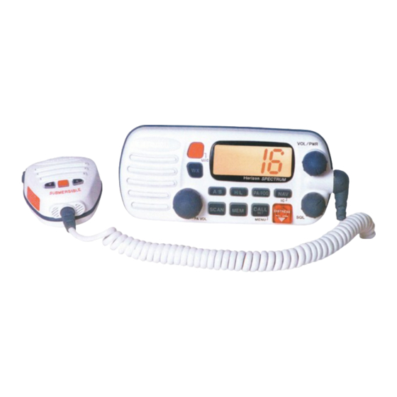
- Page 1 SPECTRUM GX2350S 25 Watt VHF/FM Marine Transceiver Owner ' s Manual Submersible One-Button DSC Distress Call Automatically Sends Latitude & Longitude and Vessel ID Noise Canceling “Clear Voice” Speaker Microphone 20 W Loud Hailer with Bells & Whistles Latitude & Longitude & Speed Over Ground & Course Over Ground Shown On Display When Connected To GPS Programmable Scan &...
-
Page 2: Table Of Contents
TABLE OF CONTENTS FCC NOTICE ......................1 GENERAL INFORMATION ................2 INTRODUCTION ....................2 FCC/ INDUSTRY CANADA INFORMATION ............ 2 ACCESSORIES ....................3 PACKING LIST ....................3 OPTIONS ......................3 CONTROLS AND INDICATORS ..............4 CONTROLS AND CONNECTIONS ..............4 INSTALLATION .................... - Page 3 DIGITAL SELECTIVE CALLING ..............20 GENERAL ...................... 20 Digital Selective Calling (DSC) ..............20 Marine Mobile Service Identity (MMSID) ..........20 SENDING A DISTRESS CALL ............... 21 SENDING A DISTRESS CALL WITH NATURE OF DISTRESS ....22 SENDING AN INDIVIDUAL CALL ..............23 SENDING AN ALL SHIP CALL ..............
-
Page 4: Fcc Notice
Unauthorized changes or modifications to this equipment may void compliance with FCC Rules. Any change or modification must be approved in writing by STANDARD HORIZON, a division of YAESU USA. NOTICE This equipment has been tested and found to comply with the limits for a Class B digital device, pursuant to Part 15 of the FCC Rules. -
Page 5: General Information
GENERAL INFORMATION 1.1 INTRODUCTION The STANDARD HORIZON (a division of YAESEU USA) GX2350S is a VHF/FM transceiver designed for use in the frequency range of 156.025 to 163.275 MHz. The GX2350S requires 13.8V for operation and has a switchable RF output power of 1 watt or 25 watts. -
Page 6: Accessories
ACCESSORIES 2.1 PACKING LIST When the package containing the transceiver is first opened, please check it for the following contents: • GX2350S SPECTRUM Transceiver (White/Black) • CMP351W/CMP351B (White/Black Microphone attached to the transceiver) and hanger kit • Mounting Bracket and attaching hardware •... -
Page 7: Controls And Indicators
CONTROLS AND INDICATORS NOTE This section defines each control of the transceiver. See Figure 1 for location of controls. For detailed operating instructions refer to chapter 4 of this manual. 3.1 CONTROLS AND CONNECTIONS q POWER SWITCH/VOLUME CONTROL Turns the transceiver on and off as well as adjusts the audio volume. To turn the transceiver on press and hold this knob until the LCD turns on. - Page 8 VOL / PWR 16 9 U I C Horizon SPECTRUM PA/FOG CALL SCAN DISTRESS PULL OPEN MENU PA VOL 16/9 Figure 1. Controls and Connectors p a g e 5 Owner’s Manual GX2350S...
- Page 9 WX Key Immediately recalls the previously selected NOAA weather channel from any channel location. Secondary use 1. Holding down the 16/9 key while pressing the WX key changes the mode from USA to International or Canadian. NOTE If position is displayed, this icon will be hidden. 2.
- Page 10 A/B Key Immediately recalls two user assigned channels from any channel. CALL/SET Key The CALL/SET key functions as the enter key. Secondary use Press the CALL/SET key to access the DSC OPERATION menu. The following DSC functions can be accessed from the DSC OPERATION menu;...
-
Page 11: Microphone Speaker
y ACCESSORY CONNECTION CABLE Connects the radio to a GPS, external PA horn, and an external speaker. u DC INPUT CABLE Connects the radio to a DC power supply of 13.8V i ANTENNA JACK Connects an antenna to the transceiver. Use a marine VHF antenna with an impedance of 50 ohms. -
Page 12: Installation
INSTALLATION 4.1 LOCATION 1. The radio can be mounted at any angle. Choose a mounting location that: • is far enough from any compass to avoid any deviation in compass reading due to the speaker magnet • provides accessibility to the front panel controls •... -
Page 13: Accessory Cable
2. Connect the red power wire to a 13.8 VDC 20% power source. Connect the black power wire to a negative ground. 3. If an optional remote extension speaker is to be used, refer to section 4.3 for connections. 4. It is advisable to have a Certified Marine Technician check the power output and the standing wave ratio of the antenna after installation. -
Page 14: Cmb16 Flush Mount Installation
4.4 CMB16 FLUSH MOUNT INSTALLATION 1. Make a rectangular template for the flush mount measuring 2 1/8" H x 5 3/4" W. 2. Use the template to mark the location where the rectangular hole is to be cut. Confirm the space behind the dash or panel is deep enough to accommodate the transceiver (at least 6 inches deep). -
Page 15: Basic Operation
BASIC OPERATION 5.1 RECEPTION 1. After the transceiver has been installed, ensure that the power supply and antenna are properly connected. 2. Press and hold the VOL/PWR knob until the radio turns on. 3. Turn the SQL knob fully counterclockwise. This state is known as “squelch off”. -
Page 16: Transmit Time - Out Timer (Tot)
5.3 TRANSMIT TIME - OUT TIMER (TOT) When the PTT switch on the microphone is held down, transmit time is limited to 5 minutes. This prevents unintentional transmissions. About 10 seconds before automatic transmitter shutdown, a warning beep will be heard from the speaker(s). -
Page 17: Noaa Weather Channels
5.6 NOAA WEATHER CHANNELS 1. To receive a NOAA weather channel, press the WX key from any channel. The transceiver will go to the last selected weather channel. 2. Turn the Channel Selector knob on the microphone to select a different NOAA weather channel. -
Page 18: Memory Scanning
5.8 MEMORY SCANNING NOTE • During scanning, the dot matrix area of the LCD will show MEM- SCAN or PRI-SCAN depending on the scan mode selected. • The channel number shown is the last channel that a transmission was received on. •... -
Page 19: Channel A /B Instant Call
3. The scanning will be performed while receiving MEM HI USA TRIPLE WATCH the MEM CH (memorized channel). 4. To stop scanning, press the SCAN, 16/9, WX, or PTT key. NOTE Triple watch means the radio is watching CH70 for DSC Calls. 5.10 CHANNEL A /B INSTANT CALL Two calling channels (used by an organization or a favorite channel) can be preset. -
Page 20: Operating The Pa Hail Mode
FOG HORN mode: Automatic signaling is transmitted through the PA speaker. 5.11.1. Operating the PA HAIL mode 1. Press the PA/FOG key. PUBLIC ADDRESS Toggle between the PA HAIL and FOG HORN VOLUME mode by pressing the PA/FOG key. 2. Press the PTT switch to speak through the hail speaker. Rotate the Channel Selector knob to control the AF output level. -
Page 21: Navigation Indication
5.12 NAVIGATION INDICATION The transceiver has the ability to display the time and date as well as the vessel’s position (LAT/LON), if connected to a GPS receiver. 1. Press the NAV key to display position JUN15 08:45P 15 KT 160T information. -
Page 22: Resetting The Transceiver's Microprocessor
5.14 RESETTING THE TRANSCEIVER’S MICROPROCESSOR Resetting the microprocessor restores the initial, factory supplied conditions in the transceiver. These are called the default conditions. To reset the microprocessor, first turn the transceiver off. Then while pressing the WX and SCAN keys, turn the transceiver on. The default conditions are: •... -
Page 23: Digital Selective Calling
DIGITAL SELECTIVE CALLING 6.1 GENERAL 6.1.1 Digital Selective Calling (DSC) Digital Selective Calling is a semi-automated method of establishing a radio call, it has been designated by the International Maritime Organization (IMO) as an international standard for establishing VHF, MF and HF radio calls. -
Page 24: Sending A Distress Call
6.2 SENDING A DISTRESS CALL The distress call automatically includes the vessel’s DSC MMSID and Lat/ Lon position. Refer to section 7.7, USER MMSID INPUT. The vessel’s position can be sent only if the transceiver is properly connected to an operating GPS receiver. -
Page 25: Sending A Distress Call With Nature Of Distress
6.3 SENDING A DISTRESS CALL WITH NATURE OF DISTRESS The NATURE OF on type of distress call can be selected and transmitted. The distress call automatically includes the vessels DSC MMSID and Lat/ Lon position. The vessels position will be sent only if the transceiver is properly connected to an operating GPS receiver. -
Page 26: Sending An Individual Call
6.4 SENDING AN INDIVIDUAL CALL This feature allows the user to contact another user using DSC and to automatically switch the receiving DSC radio to a desired working channel. This feature is similar to calling a vessel on CH16 and requesting to go to a weather channel. -
Page 27: Sending An All Ship Call
10. When an individual call acknowledgment with UNATTENED “unable to comply” is received, the established >SEND EXIT channel is automatically selected. 11. To cancel, select EXIT using the Channel Selector knob and press the CALL/SET key. This procedure can be also canceled as follows; Press the CALL/SET key or 16/9 key. -
Page 28: Sc Standby
6.6 DSC STANDBY The DSC Standby function allows the transceiver to reply to DSC calls with the UNATTENDED message and logs the calls in the call waiting directory for return at a more convenient time (This feature is similar to an answer machine). -
Page 29: Peration Of Distress Call Waiting
6.7.1 Operation of Distress Call Waiting 1. Press the CALL/SET key. >INDIVIDUAL ALL SHIP The DSC CALLING menu will appear. STANDBY CALL WAIT 2. Turn the Channel Selector knob to select CALL INDIVIDUAL ALL SHIP WAIT. STANDBY >CALL WAIT 3. Press the CALL/SET key. CALL WAIT >DISTRESS INDIVIDUAL... -
Page 30: Position Request
6. Turn the Channel Selector knob to select the >NAME1 NAME2 name. NAME3 NAME4 JUN15 08:45P 7. Press the CALL/SET key to display the logged ID987654321 >SEND call. EXIT 8. Press the CALL/SET key to resend the INDIVIDUAL CALL. 9. To exit from Individual Call Waiting, select EXIT and press the CALL/SET key. -
Page 31: Receiving Dsc Calls
6. After a DSC position request is transmitted, the transceiver remains on channel 70 until position data is received. 7. The transceiver received position data from a POS REQUEST vessel. 35.88. N 138.20. W 8. If the transceiver does not receive a reply, the NO REPLY LCD will display “>SEND”... -
Page 32: Receiving A Distress Relay Call
6.9.2 Receiving a distress relay call 1. A distress relay call is received. An emergency DISTRESS RLY ID366911111 alarm sounds. 35.88. N 138.20. W Then channel 16 is automatically selected. 2. Press any key to stop the alarm. NOTE You must continue monitoring channel 16 as a coast station may require assistance in any rescue attempt. -
Page 33: Receiving A Position Request
6.9.5 Receiving an individual call When receiving an individual call, an acknowledgment must be sent back to the calling station. 1. An individual call is received. An individual call INDIVIDUAL alarm sounds. Then the radio automatically JUN15 04:00P switches to the requested channel. 2. -
Page 34: Dsc / Radio Setup Mode
DSC / RADIO SETUP MODE 7.1 SETUP 1. Press and hold down the CALL/SET key until >LAMP ADJUST CONTRAST the SETUP menu appears. INDIV DIR POS REPLY 2. To select the items, Turn the Channel Selector knob. NOTE The RAM MIC CMP23 cannot change the SETUP menu. -
Page 35: Individual Directory Setup (Dsc)
3. Turn the Channel Selector knob to select the CONTRAST desired level. (Example: 5 is selected) The contrast is stronger as the selected level increases. 4. Press the CALL/SET key to store the selected level. The LCD will return to the SETUP menu. 7.4 INDIVIDUAL DIRECTORY SETUP (DSC) 1. -
Page 36: Position Request Reply Type
9. Turn the Channel Selector knob to scroll through numbers, 0-9. To enter the desired number and move one space to the right press the CALL/SET key. Repeat procedure until all nine space of MMSID number are entered. 10. After entering the MMSID number press and hold the CALL/SET key until the screen >NEXT EXIT... -
Page 37: Voice Scrambler
7.6 VOICE SCRAMBLER 1. Press and hold the CALL/SET key until the SETUP menu is displayed. 2. Select SCRAMBLER in the SETUP menu with CONTRAST INDIV DIR the Channel Selector knob. POS REPLY >SCRAMBLER 3. Press the CALL/SET key. >CODE CHANNEL The scrambler setup menu will appear. -
Page 38: Key Beep (On Or Off)
7.7 KEY BEEP (ON OR OFF) 1. Press and hold the CALL/SET key until the SETUP menu is displayed. 2. Select KEY BEEP in the SETUP menu with the INDIV DIR POS REPLY Channel Selector knob. SCRAMBLER >KEY BEEP 3. Press the CALL/SET key. >ON The KEY BEEP setting menu will appear. -
Page 39: Time Offset
7.8 TIME OFFSET Sets the time difference between local time and UTC. Time is displayed when position (LAT/LON) is displayed by pressing the NAV key. 1. Press and hold the CALL/SET key until the SETUP menu is displayed. 2. Select TIME SET in the SETUP menu with the POS REPLY SCRAMBLER Channel Selector knob. -
Page 40: User Mmsid Input
7.7 USER MMSID INPUT 1. Press and hold the CALL/SET key until the SETUP menu is displayed. 2. Select the USER MMSID in the SETUP menu SCRAMBLER KEY BEEP with the Channel Selector knob. TIME SET >USER MMSID 3. Press the CALL/SET key. USER MMSID –... -
Page 41: Ram Mic Operation
RAM MIC OPERATION If the optional RAM Mic (CMP23) is connected to the remote microphone connector on the transceiver’s rear panel, then the transceiver can use the remote control operation except for a few functions. The RAM Mic has a maximum range of 50 feet (15 m) with the use of two 10-foot extension cables (CAW23). - Page 42 16/9 SCAN LAMP LAMP CALL CALL Figure 5. CMP23 RAM Mic A/B Key Immediately recalls two user assigned channels from any channel. IC Key Activates the intercom mode between the RAM Mic and the transceiver. Refer to section 8.3, INTERCOM OPERATION. WX Key Immediately recalls a weather channel from any channel location.
-
Page 43: Indicators
DOWN KEY ( Selects the desired channel and adjusts the volume and squelch levels. Each press decreases the channel number, volume level and squelch level. When held down, the channels or levels decrease continuously. UP KEY ( Selects the desired channel and adjusts the volume and squelch levels. Each press increases the channel number, volume level, and squelch level. -
Page 44: Intercom Operation
MEM Indicator The channel is in the transceiver’s scan memory. H/L Indicator “H” is high power. “L” is low power. Blank is a reception only channel. SQL/VOL Indicator “SQL” is squelch adjusting mode. “VOL” is volume adjusting mode. 8.3 INTERCOM OPERATION EXTERNAL SPEAKER NOTE:... -
Page 45: Gx2350S Owner's Manual
MAINTENANCE The inherent quality of the solid-state components used in this transceiver will provide many years of continuous use. Taking the following precautions will prevent damage to the transceiver. * Never key the microphone unless an antenna or suitable dummy load is connected to the transceiver. -
Page 46: Troubleshooting Chart
9.2 TROUBLESHOOTING CHART TROUBLESHOOTING CHART PROBABLE SYMPTOM REMEDY CAUSE No DC voltage to the Press and hold the Power switch/ T r a n s c e i v e r f a i l s t o transceiver, or blown power up. -
Page 47: Specifications
SPECIFICATIONS Performance specifications are nominal, unless otherwise indicated, and are subject to change without notice. 10.1 GENERAL Channels ........... All USA, International and Canadian Input Voltage ..............13.8 VDC Current Drain Standby ..................0.5A Receive ..................1.5A Transmit ..............6A (Hi); 1.7A (Lo) Dimensions .......... - Page 48 page 45 Owner’s Manual GX2350S...
- Page 49 YAESU U. S. A. 17210 Edwards Rd., Cerritos, CA 90703, U.S.A. Printed in Japan 01/00 438B851012...
Need help?
Do you have a question about the SPECTRUM GX2350S and is the answer not in the manual?
Questions and answers