Standard Horizon MATRIX GX2000 Owner's Manual
25 watt vhf/fm marine transceiver
Hide thumbs
Also See for MATRIX GX2000:
- Owner's manual (144 pages) ,
- Owner's manual (116 pages) ,
- Owner's manual (136 pages)
Table of Contents

Related Manuals for Standard Horizon MATRIX GX2000


Summary of Contents for Standard Horizon MATRIX GX2000
- Page 1 MATRIX GX2000/GX2100 25 Watt VHF/FM Marine Transceiver Owner's Manual GX2000S/GX2100S Page 1...
- Page 2 UICK EFERENCE UIDE You can do the basic operation in numerical order of the illustration below. [ PWR/VOL ] K [ CH ] K Press and hold this knob until the LCD Selects the operating channel. turns on, and adjust the audio level. [ 16/9 ] B [ H/L ] B [ SQL ] K...
- Page 3 UICK EFERENCE UIDE [ CH ] K Select the operating [ DISTRESS ] B channel. UTTON ROGRAMMABLE Select the item in Note: for this key to T h e s e t h r e e k e y s the “SETUP MENU”...
-
Page 4: Electrical Connections
UICK NSTALLATION UIDE DESKTOP/OVERHEAD MOUNTING THE RADIO The supplied universal mounting bracket allows desktop or overhead nounting. Use a 13/64” (5.2-mm) bit to drill the holes to a surface which is more 0.4 inch (10 mm) thick and can support more than 3.3 lbs (1.5 kg) and secure the bracket with the supplied screws, spring washers, flat washers, and nuts. -
Page 5: Quick Installation
UICK NSTALLATION UIDE FLUSH MOUNTING THE RADIO The optional MMB-84 Flush-Mount Bracket allows flush mounting the radio to your vessel. 1. To assist in flush mounting, a template has been included. Use this tem- plate to assess the mounting location. 2. -
Page 6: General Information
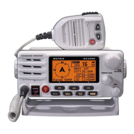
1 GENERAL INFORMATION 1.1 INTRODUCTION The STANDARD HORIZON GX2000/2100 is a VHF/FM Marine Transceiver designed for use in the frequency range of 156.025 to 163.275 MHz. The GX2000/2100 can be operated from 11 to 16 VDC and has a switchable RF output power of 1 watt or 25 watts. -
Page 7: Safety / Warning Information
GX2100 Marine VHF. It should be noted that visiting the Web site from time to time may be beneficial to you, as new products are released they will appear on the STANDARD HORIZON Web site. PRODUCT SUPPORT INQUIRIES If you have any questions or comments regarding the use of the... -
Page 8: Fcc Radio License Information
5 FCC RADIO LICENSE INFORMATION Standard Horizon radios comply with the Federal Communication Commis- sion (FCC) requirements that regulate the Maritime Radio Service. STATION LICENSE An FCC ship station license is no longer required for any vessel traveling in U.S. waters (except Hawaii) which is under 20 meters in length. However, any... -
Page 9: Fcc Notice
Unauthorized changes or modifications to this equipment may void com- pliance with FCC Rules. Any change or modification must be approved in writing by STANDARD HORIZON. NOTICE This equipment has been tested and found to comply with the limits for a Class B digital device, pursuant to Part 15 of the FCC Rules. -
Page 10: Getting Started
7 GETTING STARTED ABOUT VHF RADIO The radio frequencies used in the VHF marine band lie between 156 and 158 MHz with some shore stations available between 161 and 163 MHz. The ma- rine VHF band provides communications over distances that are essentially “line of sight”... -
Page 11: Coaxial Cable
COAXIAL CABLE VHF antennas are connected to the transceiver by means of a coaxial cable – a shielded transmission line. Coaxial cable is specified by it’s diameter and construction. For runs less than 20 feet, RG-58/U, about 1/4 inch in diameter is a good choice. -
Page 12: Installation
8 INSTALLATION LOCATION The radio can be mounted at any angle. Choose a mounting location that: • is far enough from any compass to avoid any deviation in compass read- ing due to the speaker magnet • provides accessibility to the front panel controls •... - Page 13 8.2.2 Optional MMB-84 Flush Mount Bracket 1. Make a rectangular template for the flush mount measuring 2.9” H x 8.1” W (72 x 205 mm). 2. Use the template to mark the location where the rectangular hole is to be cut.
- Page 14 ELECTRICAL CONNECTIONS CAUTION Reverse polarity connections will damage the radio! Connect the power cord and antenna to the radio. Antenna and Power Supply connections are as follows: 1. Mount the antenna at least 3 feet away from the radio. At the rear of the radio, connect the antenna cable.
-
Page 15: Accessory Cable
The NMEA supported sentences are: Input: GLL, GGA, RMC and GNS (RMC sentence is recommended) Output: DSC and DSE (DSC sentences to Standard Horizon Plotter for Position Polling) If you have further inquires, please feel free to contact Product Support at: Phone: (800) 767-2450 Email: marinetech@vxstdusa.com... -
Page 16: Checking Gps Connections
CHECKING GPS CONNECTIONS After connections have been made between the GX2000/GX2100 and the GPS, a small satellite icon will appear on the top right corner of the LCD displayand displays your current location (Latitude/Longitude) on the display. NOTE If there is a problem with the NMEA input from a GPS, the GPS icon will blink continuously until the connection is corrected. -
Page 17: Changing The Time Location
CHANGING THE TIME LOCATION Set the radio show UTC time or local time with the offset inputted in section 8.6 CHANGING THE GPS TIME. 1. Press and hold down the [ CALL ( MENU )] key until “SETUP MENU SETUP MENU” appears, then select “GENERAL SETUP MENU SETUP MENU GENERAL... - Page 18 OPTIONAL CMP30 ENHANCED RAM+ SECOND STATION MIC OR VH-310 HANDSET INSTALLATION The GX2000/GX2100 is capable of using a CMP30 Enhanced RAM+ mic or VH-310 Handset to remotely control the Radio, DSC and PA/Fog functions. In addition the GX2000/GX2100 can operate as a full function intercom system.
- Page 19 Remote Mic or External Speaker Selection By default the RAM+ or VH-310 Handset internal speaker is turned on, how- ever using the RAM+ mic (or VH-310 Handset) this speaker can be turned off so the external speaker can be used. RAM+ mic procedure 1.
-
Page 20: Controls And Indicators
9 CONTROLS AND INDICATORS NOTE This section defines each control of the transceiver. See illustration at the next page for location of controls. For detailed operating instructions refer to chapter 10 of this manual. CONTROLS AND CONNECTIONS CH Knob Rotary knob used to select channels and to choose menu items (such as the DSC menu, Radio Setup and DSC Setup menu). - Page 21 GX2000/GX2100 Page 21...
- Page 22 Programmable Key These three keys functions can be customized by the Setup Menu mode. When press one of these key briefly, the key functions will appear at the LCD bottom. The factory defaults are shown below. [ Left ] Key: [ PA ] function Press this key to activate the 30W PA or FOG Horn Function.
- Page 23 PA Speaker Connection Cable ( Red & Shield ) Connects the GX2000/GX2100 to a optional PA speaker. See section “3 OPTIONS” for a list of optional STANDARD HORIZON Speakers. External Speaker Connection Cable ( White & Shield ) an external speaker. See section “3 OPTIONS” for a list of optional STAN- DARD HORIZON Speakers.
- Page 24 RAM Connector ( Remote Station Microphone Connector ) Connects the GX2000/GX2100 to the CMP30 ( RAM3 ) Remote Station Microphone or the VH-310 Handset. Refer to section “13 CMP30 ( RAM3 ) OPERATION” or “14 VH-310 HANDSET OPERATION” for details PTT Switch ( Push-To-Talk Switch ) Keys the transmitter when the transceiver is in Radio mode.
- Page 25 10 BASIC OPERATION 10.1 PROHIBITED COMMUNICATIONS The FCC prohibits the following communications: • False distress or emergency messages: • Messages to “any boat” except in emergencies and radio tests; • Messages to or from a vessel on land; • Transmission while on land; •...
-
Page 26: Simplex/Duplex Channel Use
10.4 TRANSMIT TIME - OUT TIMER ( TOT ) When the PTT switch on the microphone is held down, transmit time is limited to 5 minutes. This limits unintentional transmissions due to a stuck microphone. About 10 seconds before automatic transmitter shutdown, a warning beep will be heard from the speaker(s). -
Page 27: Emergency ( Channel 16 Use )
1. Program NOAA weather channels into the transceiver’s memory for scan- ning. Follow the same procedure as for regular channels under section “10.13.2 Memory Scanning ( M-SCAN ) .” 2. Press the [ SCAN ] key once to start memory scanning. 3. -
Page 28: Calling Another Vessel ( Channel 16 Or 9 )
8. Give your vessel’s description: length, design (power or sail), color and other distinguishing marks. The total transmission should not exceed 1 minute. 9. End the message by saying “OVER”. Release the microphone button and listen. 10. If there is no answer, repeat the above procedure. If there is still no re- sponse, try another channel. -
Page 29: Making Telephone Calls
10.10 MAKING TELEPHONE CALLS To make a radiotelephone call, use a channel designated for this purpose, The fastest way to learn which channels are used for radiotelephone traffic is to ask at a local marina. Channels available for such traffic are designated Pub- lic Correspondence channels on the channel charts in this manual. - Page 30 10.13 SCANNING Allows the user to select the scan type from Memory scan or Priority scan. “Memory scan” scans the channels that were programmed into memory. “Pri- ority scan” scans the channels programmed in memory with the priority chan- nel. 10.13.1 Selecting the Scan Type 1.
- Page 31 10.13.3 Priority Scanning ( P-SCAN ) In the default setting, Channel 16 is set as the priority channel. You may change the priority channel to the desired channel from the Channel 16 by the Radio Setup Mode, refer to section “12.7 PRIORITY CHANNEL SET.” 1.
-
Page 32: Ais Operation
10.14 AIS OPERATION The GX2000 is equipped with an AIS ( A ) re- UTOMATIC DENTIFICATION YSTEM ceiver and can display the its received data on the display. Therefore, you identify and avoid other large vessels nearby your vessel. The GX2100 also can display the received data on the display if you connect the AIS receiver (not prepared) to the Accessory Connection Cable. -
Page 33: Pa/Fog Operation
The GX2000/GX2100 has a 30W Hailer built-in and can be used with any 4 Ohm PA Horns. Standard Horizon offers a small and a large PA horn called the 220SW and 240SW. When in Hail mode the PA speaker Listen’s Back... - Page 34 10.15.2 Operating the FOG HORN mode Operator can select from “Underway”, “Stop”, “Sail”, “Tow”, “Aground”, “An- chor”, “Horn”, and “Siren”. 1. Press the [ PA ] key, then select “Fog Fog” with the CH knob. 2. Press the CH knob. 3.
- Page 35 TYPE PATTERN USAGE UNDERWAY One 5-second blasts every 120 seconds. Motor vessel underway and making way. Listen Back 120s STOP Two 5-second blasts (separated by 2 Motor vessel underway but seconds) every 120 seconds. stopped (not making way). Listen Back 120s SAIL One 5-second blasts followed by two 1-...
-
Page 36: Intercom Operation
10.16 INTERCOM OPERATION Connecting a CMP30 ( RAM3 ) Remote Station Microphone or VH-310 Hand- set to the GX2000/GX2100 allows intercom communications. Refer to sec- tion “13.2 INTERCOM OPERATION” for CMP30 ( RAM3 ) Remote Station Mi- crophone or section “14.2 INTERCOM OPERATION” for VH-310 Handset. 10.16.1 Communication 1. -
Page 37: Voice Scrambler
10.17 VOICE SCRAMBLER If privacy of communications is desired, a CVS2500 4 code voice scrambler (VS) can be installed in the transceiver. Contact your Dealer to have a CVS2500 installed. Refer to the section “12.17 VOICE SCRAMBLER” to program the voice scrambler. - Page 38 VERTEX STANDARD CO., LTD. Copyright 2009 4-8-8 Nakameguro, Meguro-Ku, Tokyo 153-8644, Japan VERTEX STANDARD CO., LTD. VERTEX STANDARD All rights reserved. US Headquarters 10900 Walker Street, Cypress, CA 90630, U.S.A. No portion of this manual YAESU EUROPE B.V. may be reproduced P.O.
Need help?
Do you have a question about the MATRIX GX2000 and is the answer not in the manual?
Questions and answers