Table of Contents
Advertisement
Quick Links
Integrated 66 Channel GPS antenna
Integrated dual channel AIS (Automatic Identification System) receiver
AIS / AIS SART target display: MMSI, Call Sign, Ship Name, BRG, DST, SOG and COG
4800 or 38400 NMEA baud rate selection, for plotters with 1 NMEA port
True and Magnetic bearing selection on AIS display
Contact Class A or B AIS Ship with DSC
Programmable CPA or TCPA collision avoidance alarms
Meets ITU-R M493-13 Class D DSC (Digital Selective Calling)
Submersible IPX7 (1 m for 30 minutes) front panel
80dB Commercial grade receiver
DSC position request and report functions
30 Watt PA/Loud Hailer with preprogrammed fog signals and listen back
ClearVoice noise canceling speaker microphone with channel selection and 16/9 key
GPS Compass, Waypoint and GPS status pages
Navigation (LAT/LON, Time, SOG and COG) information shown on display
Enter, Save and Navigate to waypoints with Compass page
E2O (Easy-To-Operate) menu system
User customizable soft keys for easy menu operation
Versatile user-programmable scanning, priority scan and Dual Watch
Oversized rotary channel knob with push to enter, backlit display and keys
Local/Distance attenuator
Optional connection for RAM3 second station remote microphone with AIS display
Intercom between radio and RAM3
Voice Scrambler (optional)
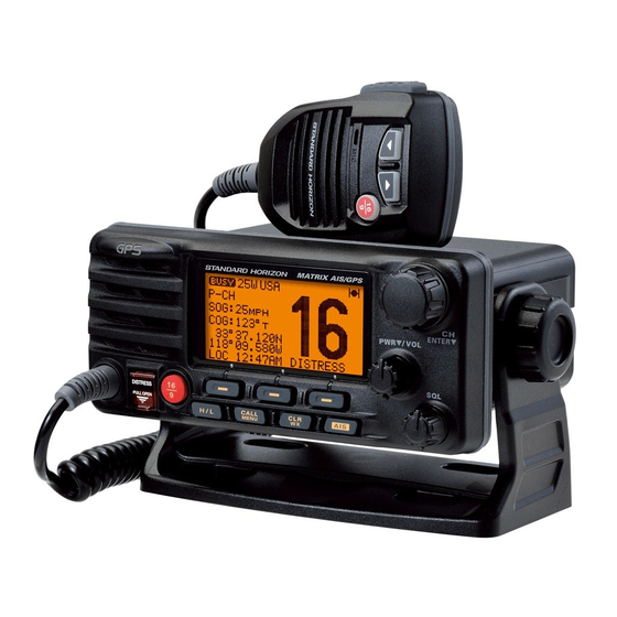
GX2200E
MATRIX AIS/GPS
Marine Transceiver
Owner's Manual
GX2200E
25 Watt VHF/FM
Page 1
Advertisement
Table of Contents

Related Manuals for Standard Horizon MATRIX AIS/GPS GX2200E


Summary of Contents for Standard Horizon MATRIX AIS/GPS GX2200E
- Page 1 MATRIX AIS/GPS GX2200E 25 Watt VHF/FM Marine Transceiver Owner's Manual Integrated 66 Channel GPS antenna Integrated dual channel AIS (Automatic Identification System) receiver AIS / AIS SART target display: MMSI, Call Sign, Ship Name, BRG, DST, SOG and COG 4800 or 38400 NMEA baud rate selection, for plotters with 1 NMEA port True and Magnetic bearing selection on AIS display Contact Class A or B AIS Ship with DSC Programmable CPA or TCPA collision avoidance alarms Meets ITU-R M493-13 Class D DSC (Digital Selective Calling) Submersible IPX7 (1 m for 30 minutes) front panel 80dB Commercial grade receiver DSC position request and report functions 30 Watt PA/Loud Hailer with preprogrammed fog signals and listen back ClearVoice noise canceling speaker microphone with channel selection and 16/9 key GPS Compass, Waypoint and GPS status pages Navigation (LAT/LON, Time, SOG and COG) information shown on display Enter, Save and Navigate to waypoints with Compass page...
-
Page 2: Table Of Contents
TABLE OF CONTENTS Quick Reference Guide ................4 8 DIGITAL SELECTIVE CALLING (DSC) ..........46 8.1 GENERAL ..................46 1 GENERAL INFORMATION ..............5 8.2 MARITIME MOBILE SERVICE IDENTITY (MMSI) ....46 2 PACKING LIST ..................6 8.2.1 What is an MMSI? ............46 3 OPTIONAL ACCESSORIES ..............6 8.2.2 Programming the MMSI ..........47 4 GETTING STARTED................7 4.1 ABOUT VHF RADIO ..............7... - Page 3 TABLE OF CONTENTS 9.6 NMEA DATA IN/OUT ..............91 14 GPS SETUP ..................117 9.7 KEY BEEP .................91 14.1 UNIT POWER ................117 9.8 FOG ALERT TONE FREQUENCY..........92 14.2 COORDINATE SYSTEM............117 9.9 STATION NAME.................93 14.3 PINNING ..................118 9.10 SOFT KEYS ................94 14.4 TIME OFFSET .................118 14.5 TIME AREA ................118 10 CHANNEL FUNCTION SETUP ............96 10.1 CHANNEL GROUP ..............96...
-
Page 4: Quick Reference Guide
uick efeRence uide The GX2200E is equipped with the E2O (Easy-To-Operate) system. Basic operation may be accomplished by following the procedure below: Press and hold the PWR/VOL knob to turn on or off the radio. Rotate the PWR/VOL knob to adjust the speaker audio volume. Rotate the CH knob (or press the microphone’s keys) to select the operating channel. Move the SQL knob clockwise to squelch or counter clockwise to un-squelch the radio. Press the key to toggle the transmit power between High (25W) H / L... -
Page 5: General Information
1 GENERAL INFORMATION The STANDARD HORIZON MATRIX Series GX2200E Marine VHF/FM Marine transceiver is designed to be used in International, USA, and Cana- dian Marine bands. The GX2200E can be operated from 11 to 16 VDC and has a switchable RF output power of 1 watt or 25 watts. The GX2200E integrates a dual channel AIS (Automatic Identification System) receiver to display AIS vessel information (MMSI, Call Sign, Ship Name, BRG, DST, SOG and COG) directly on the VHF radio, so you will know what is out there in any conditions. The GX2200E is also capable of entering and saving up to 100 waypoints, which may be selected and navi- gated to by using a unique navigation compass display. The GX2200E allows... -
Page 6: Packing List
2 PACKING LIST When the package containing the transceiver is first opened, please check it for the following contents: GX2200E Transceiver Power Cord Mounting Bracket and Hardware Flush Mount Template Ferrite Core Owner’s Manual Warranty Card 3 OPTIONAL ACCESSORIES MMB-84 ................Flush-Mount Bracket CMP30B/W ....Remote-Access Microphone (RAM3 Mic, Black/White) CT-100 ............. 7 m Extension Cable for RAM3 Mic CVS2500A ................Voice Scrambler MLS-310 .... 10W amplified External Speaker with on/off Volume control MLS-300 . -
Page 7: Getting Started
4 GETTING STARTED ABOUT VHF RADIO The radio frequencies used in the VHF marine band lie between 156 and 158 MHz with some shore stations available between 161 and 163 MHz. The marine VHF band provides communications over distances that are essen- tially “line of sight” (VHF signals do not travel well through objects such as buildings, hills or trees). Actual transmission range depends much more on antenna type, gain and height than on the power output of the transmitter. -
Page 8: Coaxial Cable
COAXIAL CABLE VHF antennas are connected to the transceiver by means of a coaxial cable – a shielded transmission line. Coaxial cable is specified by it’s diameter and construction. For runs less than 6 m, RG-58/U (about 6 mm in diameter) is a good choice. For runs over 6 m but less than 15 m, the larger RG-8X or RG-213/U should be used for cable runs over 15 m RG-8X should be used. For installation of the connector onto the coaxial cable refer to the figure below. To get your coax cable through a fitting and into your boat’s interior, you may have to cut off the end plug and reattach it later. You can do this if you follow the directions that come with the connector. Be sure to make good soldered connections. EMERGENCY (CHANNEL 16) Channel 16 is known as the Hail and Distress Channel. An emergency may be defined as a threat to life or property. In such instances, be sure the transceiver is on and set to CHANNEL 16. Then use the following proce- dure: 1. Press the microphone push-to-talk switch and say “Mayday, Mayday, ” (your vessel’s name). -
Page 9: Calling Another Vessel (Channel 16 Or 9)
7. Estimate the present seaworthiness and condition of your vessel. 8. Give your vessel’s description: length, design (power or sail), color and other distinguishing marks. The total transmission should not exceed 1 minute. 9. End the message by saying “OVER”. Release the microphone button and listen. 10. If there is no answer, repeat the above procedure. If there is still no response, try another channel. -
Page 10: Bridge Channels 13 And 67
release the PTT button on the mic. Then switch to the new channel. When the new channel is not busy, call the other vessel. After a transmission, say “over,” and release the microphone’s push-to-talk (PTT) switch. When all communication with the other vessel is completed, end the last transmission by stating your Call Sign and the word “out.” Note that it is not necessary to state your Call Sign with each transmission, only at the beginning and end of the contact. Remember to return to Channel 16 when not using another channel. Some radios automatically monitor Channel 16 even when set to other channels or when scanning. BRIDGE CHANNELS 13 AND 67 Channel 13 is used at docks, bridges and by vessels maneuvering in port. Messages on this channel must concern navigation only, such as meeting and passing in restricted waters. -
Page 11: Installation
5 INSTALLATION SAFETY / WARNING INFORMATION IMPORTANT SAFETY INFORMATION Please read this manual carefully to become familiar with the features of this transceiver before using it for the first time. The installation of this equipment should be made in such a manner as to respect the EC recommended electromagnetic field exposure limits (1999/519/EC). -
Page 12: Location
LOCATION The radio can be mounted at any angle. Choose a mounting location that: • is far enough from any compass to avoid any deviation in compass reading due to the speaker magnet • provides accessibility to the front panel controls • allows connection to a power source and an antenna • has nearby space for installation of a microphone hanger • is at least 1 m away from the radio’s antenna • the signal from the GPS satellite can receive sufficiently. Note: To insure the radio does not affect the compass or radios performance is not affected by the antenna location, temporarily connect the radio in the desired location and: a. Examine the compass to see if the radio causes any deviation b. Connect the antenna and key the radio. Check to ensure the radio is operating correctly by requesting a radio check. MOUNTING THE RADIO 5.3.1 Supplied Mounting Bracket The supplied mounting bracket allows overhead or desktop mounting. Use a 5.2 mm bit to drill the holes to a surface which is more 10 mm thick and can support more than 1.5 kg and secure the bracket with the supplied screws, spring washers, flat washers, and nuts. -
Page 13: Optional Mmb-84 Flush Mount Bracket
5.3.2 Optional MMB-84 Flush Mount Bracket 1. Use the supplied template to mark the location where the rectangular hole is to be cut. Confirm the space behind the dash or panel is deep enough to accommodate the transceiver (at least 17 cm deep). There should be at least 1.3 cm between the transceiver’s heatsink and any wiring, cables or structures. 2. Cut out the rectangular hole and insert the transceiver. 3. Fasten the brackets to the sides of the transceiver with the lock washer screw combination; so that the mounting screw base faces the mounting surface (see illustration below). -
Page 14: Electrical Connections
ELECTRICAL CONNECTIONS CAUTION Reverse polarity battery connections will damage the radio! Connect the power cord and antenna to the radio. Antenna and Power Supply connections are as follows: 1. Mount the antenna at least 1 m away from the radio. At the rear of the radio, connect the antenna cable. The antenna cable must have a PL259 connector attached. RG-8/U coaxial cable must be used if the antenna is 7.6 m or more from the radio. RG58 cable can be used for distances less than 7.6 m. -
Page 15: Accessory Cables
Smaller ferrite core Snap together Snap together Bigger ferrite core As close as possible Fuse Replacement To take out the fuse from the fuse holder, hold both ends of the fuse holder and pull the fuse holder apart without bending the fuse holder. When you replace the fuse, please confirm that the fuse is tightly fixed on the metal contact located inside the fuse holder. If the metal contact holding the fuse is loose, the fuse holder may heat up. -
Page 16: Internal Gps (Dsc Output) To Chart Plotter
5.5.1 Internal GPS (DSC Output) to Chart Plotter 4800 Baud Connections PA Speaker Shield GPS Chart Plotter Radio Wires Plotter Connection Blue: NMEA IN ( ) No Connection Green: NMEA IN ( ) No Connection Gray: NMEA OUT ( ) NMEA IN ( ) Brown: NMEA OUT ( ) NMEA IN ( ) - Page 17 38400 Baud Connections PA Speaker Shield GPS Chart Plotter Radio Wires Plotter Connection Blue: NMEA IN ( ) No Connection Green: NMEA IN ( ) No Connection Gray: NMEA OUT ( ) NMEA IN ( ) Brown: NMEA OUT ( ) NMEA IN ( ) Yellow: NMEA-HS OUT ( ) No Connection...
-
Page 18: Connection To External Gps Or Chart Plotter
5.5.2 Connection to External GPS or Chart Plotter 4800 Baud Connections PA Speaker Shield GPS Receiver Radio Wires Plotter Connection Blue: NMEA IN ( ) NMEA OUT ( ) Green: NMEA IN ( ) NMEA OUT ( ) Gray: NMEA OUT ( ) NMEA IN ( ) Brown: NMEA OUT ( ) NMEA IN ( ) - Page 19 38400 Baud Connections PA Speaker Shield GPS Receiver Radio Wires Plotter Connection Blue: NMEA IN ( ) NMEA OUT ( ) Green: NMEA IN ( ) NMEA OUT ( ) Gray: NMEA OUT ( ) NMEA IN ( ) Brown: NMEA OUT ( ) NMEA IN ( ) Yellow: NMEA-HS OUT ( ) No Connection...
- Page 20 External GPS Connections (4800 baud or 38400 baud) The GX2200E can select the NMEA baud rate between “4800 bps” and “38400 bps”. Refer to section “9.6 NMEA DATA IN/OUT” for selection. NMEA Input (GPS Information) • GX2200E can read NMEA-0183 version 2.0 or higher. • The NMEA 0183 input sentences are GLL, GGA, RMC, GNS, GSA, and GSV (RMC sentence is recommended). • If 4800 baud (default) is selected: a. If there is a selection for “PARITY” select “NONE”. b. The Blue and Green wires of input are at 4800 baud. • If 38400 baud is selected: The Blue and Green wires of input are at 38400 baud. NMEA Output (DSC and GPS information) • The NMEA 0183 output sentences are DSC and DSE. • If 4800 baud (default) is selected: a. The Gray and Brown wires output DSC and DSE sentences. b. The Yellow and White wires of output AIS VDM sentence at 38400 baud.
-
Page 21: Checking Gps Connections
CHECKING GPS CONNECTIONS When the GX2200E receives the GPS signal through the internal GPS, or from an external GPS antenna or 25.0 chart plotter, a small satellite icon or “ IO ” will appear 50 37.660 000 55.989 on the top right corner of the display and your current 12:56 location (latitude/longitude) is shown on the display. NOTE If there is a problem with the NMEA connection between the radio and the GPS, the GPS icon will blink continuously until the connec- tion is corrected. -
Page 22: Changing The Gps Time
CHANGING THE GPS TIME From the factory the GX2200E shows GPS satellite time or UTC (Universal Time Coordinated) time. A time offset is needed to show the local time in your area. The time offset must be changed in order for the radio to display the current time in your area. See the Offset Time Table below. ffSet abLe 1. Press and hold the key until “ Setup CALL MENU Menu ” appears, then select “ GPS SETUP ” with the CH knob. 2. Press the soft key, then select “ TIME OFFSET ” with the CH knob. 3. Press the soft key, then rotate the -Time Offset-... -
Page 23: Changing The Time Location
CHANGING THE TIME LOCATION This menu selection allows the radio to show UTC time or local time with the offset. 1. Press and hold the key until “ Setup Menu ” CALL MENU appears, then select “ GPS SETUP ” with the CH knob. 2. Press the soft key, then rotate the CH knob to “ TIME AREA ”. 3. Press the soft key. -
Page 24: Changing Cog To True Or Magnetic
5.10 CHANGING COG TO TRUE OR MAGNETIC Allows the GPS COG (Course Over Ground) and the BRG from an AIS target to be selected to show in True or Magnetic. Factory default is “True” however by following the steps below the COG can be changed to “Magnetic”. 1. Press and hold the key until “ Setup Menu ” CALL MENU appears, then select “ GPS SETUP ” with the CH knob. 2. Press the soft key, then rotate the CH knob to select “ MAGNETIC ”. 3. Press the soft key. -
Page 25: Optional Cmp30 ( Ram3 ) Installation
5.11 OPTIONAL CMP30 ( RAM3 ) INSTALLATION The GX2200E is capable of using a CMP30 ( RAM3 ) Remote Station Micro- phone to remotely control the Radio, AIS, DSC and PA/Fog functions. In addition the GX2200E can operate as a full function intercom system between the CMP30 ( RAM3 ) and the GX2200E. WARNING Do not connect or remove the CMP30 (RAM3) microphone while the radio is powered on. - Page 26 External Speaker Connections Ferrite Core Gasket Wall Routing Cable Mounting Bracket NOTE Caution!: Before cutting the cable, it must be disconnected from the rear panel of the transceiver. The routing cable can be cut and spliced, however care needs to be taken when reconnecting the wires to ensure water integrity. After cutting you will notice there are the following wires: Yellow, White, Brown, Gray, Blue, Green, Red/White , Shield The red/white and shield wires are wrapped in foil. Remove the foil, and separate the red/white and shield wires. WARNING It is not recommended to plug or unplug the CMP30 ( RAM3 ) Remote Station Microphone into the routing cable while the radio is on. Page 26 GX2200E...
-
Page 27: Connecting An External Speaker To The Ram3 Mic Cable
5.11.1 Connecting an External Speaker to the RAM3 Mic Cable In noisy locations and optional external speaker may be connected to the white speaker wires on the RAM3 routing cable. The RAM3 can drive the internal speaker or the external speaker one at a time. When connecting an external speaker, follow the procedure below to turn off the RAM3 audio and enable the external speaker wires on the RAM3 routing cable. 1. On the RAM3 mic, press and hold the key until “... -
Page 28: Controls And Indicators
6 CONTROLS AND INDICATORS NOTE This section defines each control of the transceiver. See illustra- tion at the next page for location of controls. For detailed operating instructions refer to chapter 8 of this manual. FRONT PANEL CH Knob (Channel Selection) Rotary knob is used to select channels and to choose menu items (such as the DSC menu, General Setup and DSC Setup menu). The keys on the microphone can also be used to select channels and menu items. Secondary use Press this knob to enter a selection in the setup menu or DSC menu. While holding the soft key and turning this knob, you can confirm memory channels that have been programmed for scanning. -
Page 29: Channels
Secondary use When in PA or Fog mode, controls the listen-back volume. SQL Knob ( Squelch Control ) Adjusting this control clockwise, sets the point at which random noise on the channel does not activate the audio circuits but a received signal does. This point is called the squelch threshold. Further adjustment of the squelch control will degrade reception of wanted transmissions. Soft Keys The 3 programmable soft keys can be customized by the Setup Menu mode described in section “9.10 SOFT KEYS”. When one of the soft keys is pressed briefly, the functions will appear above each key on the display. -
Page 30: Rear Panel
Key DISTRESS Used to send a DSC distress call. To send the distress call refer to section “8.3.1 Transmitting a DSC Distress Call”. REAR PANEL Never remove this rubber cap. When this rubber cap is removed, the water resistance performance is lost. -
Page 31: Microphone
D C Input Cable Connects the radio to a DC power supply capable of delivering 11 to 16V A ccessory Connection Cable ( Blue, Green, Gray, Brown, Yellow & White ) Connects the GX2200E to a GPS chart plotter. Refer to section “5.5 ACCESSORY CABLES”. RAM3 Connector ( Remote Station Microphone Connector ) Connects the GX2200E to the CMP30 ( RAM3 ) Remote Station Micro- phone. Refer to section “16 CMP30 ( RAM3 ) REMOTE MIC OPERA- TION” for details. - Page 32 Microphone Speaker Audio heard through internal radio speaker is heard through speaker inside the microphone. Keys (DOWN/UP Keys) keys on the microphone are used to select channels and to choose menu items (such as the DSC menu, General Setup and DSC Setup menus). Key Pressing the key immediately recalls Channel 16 from any location. Press and hold the key to recall Channel 9. Pressing the key again will revert the radio to the previous selected channel. Page 32 GX2200E...
-
Page 33: Basic Operation
7 BASIC OPERATION RECEPTION 1. After the transceiver has been installed, ensure that the power supply and antenna are properly connected. 2. Press and hold the PWR/VOL knob until the radio turns on. 3. Rotate the SQL knob fully counterclockwise. This state is known as “squelch off”. 4. Turn up the PWR/VOL knob until noise or audio from the speaker is at a comfortable level. 5. Rotate the SQL knob clockwise until the random noise disappears. This state is known as the “squelch threshold.” 6. Rotate the CH knob to select the desired channel. Refer to the channel chart on Page 130 for available channels. -
Page 34: Simplex/Duplex Channel Use
SIMPLEX/DUPLEX CHANNEL USE Refer to the VHF MARINE CHANNEL CHART (Page 130) for instructions on use of simplex and duplex channels. NOTE All channels are factory-programmed in accordance with FCC (USA), Industry Canada (Canada), and International regulations. Mode of operation cannot be altered from simplex to duplex or vice-versa. DISPLAY TYPE The GX2200E display can be setup to show displays other than the default “NORMAL” VHF display by using the procedure below: 1. Press and hold the key until “ Setup Menu ” CALL MENU appears, then select “ GENERAL SETUP ” with the CH knob. 2. Press the soft key, then rotate the CH knob to select “... -
Page 35: International, Usa, And Canada Mode
NOTE When the “ GPS STATUS ” mode is selected in step 4 above, the display will show the GPS status until a key is pressed. INTERNATIONAL, USA, AND CANADA MODE To change the channel group from International to USA or Canada: 1. Press and hold the key until “ Setup CALL MENU Menu ” appears. 2. Rotate the CH knob to select “ CH FUNCTION SETUP ”. 3. Press the soft key, then rotate the CH knob to select “... -
Page 36: Scanning
NOTE The priority channel may be changed from CH16 to another channel. Refer to section “10.5 PRIORITY CHANNEL”. SCANNING The GX2200E will automatically scan channels programmed into the preset channel memory and the scan channel memory. When an incoming signal is detected on one of the channels during scan, the radio will pause on that channel, allowing you to listen to the incoming trans- mission. The radio will automatically start scanning again after the transmis- sion stops. 7.8.1 Selecting the Scan Type 1. Press and hold the key until “ Setup CALL MENU Menu ” appears. 2. Rotate the CH knob to select “ CH FUNCTION SETUP ”. 3. Press the soft key, then select “ SCAN TYPE ” with the CH knob. 4. Press the soft key. -
Page 37: Programming Scan Memory
7.8.2 Programming Scan Memory 1. Press and hold the key until “ Setup Menu ” CALL MENU appears. 2. Rotate the CH knob to select “ CH FUNCTION SETUP ”. 3. Press the soft key, then rotate the CH knob to select “ SCAN MEMORY CH ”. 4. Press the soft key. -
Page 38: Priority Scanning (P-Scan)
7.8.4 Priority Scanning (P-SCAN) In the default setting, Channel 16 is set as the priority channel. You may change the priority channel to the desired channel from Channel 16 by the General Setup mode, refer to section “10.5 PRIORITY CHANNEL”. 1. Adjust the SQL knob until background noise disappears. 2. Press one of the soft key, then press the soft key. “ P-SCAN ” appears on the display. Scan- 25.0 ning will proceed between the memorized chan- 50 37.660... -
Page 39: Operation
7.9.2 Operation 1. Press one of soft keys, then press the soft PRESET key to recall the preset channel. The “P SET” icon 25.0 will appear on the display. 50 37.660 000 55.989 2. Rotate the CH knob to select the desired preset 12:56 channel (“0” ~ “9”). The preset channel number 25.0 appears (“ P-SET0 ” - “ P-SET9 ”) while selecting the 50 37.660 preset channel. -
Page 40: Pa/Fog Operation
7.10 PA/FOG OPERATION The GX2200E has a 30W hailer built-in and can be used with any 4 Ohm PA horn. Standard Horizon offers two HAIL/PA horns, the 220SW (12 cm round 30 Watt HAIL/PA horn) and the 240SW (13 x 20 cm rectangular 40 Watt HAIL/PA horn). When the GX2200E is in PA Hail mode the PA speaker listens back (acts as a microphone and provides two-way communications through the PA horn to the main radio). -
Page 41: Operating The Fog Horn Mode
NOTE When in the PA HAIL mode it is possible to simultaneously use the AIS page by pressing the key. 7.10.2 Operating the FOG HORN mode The user can select the type of horn from “Underway”, “Stop”, “Sail”, “Tow”, “Aground”, “Anchor”, “Horn”, and “Siren”. 1. Press one of the soft keys, then press the PA/FOG soft key. Note: The soft key may have to be pressed to see the soft key if the soft keys PA/FOG have not be customized. 2. Rotate the CH knob to select “ FOG ”, then press soft key. -
Page 42: Fog Signal Timing Chart
7.10.3 Fog Signal Timing Chart TYPE PATTERN USAGE UNDERWAY One 5-second blasts every 120 seconds. Motor vessel underway and making way. Listen Back 120s STOP Two 5-second blasts (separated by 2 seconds) Motor vessel underway but every 120 seconds. stopped (not making way). Listen Back 120s SAIL One 5-second blasts followed by two 1-second S a i l i n g v e s s e l u n d e r w a y, blasts (separated by 2 seconds) every 120 fishing vessel (underway or seconds. -
Page 43: Intercom Operation
7.11 INTERCOM OPERATION An optional RAM3 (CMP30) must be connected to perform intercom func- tions between the radio and the RAM3 (CMP30). In addition, to access the following intercom functions one of the soft keys must be setup as . Refer to section “9.10 SOFT KEYS”. 7.11.1 Communication 1. Press one of the soft keys, then press the soft key to enable the intercom mode. Note: Depending on the programming of the 50 37.660 000 55.989 soft key, the... -
Page 44: Voice Scrambler
7.12 VOICE SCRAMBLER If privacy of communications is desired, a CVS2500A 4-code voice scram- bler (VS) can be installed in the transceiver. Contact your Dealer to have a CVS2500A installed. Refer to the section “10.7 SCRAMBLER SETUP” to program the voice scrambler. 1. Select a channel that was programmed for scrambler mode (“ Vs ” and scrambler number will 25.0 appear on the display). 50 37.660 000 55.989 2. Monitor the channel before transmitting. -
Page 45: Demo Mode
7.13 DEMO MODE This mode is used by Standard Horizon sales persons and dealers to demonstrate radio, DSC and AIS functions. Demo mode allows latitude, longitude and time to be entered to simulate radio displays. When the demo mode is enabled, the radio display will automatically switch from the NORMAL, COMPASS, AIS and WAYPOINT displays. -
Page 46: Digital Selective Calling (Dsc)
8 DIGITAL SELECTIVE CALLING (DSC) GENERAL WARNING This GX2200E is designed to generate a digital maritime distress and safety call to facilitate search and rescue. To be effective as a safety device, this equipment must be used only within communica- tion range of a shore-based VHF marine channel 70 distress and safety watch system. The range of signal may vary but under normal conditions should be approximately 20 nautical miles. -
Page 47: Programming The Mmsi
8.2.2 Programming the MMSI WARNING The MMSI can be inputted only once. Therefore please be care- ful not to input the incorrect MMSI number. If you need to change the MMSI number after it has been entered, the radio will have to be returned to Factory Service. Refer to the section “17.2 FACTORY SERVICE.” 1. Press and hold the key until “ Setup CALL MENU Menu ” appears. -
Page 48: Dsc Distress Call
DSC DISTRESS CALL The GX2200E is capable of transmitting and receiving DSC distress messag- es to all DSC radios. The GX2200E may be connected to a GPS to also transmit the latitude and longitude of the vessel. 8.3.1 Transmitting a DSC Distress Call NOTE To be able to transmit a DSC distress call an MMSI number must be programmed, refer to section “8.2.2 Programming the MMSI.” In order for your ships location to be transmitted, the internal GPS must be able to receive a fix or a optional GPS antenna or chart plotter must be connected. Refer to section “5.5 ACCESSORY CABLES.”... - Page 49 Transmitting a DSC Distress Alert with Nature of Distress The GX2200E is capable of transmitting a DSC distress alert with the follow- ing “Nature of Distress” categories: Undesignated, Fire, Flooding, Collision, Grounding, Capsizing, Sinking, Adrift, Abandoning, Piracy, MOB 1. Press the key. The “ D S C M e n u ” will CALL MENU appear. 2. Rotate the CH knob to select “ DISTRESS ALERT MSG ”.
- Page 50 Transmitting a DSC Distress Alert with Manual Position of Input When the GX2200E is not connected to a GPS receiver, you may input the latitude and longitude of your vessel manually before you send a DSC distress alert. 1. Press the key. The “...
-
Page 51: Receiving A Dsc Distress Call
Canceling a DSC Distress Call If a DSC distress call was sent by error the GX2200E allows you to send a message to other vessels to cancel the distress call that was made. Press the soft key, then press the soft key. 50 37.660 000 55.989 10:00 02:25 8.3.2 Receiving a DSC Distress Call 1. When a DSC distress call is received, an emer- 123456789 gency alarm sounds. - Page 52 5. When you finish entering the waypoint name, press and hold the soft key to replace the 50 35.846 display to the waypoint screen. The display indi- 001 01.623 cates the distance and direction of the distressed vessel, and also the compass indicates the distressed vessel by dot ( ) . 12.3 50 37.660 6. To stop navigating to a waypoint, press one of the 000 55.989 12:56 soft keys, then press the soft key. The...
-
Page 53: All Ships Call
ALL SHIPS CALL The all ships call function allows contact to be established with DSC equipped vessels without having their MMSI in the individual calling direc- tory. Also, priority for the call can be designated as “Urgency” or “Safety”. URGENCY Call: This type of call is used when a vessel may not truly be in distress, but have a potential problem that may lead to a distress situation. This call is the same as saying “PAN PAN, PAN PAN, PAN PAN” on Channel 16. -
Page 54: Receiving An All Ships Call
8.4.2 Receiving an All Ships Call 1. When an all ships call is received, an emergency alarm will sound. The display shows the MMSI of the vessel trans- 01:03 mitting the all ships call and the radio will change to the requested channel after 10 seconds. 123456789 2. Press any key to stop the alarm. 3. Monitor the requested channel until the all ships 01:03 voice communication is completed. On the display you will notice 3 soft key selec- 25.0 tions. These selections are described below: 50 37.660 : Press this key to accept the DSC all 000 55.989 12:56... -
Page 55: Individual Call
INDIVIDUAL CALL This feature allows the GX2200E to contact another vessel with a DSC VHF radio and automatically switch the receiving radio to a desired communica- tions channel. This feature is similar to calling a vessel on CH16 and request- ing to go to another channel (switching to the channel is private between the two stations). Up to 80 individual contacts may be programmed. 8.5.1 Setting up the Individual / Position Call Directory The GX2200E has a DSC directory that allows you to store a vessel or person’s name and the MMSI (Maritime Mobile Service Identity Number) number associated with vessels you wish to transmit individual calls, auto polling, position request, position report, and polling transmissions. -
Page 56: Setting Up The Individual Call Reply
If a mistake was made entering in the name repeat pressing the soft key until the wrong character is selected, then rotate the CH knob to correct the entry. 9. After the eleventh letter or space has been entered, press and hold the soft key to advance to the MMSI number entry. 10. Rotate the CH knob to scroll through -Individual Directory- numbers, 0-9. To enter the desired number Individual Name Horizon and move one space to the right by pressing ID:123456789 soft key. Repeat this procedure BACK QUIT until all nine space of the MMSI number are entered. If a mistake was made entering in the MMSI number repeat pressing the soft key until the wrong number is selected, then rotate the CH knob to correct the entry. 11. To store the data entered, press and hold the soft key. -
Page 57: Enabling The Individual Call Acknowledgment
8.5.3 Enabling the Individual Call Acknowledgment The radio can select either reply message “Able” (default) or “Unable” when the individual reply setting (described in the previous section) is set to “AUTOMATIC”. 1. Press and hold the key until “ Setup CALL MENU Menu ” appears. 2. Rotate the CH knob to select “ DSC SETUP ” menu. 3. Press the soft key, then select -DSC Setup- “... - Page 58 6. Press the soft key, then rotate the CH knob to select the operating channel you want to communicate on, then press soft key. 7. Press the soft key to transmit the individual DSC signal. 8. When an individual call acknowledgment is received, the established channel is auto- matically changed to the channel which is selected on step 6 above and a ringing tone sounds.
-
Page 59: Receiving An Individual Call
9. Rotate the CH knob to select the nature of call (“ ROUTINE ”, “ SAFETY ”, or “ URGENCY ”), then press the soft key. 10. Rotate the CH knob to select the operating channel you want to communicate on, then press the soft key. 11. Press the soft key to transmit the -Individual Call- individual DSC signal. Name: ID:345678901 12. W hen an individual call acknowledgment is Category:Routine CH: 08 received, the established channel is auto- Transmit? QUIT... - Page 60 Manual reply: 1. When an individual call is received, an individual call ringing alarm sounds. The display shows the MMSI of the vessel trans- mitting the individual call and the radio will change to the requested channel after 10 seconds. 2. Press any key to stop the alarm. 3. Monitor the requested channel until the message is completed. On the display you will notice 3 soft key selec- 25.0 tions. These selections are described below: 50 37.660 : Press this key to accept the DSC individ- 000 55.989 12:56 ual call and to switch to requested channel. Note: If a key is not pressed for 30 seconds or longer the radio will auto- matically change to the requested channel. : Press this key to temporarily disable automatic switching to the requested channel. Note: In some cases automatically switching to a requested chan- nel might disrupt import ongoing communications. This feature allows commercial users to suspend channel switching and stay on the working channel selected before the all ships call was received.
-
Page 61: Setting Up The Individual Call Ringer
8.5.6 Setting up the Individual Call Ringer When an individual call is received the radio will produce a ringing sound for 2 minutes. This selection allows the individual call ringer time to be changed. 1. Press and hold the key until “ Setup CALL MENU Menu ” appears. 2. Rotate the CH knob to select “ DSC SETUP ” menu. 3. Press the soft key, then select -DSC Setup- “ INDIVIDUAL RING ” with the CH knob. Individual Directory Individual Reply Individual Ack 4. Press the... -
Page 62: Group Call
GROUP CALL This feature allows the user to contact a group of specific vessels (e.g. members of a yacht club) using DSC radios with group call function to auto- matically switch to a desired channel for voice communications. This func- tion is very useful for yacht clubs and vessels traveling together that want to collectively make announcements on a predetermined channel. Up to 32 group MMSIs may be programmed. - Page 63 1. Press and hold the key until “ Setup CALL MENU Menu ” appears. 2. Rotate the CH knob to select “ DSC SETUP ” menu. 3. Press the soft key, then select -DSC Setup- “ GROUP DIRECTORY ” with the CH knob. Individual Directory Individual Reply 4. Press the soft key, then select “ ADD ” Individual Ack Individual Ring with the CH knob.
-
Page 64: Transmitting A Group Call
8.6.2 Transmitting a Group Call Group Call using the Group Directory 1. Press the key. The “ DSC Menu ” will CALL MENU appear. 2. Rotate the CH knob to select “ GROUP ”. (To cancel, press the soft key.) 3. Press the soft key. The transceiver will beep, and the last group calls will appear. - Page 65 Group Call by Manually Entering an MMSI This feature allows you to contact a group of vessels by entering in their group MMSI manually. 1. Press the key. The “ DSC Menu ” will CALL MENU appear. 2. Rotate the CH knob to select “ GROUP ”. (To cancel, press the soft key.) 3. Press the...
-
Page 66: Receiving A Group Call
8.6.3 Receiving a Group Call 1. When a group call is received, the GX2200E will produce a ringing alarm sound. 2. The display shows the group MMSI number. 3. Press any key to stop the alarm. 4. Monitor the channel for the person calling the group for a message. On the display you will notice 3 soft key selections. These selections are described below: : Press this key to accept the group call and to switch to request- ed channel. Note: If a key is not pressed for 30 seconds or longer the radio will auto- matically change to the requested channel. : Press this key to temporarily disable automatic switching to the requested channel. : Press this key to quit the automatic channel switching and revert to the last selected working channel. 5. If you want to respond, monitor the channel to make sure it is clear, then press the microphone’s PTT switch and talk into the microphone to the group of vessels. -
Page 67: Setting Up The Group Call Ringer
8.6.4 Setting up the Group Call Ringer The GX2200E has the capability to turn off the group call ringer. 1. Press and hold the key until “ Setup CALL MENU Menu ” appears. 2. Rotate the CH knob to select “ DSC SETUP ” menu. 3. Press the soft key, then select “ DSC BEEP ” with the CH knob. 4. Press the soft key. 5. Rotate the CH knob to select “ Group ”, then press the soft key. -
Page 68: Position Request
POSITION REQUEST Advancements in DSC have made it possible to poll the location of another vessel and show the position of that vessel on the display of the GX2200E. Standard Horizon has taken this feature one step further, if any compat- ible GPS chart plotter is connected to the GX2200E, the polled position of the vessel is shown on the display of the GPS chart plotter making it easy to navigate to the location of the polled vessel. This is a great feature for anyone wanting to know the position of another vessel. For example your buddy that is catching fish, or finding the location of a person you are cruis-... -
Page 69: Transmitting A Position Request To Another Vessel
5. Press the soft key to store the selected setting. 6. Press the soft key two times to return to radio operation. 8.7.2 Transmitting a Position Request to Another Vessel Position Request using the Individual/Position Directory 1. Press the key. The “ DSC Menu ” will CALL MENU appear. 2. R o t a t e t h e C H k n o b t o s e l e c t “ P O S REQUEST ”, then press the soft key. -
Page 70: Receiving A Position Request
4. Rotate the CH knob to select “ MANUAL ,” then press the soft key. 5. Rotate the CH knob to select the first number of the MMSI (nine digits) which you want to contact, then press the soft -POS Request Call- key to step to the next number. Input MMSI 6. Repeat step 5 to set the MMSI number. ID:--------- If a mistake was made entering in the MMSI -POS Request Call- SELECT BACK QUIT number, repeatedly press the soft Input MMSI ID:345678901 key until the wrong number is selected, then... -
Page 71: Setting Up A Position Request Ringer
Manual reply: 1. When a position request call is received from Received POS Request Name:Horizon another vessel, the display will be as shown in ID:123456789 Category:Routine the illustration at the right. Since: 01:03 2. A ringing alarm sounds 4 times. To send your REPLY QUIT vessels position to the requesting vessel, press Received POS Request... -
Page 72: Position Report
POSITION REPORT The feature is similar to position request, however instead of requesting a position of another vessel this function allows you to send your position to another vessel. Your vessel must mark the internal GPS receiver for the GX2200E to send the position. NOTE To transmit a position report call, the GX2200E individual directory must be programmed with stations you wish to send your position... - Page 73 DSC Position Report Call Manually Entering an MMSI This feature allows you to send your position to another vessel by manually entering the MMSI of the ship you want to send your position to. 1. Press the key. The “ DSC Menu ” will CALL MENU appear. 2. Rotate the CH knob to select “ POS REPORT ”. (To cancel, press the soft key.) 3. Press the soft key. The transceiver will beep, and the POS report call menu will -POS Report Call- appear. Input MMSI ID:--------- 4. Rotate the CH knob to select “...
-
Page 74: Receiving A Dsc Position Report Call
8.8.2 Receiving a DSC Position Report Call When another vessel transmits their vessels location to the GX2200E the following will happen: 1. A ringing sound will be produced when the call is received and NMEA sentences (DSC, DSE) are 123456789 outputted so the position can be shown on a chart 01:03 plotter or a computer. 2. Press any key to stop ringing. 3. Rotate the CH knob to see position information of the station. 4. To exit to radio mode, press the soft key. 8.8.3 Navigating to a Position Report The GX2200E has a feature that allows navigation to a received position report call by using the compass display. Navigating to the position of a posi-... -
Page 75: Saving A Position Report As A Waypoint
8.8.5 Saving a Position Report as a Waypoint The GX2200E can save a position report call in the radio’s memory as a waypoint. 1. After the position report call has been 123456789 received, press the soft key. 2. Rotate the CH knob to change the first 01:03 letter in the name of the waypoint and press soft key. -
Page 76: Setting Up A Position Report Ringer
8.8.7 Setting up a Position Report Ringer The GX2200E has the capability to turn off the position report ringer. 1. Press and hold the key until “ Setup CALL MENU Menu ” appears. 2. Rotate the CH knob to select “ DSC SETUP ” menu. 3. Press the soft key, then select “ DSC BEEP ” with the CH knob. 4. Press the soft key, then select “ POS Report ” with the CH knob. 5. Press the soft key, then select “... -
Page 77: Manual Input Of A Gps Location (Lat/Lon)
MANUAL INPUT OF A GPS LOCATION (LAT/LON) You may send the latitude and longitude of your vessel manually even if the GX2200E is located in an area where GPS reception is limited. After the position is entered, transmitting a DSC distress, position request, or position report will contain the manually entered position. 1. Press and hold the key until “ Setup CALL MENU Menu ” appears. 2. Rotate the CH knob to select “ GPS SETUP ” menu. 3. Press the soft key, then select “ POSITION INPUT ” with the CH knob. 4. Press the soft key. The transceiver will beep, and the display will be as shown in the illustration on the right. -
Page 78: Auto Pos Polling
8.10 AUTO POS POLLING The GX2200E has the capability to automatically track four stations programmed into the individual directory. The following procedure allows the time interval between position requests to be setup. 8.10.1 Setting up the Polling Time Interval 1. Press and hold the key until “ Setup CALL MENU Menu ” appears. 2. Rotate the CH knob to select “... -
Page 79: Enabling/Disabling Auto Pos Polling
5. T h e r a d i o w i l l s h o w t h e s t a t i o n s programmed in the individual directory. Rotate the CH knob to select the desired -Auto POS Polling- CALL 1:HORIZON station and press the... -
Page 80: Dsc Test
8.11 DSC TEST This function is used to contact another DSC equipped vessel to ensure the DSC functions of the radio are operating. NOTE To use this feature, the radio you will be transmitting the test call to needs to have the DSC Test feature. To perform the DSC test you will need to enter a MMSI of another vessel into the individual directory or manually enter in the MMSI using the procedure below. 8.11.1 Programming MMSI into Individual Directory Refer to section “8.5.1 Setting up the Individual / Position Call Directory”. 8.11.2 DSC Test call by using Individual/Position Directory 1. Press the key. The “... -
Page 81: Dsc Test Call By Manually Entering An Mmsi
8.11.3 DSC Test Call by Manually Entering an MMSI 1. Press the key. The “ DSC Menu ” will CALL MENU appear. 2. Rotate the CH knob to select “ DSC TEST ”, then press the soft key. 3. Rotate the CH knob to select “ MANUAL ” and press the soft key. 4. Rotate the CH knob to select the first digit in the MMSI and press the soft key. -
Page 82: Polling Call
8.12 POLLING CALL The GX2200E has the capability to track another vessel. 8.12.1 Transmitting a Polling Call to Another Vessel Polling Call using the Individual/Position Call Directory 1. Press the key. The “ DSC Menu ” will CALL MENU appear. 2. Rotate the CH knob to select “ POLLING ”, then press the soft key. -
Page 83: Receiving A Polling Call
Polling Call by Manually Entering an MMSI This feature allows you to contact a vessel by manually entering the MMSI of the ship you want to track. 1. Press the key. The “ DSC Menu ” will CALL MENU appear. 2. Rotate the CH knob to select “ POLLING ”, then press the soft key. 3. Rotate the CH knob to select “ MANUAL ” and press the soft key. -
Page 84: Dsc Log Operation
8.13 DSC LOG OPERATION The GX2200E logs transmitted calls, received DSC distress calls, and other calls (individual, group, all ships, etc.). The DSC log feature is similar to an answer machine where calls are recorded for review and a “ ” icon will appear on the radios display. The GX2200E can store up to 24 transmitted calls, up to the latest 27 distress calls, and up to the latest 64 other calls (individual, group, all ships, position report, position request ack, test call ack, and polling calls). -
Page 85: Reviewing A Logged Dsc Distress Call
8.13.2 Reviewing a Logged DSC Distress Call The GX2200E allows logged DSC distress call to be reviewed. 1. Press the key. The “ D S C M e n u ” will CALL MENU appear. 2. Rotate the CH knob to select “ DSC LOG ” menu. 3. Press the soft key, then rotate the CH knob to select “... -
Page 86: Reviewing Other Logged Calls
8.13.3 Reviewing Other Logged Calls 1. Press the key. The “ DSC Menu ” will CALL MENU appear. 2. Rotate the CH knob to select “ DSC LOG ” menu. 3. Press the soft key, then rotate the CH knob to select “ OTHER CALL LOG ”. -DSC Log- Transmitted Log 4. Press the... - Page 87 2) If you want to delete “a ” “v ” eLete o n e o f t h e l o g g e d -Distress Log- 08:15 234567891 stations, select the 06:36 Pamle 18:42 SUN LIGHT “ V I E W L O G L I S T ” w i t h t h e C H k n o b , DELETE QUIT...
-
Page 88: General Setup
9 GENERAL SETUP The optional CMP30 ( RAM3 ) Remote Station Microphone can also change the setup menu using the following procedure. DISPLAY The GX2200E can select additional screens other than the default normal (radio) display. Refer to section “7.5 DISPLAY TYPE” for details. LOCAL DISTANCE RECEIVER ATTENUATOR In some areas, signals from external sources may cause interference to receiving marine transmissions. The GX2200E has two selections, “Distance”... -
Page 89: Dimmer Adjustment
DIMMER ADJUSTMENT This menu selection adjusts the backlight intensity. 1. Press and hold the key until “ Setup Menu ” CALL MENU appears. 2. Rotate the CH knob to select “ GENERAL SETUP ” menu. 3. Press the soft key, then select “ DIMMER ” with the CH knob. 4. Press the soft key. 5. Rotate the CH knob to select the desired level -Dimmer- (“... -
Page 90: Unit Of Measure
UNIT OF MEASURE Allows navigation and AIS displays to be shown in “Knot”, “Mile/Hour” or “Kilo-Meter/Hour” (for speed), “Nautical Mile”, “Statute Mile” or “Kilo-Meter” (for distance), and “Feet” or “Meter” (for altitude). NOTE GPS fix from the internal antenna or a NMEA signal from an external GPS or chart plotter must be received. 1. Press and hold the key until “ Setup Menu ” CALL MENU appears. 2. Rotate the CH knob to select “ GENERAL SETUP ” menu. 3. Press the soft key, then rotate the CH knob to select “... -
Page 91: Nmea Data In/Out
NMEA DATA IN/OUT This menu is used to setup the NMEA 0183 baud rate of the GPS input (Blue and Green wires) and DSC output (Gray and Brown wires). The default setting is 4800 bps. When 38400 bps is selected the AIS sentences (VDM) and DSC sentences (DSC & DSE) both are output on the Yellow and White wires after a DSC distress, position request or AIS transmission is received. 1. Press and hold the key until “ Setup Menu ” CALL MENU appears. -
Page 92: Fog Alert Tone Frequency
FOG ALERT TONE FREQUENCY The function allows the radio to be setup to send the proper fog frequency which is dependant on vessel size, shown below: 70 - 200 Hz: Vessel that are 200 m or more in length 130 - 350 Hz: Vessel that are 75 m or more but less than 200 m in length 250 - 525 Hz: Vessel that are 20 m or more but less than 75 m in length 250 - 525 Hz: Vessel that are 12 m or more but less than 20 m in length 1. Press and hold the key until “ Setup Menu ” CALL MENU appears. 2. Rotate the CH knob to select “ GENERAL SETUP ” menu. -
Page 93: Station Name
STATION NAME This function allows you to change the name of the radio or second station microphone. Example: “Radio - Cabin”, “RAM1 - Flybridge” 1. Press and hold the key until “ Setup Menu ” CALL MENU appears. 2. Rotate the CH knob to select “ GENERAL SETUP ” menu. 3. Press the soft key, then rotate the CH knob to select “ STATION NAME ”. 4. Press the soft key. -
Page 94: Soft Keys
9.10 SOFT KEYS This menu item allows selection of the number of soft keys, soft key selection and how long the display will show the soft key icon after a soft key is pressed. 1. Press and hold the key until “ Setup CALL MENU Menu ” appears. 2. Rotate the CH knob to select “ GENERAL SETUP ” menu. 3. Press the soft key, then rotate the CH knob to select “ SOFT KEYS ”. 4. Press the soft key, then rotate the CH knob to “... - Page 95 DISPLAY FUNCTION DIMMER Select the menu for the display and key back light intensity SCAN Starts and stops scanning. Starts and stops dual watch scan. Activates intercom between radio and RAM3 mic (optional RAM3 required). PA/FOG Activates the PA / Fog Horn function. CPS: COMPASS Shows the “Compass” display. Shows the “Waypoint” navigation display. Shows the “AIS” display. AIS AL Toggles the AIS alarm “on” and “off”. PRESET Porgrams or deletes the preset memory channel. MARK Mark the current position for a “Waypoint”. PSET 0 - PSET 9 Immediately recalls the preset memory channel. GX2200E Page 95...
-
Page 96: Channel Function Setup
10 CHANNEL FUNCTION SETUP 10.1 CHANNEL GROUP This section selects a channel group from USA, Canada, and International. Refer to section “7.6 INTERNATIONAL, USA, AND CANADA MODE” for details. 10.2 SCAN MEMORY To be able to scan channels the radio must be programmed. This section allows channels to be stored in scan memory. Refer to section “7.8.2 Programming Scan Memory” for details. 10.3 SCAN TYPE This selection is used to select the scan mode between “Memory Scan” and “Priority Scan”. The default setting is “Priority Scan”. -
Page 97: Priority Channel
10.5 PRIORITY CHANNEL By default the radio priority channel is set to Channel 16. This procedure allows the radio to use a different priority channel used when priority scan- ning. 1. Press and hold the key until “ Setup Menu ” CALL MENU appears. 2. Rotate the CH knob to select “ CH FUNCTION SETUP ”. 3. Press the soft key, then select “... -
Page 98: Channel Name
10.6 CHANNEL NAME When the radio (“Normal”) mode is selected, the display will show a name under the channel number. This name describes the use of the channel. The radio has the capability to customize the name by the procedure below. Example: CH69 PLEASURE to HOOKUP 1. Press and hold the key until “ Setup Menu ” CALL MENU appears. 2. Rotate the CH knob to select “ CH FUNCTION SETUP ”. 3. Press the soft key, then select “... -
Page 99: Scrambler Setup
10.7 SCRAMBLER SETUP NOTE Operates only when the optional CVS2500A is installed. This menu will not appear unless a CVS2500A is installed. 1. Press and hold the key until “ Setup Menu ” CALL MENU appears. 2. Rotate the CH knob to select “ CH FUNCTION SETUP ”. 3. Press the soft key, then select “ SCRAMBLER ” with the CH knob. 4. Press the soft key. 5. Rotate the CH knob to select the channel to be scrambled and press the soft key. -
Page 100: Dsc Setup
11 DSC SETUP 11.1 INDIVIDUAL DIRECTORY The GX2200E has a DSC directory that allows you to store a vessel or person’s name and the MMSI number associated with vessels you wish to transmit individual calls, position requests and position report transmissions. To transmit an individual call you must program this directory with information of the persons you wish to call, similar to a cellular phones telephone directory. Refer to section “8.5.1 Setting up the Individual / Position Call Directory” for details. -
Page 101: Position Reply
11.6 POSITION REPLY The GX2200E can be set up to automatically (default setting) or manu- ally send your position when requested by another vessel. This selection is important if you are concerned about someone polling the position of your vessel that you may not want to. In the manual mode you will see the MMSI or persons name shown on the display allowing you to choose to send your position to the requesting vessel. Refer to section “8.7.1 Setting up a Position Request Reply” for details. 11.7 AUTO POS INTERVAL The GX2200E has the capability to automatically track four stations programmed into the individual directory. -
Page 102: Auto Channel Switch Time
11.9 AUTO CHANNEL SWITCH TIME When a DSC distress or an all ships (urgency or safety) call is received, the GX2200E will automatically switch to Channel 16. This menu selection allows the automatic switch time to be changed. The default selection is 30 seconds. 1. Press and hold the key until “ Setup Menu ” CALL MENU appears. 2. Rotate the CH knob to select “ DSC SETUP ”. 3. Press the soft key, then select “ AUTO CH SWITCH TIME ” with the CH knob. -
Page 103: No Action Timer On Dsc Operation
11.11 NO ACTION TIMER ON DSC OPERATION If a key is not pressed during the DSC operation, the GX2200E will automati- cally return to radio operation. This menu selection allows the automatic switch time to be changed. The default selection is 15 minutes. 1. Press and hold the key until “ Setup Menu ” CALL MENU appears. 2. Rotate the CH knob to select “ DSC SETUP ”. 3. Press the soft key, then select “... -
Page 104: Automatic Identification System (Ais)
12 AUTOMATIC IDENTIFICATION SYSTEM (AIS) 12.1 GENERAL NOTE The GX2200E does not require a special marine VHF antenna to receive AIS transmissions. The GX2200E does not transmit AIS signals, it is NOT recommended to use an antenna dedicated for AIS operation. The Automatic Identification System (AIS) is a short range coastal tracking system. AIS is intended to assist in collision avoidance by seeing positions and courses of AIS equipped vessels around your vessel. -
Page 105: Ais Operation
12.2 AIS OPERATION The GX2200E is equipped with an AIS receiver and can display AIS targets around your vessel on the radios display. Therefore, you can identify and avoid other large vessels nearby your vessel. NOTE To show AIS targets on the radio’s display, the internal or external GPS needs to be fixed own location so the radio knows its position relative to the AIS targets. 1. Press the key to show the AIS screen. V e s s e l L o c a t i o n A I S T a r g e t The AIS display shows your vessel as a triangle... -
Page 106: Ais Range
12.2.1 AIS Range You may change the display range of the AIS screen. Press one of the soft keys, then press the 12.0 50 37.660 key to display the range selection screen. RANGE 000 55.989 Rotate the CH knob to select the desired range and press the soft key to save the new range. NOTE You may change the display range unit of the AIS screen, refer to section “9.5 UNIT OF MEASURE”. -
Page 107: Receiving An Ais-Sart Signal
12.2.3 Receiving an AIS-SART Signal The AIS-SART (AIS Search and Rescue Transmitter) is a system that trans- mits distress signals automatically by using the AIS system. 1. When an AIS-SART signal is received, an emergency alarm sounds. 2. Press any key to stop the alarm. 3. The display shows the position of the vessel transmitting the AIS-SART signal with the “ ” 12.0 icon. 50 37.660 000 55.989 Up to 15 AIS-SART targets can be shown on the display. Note: If the display is in a mode other than AIS, the radio automatically switches to the AIS mode. 4. On the display you will find the following three soft key selections. : Press this key to change the display range of the screen. RANGE : Press this key to show a list of the MMSI numbers or the vessel names being received. -
Page 108: Ais/Compass Setup
12.3 AIS/COMPASS SETUP 12.3.1 Direction This function allows you to set the AIS compass to be either “Course Up” or “North Up”. 1. Press and hold the key until “ Setup CALL MENU Menu ” appears. 2. Rotate the CH knob to select “ AIS / COMPASS SETUP ”. 3. Press the soft key, then select “ DIRECTION ” with the CH knob. 4. Press the soft key. 5. Rotate the CH knob to select “ NORTH UP ” or “... -
Page 109: Cpa Alarm
12.3.3 CPA Alarm This function allows you to set the CPA (Closest Point of Approach) alarm distance. : CPA means the positions at which two moving vessels reach their closest possible distance. 1. Press and hold the key until “ Setup CALL MENU Menu ” appears. 2. Rotate the CH knob to select “ AIS / COMPASS SETUP ”. 3. Press the soft key, then select “ CPA ALARM ” with the CH knob. -
Page 110: Tcpa Alarm
12.3.4 TCPA Alarm This function allows you to set the TCPA (Time to Closest Point of Approach) alarm. : Setting up a TCPA alarm sets a time point where the radio will alarm when an AIS equipped vessel approaching within the time selected. 1. Press and hold the key until “ Setup CALL MENU Menu ” appears. 2. Rotate the CH knob to select “ AIS / COMPASS SETUP ”. 3. Press the soft key, then select “... -
Page 111: Display Range
12.3.5 Display Range The radio can show AIS targets on the display. This menu item allows setting of the range rings on the display. The default setting is 15NM. NOTE A GPS must be connected to the radio to show AIS targets. 1. Press and hold the key until “ Setup CALL MENU Menu ” appears. 2. Rotate the CH knob to select “ AIS / COMPASS SETUP ”. 3. Press the soft key, then select “ DISPLAY RANGE ” with the CH knob. 4. Press the soft key. 5. Rotate the CH knob to select the desired range. -
Page 112: Waypoints
13 WAYPOINTS The GX2200E is capable of storing up to 100 waypoints and navigating to them using the compass page. In addition DSC distress calls with position or a position received from anoth- er DSC radio using DSC polling can be navigated to. 13.1 MARKING A POSITION This feature allows the radio to mark the current position of the vessel. 1. Press and hold the key until “ Setup CALL MENU Menu ” appears. 2. Rotate the CH knob to select “ WAYPOINT SETUP ”. -
Page 113: Adding A Waypoint
13.2 ADDING A WAYPOINT 1. Press and hold the key until “ Setup CALL MENU Menu ” appears. 2. Rotate the CH knob to select “ WAYPOINT SETUP ”. 3. Press the soft key, then select “ WAYPOINT DIRECTORY ” with the CH knob. 4. Press the soft key, then select “ ADD ” with the CH knob. -
Page 114: Editing A Waypoint
13.3 EDITING A WAYPOINT This function allows a previously entered waypoint to be edited. 1. Press and hold the key until “ Setup CALL MENU Menu ” appears. 2. Rotate the CH knob to select “ WAYPOINT SETUP ”. 3. Press the soft key, then select “ WAYPOINT DIRECTORY ” with the CH knob. 4. Press the soft key, then select “ EDIT ” with the CH knob. -
Page 115: Deleting A Waypoint
13.4 DELETING A WAYPOINT 1. Press and hold the key until “ Setup CALL MENU Menu ” appears. 2. Rotate the CH knob to select “ WAYPOINT SETUP ”. 3. Press the soft key, then select “ WAYPOINT DIRECTORY ” with the CH knob. 4. Press the soft key, then select “... -
Page 116: Stopping Navigation To A Waypoint
13.7 STOPPING NAVIGATION TO A WAYPOINT To stop navigating to a waypoint, the radio must be switched to the normal mode with the following procedure. 1. Press and hold the key until “ Setup Menu ” CALL MENU appears. 2. Rotate the CH knob to select “ GENERAL SETUP ” menu. 3. Press the soft key, then select “ DISPLAY ” with the CH knob. 4. Press the soft key. 5. Rotate the CH knob to select “ NORMAL ”. 6. Press the soft key to return to radio oper- ation. -
Page 117: Gps Setup
14 GPS SETUP The “GPS Setup” mode allows the parameters for the GX2200E internal GPS unit to be custom-configured for your operating requirements. 14.1 UNIT POWER This selection allows the internal GPS unit to be turned on or off. When you use the optional Standard Horizon GPS Antenna (Q7000619A) or the radio is connected to an external chart plotter, set this selection to “OFF”. The default setting is “ON”. 1. Press and hold the key until “ Setup CALL MENU Menu ” appears. 2. Rotate the CH knob to select “ GPS SETUP ” menu. -
Page 118: Pinning
14.3 PINNING This selection is used to enable or disable position updates when the vessel is not underway. The default setting is “On”. 1. Press and hold the key until “ Setup CALL MENU Menu ” appears. 2. Rotate the CH knob to select “ GPS SETUP ” menu. 3. Press the soft key, then select “ PINNING ” with the CH knob. 4. Press the soft key. 5. Rotate the CH knob to select “ ON ” or “ OFF ”. On : W h e n p i n n i n g i s t u r n e d o n , t h e GX2200E will not update its position unless the vessel travels over 3 m. -
Page 119: Magnetic
14.7 MAGNETIC This selection allows customizing the GPS COG (Course Over Ground) indi- cation on the normal and compass pages and BRG on the waypoint and AIS pages. Refer to section “5.10 CHANGING COG TO TRUE OR MAGNETIC” for details. NOTE Setting to “Magnetic” is effective only when the RMC sentences with magnetic data are input from external devices such as a GPS receiv- er. It is ineffective when using the internal GPS of the GX2200E. 14.8 POSITION INPUT This selection allows the latitude and longitude of your vessel to be manually entered so a DSC distress or a position report call will contain position infor- mation. This feature maybe useful when the GX2200E is located in an area where GPS reception is limited. Refer to section “8.9 MANUAL INPUTTING A GPS POSITION ( LAT/LON ) ” for setting. 14.9 POSITION DATA PRIORITY This selection allows the GX2200E to: a. use the internal GPS to compute and display position information (default setting). -
Page 120: Sbas ( Satellite Based Augmentation System )
1. Press and hold the key until “ Setup Menu ” CALL MENU appears. 2. Rotate the CH knob to select “ GPS SETUP ” menu. 3. Press the soft key, then rotate the CH knob to select “ POS DATA PRIORITY ”. 4. Press the soft key. 5. Rotate the CH knob to select the desired position data source. 6. Press the soft key to store the new setting. -
Page 121: Nmea Output
14.11 NMEA OUTPUT This selection is used to setup the NMEA output sentences of the GX2200E. By default, all the NMEA sentences are turned “Off”. 1. Press and hold the key until “ Setup CALL MENU Menu ” appears. 2. Rotate the CH knob to select “ GPS SETUP ” menu. 3. Press the soft key, then select “ NMEA OUTPUT ” with the CH knob. 4. Press the soft key. 5. Rotate the CH knob to select the desired sentence type, then press the soft key. -
Page 122: Atis Setup
15 ATIS SETUP The GX2200E supports the ATIS ( Automatic Transmitter Identification System) used in Inland waterways in Europe. When enabled ATIS mode transmits a unique ATIS code each time the Microphone’s PTT switch is released at the end of a transmission. Users should check with their local marine regulatory authority in their country for assistance in obtaining an ATIS code. -
Page 123: Atis Code Programming
15.2 ATIS CODE PROGRAMMING 1. Press and hold the key until “ Setup CALL MENU Menu ” appears. 2. Rotate the CH knob to select “ ATIS SETUP ”. 3. Press the soft key, then select “ ATIS CODE ” with the CH knob. 4. Press the soft key. 5. Rotate the CH knob to select the first number of your ATIS, then press the soft key to step to the next number. If a mistake was made entering in the name repeatedly press the... -
Page 124: Cmp30 ( Ram3 ) Remote Mic Operation
16 CMP30 ( RAM3 ) REMOTE MIC OPERATION When a remote microphone is connected to the GX2200E, all VHF, DSC, setup menus, AIS, Waypoint, Compass functions and PA/Fog modes can be remotely operated. The CMP30’s operation is same as GX2200E except the receiver audio volume setting and squelch level setting. The reason for the same operation is to make the operation of the radio and CMP30 mic easy. For specific operation of the CMP30 mic review sections in the radio manual. The CMP30 is supplied with 7 m of routing cable and can be extended up to 21 m using three 7 m extension cables model CT-100. The Intercom feature can be used between the CMP30 and the GX2200E. In addition, speaker wires are supplied at the panel mount of the routing cable for external speak- ers to be connected in noisy environments. - Page 125 PTT (Push-To-Talk) Switch Push this switch to enable the transmitter. (Power) Key Press and hold this key to turn the transceiver and the remote mic on or off. Microphone The internal ClearVoice Noise Canceling mic is located here. When transmitting, position your mouth about 1.2 ~ 2.5 cm away from the small mic hole. Speak slowly and clearly into the microphone. Display 134 by 64 pixels full dot matrix display. Soft Keys These three programmable keys can be customized through the setup menu mode. When pressing one of these keys briefly, the key functions will appear at the bottom of the display. Refer to section “16.2 ASSIGN- ING SOFT KEYS” for details. Key Pad Key Press this key to access the DSC menu.
-
Page 126: Assigning Soft Keys
Key Press to CLEAR a function or menu selection. Secondary use Press and hold the key while pressing the key to change the mode from International to USA or Canadian. Key This key functions as the enter key. Speaker The internal speaker is located here. Key DISTRESS This key is used to send a DSC distress call. Refer to section “8 DIGITAL SELECTIVE CALLING (DSC)”. 16.2 ASSIGNING SOFT KEYS This menu item allows selection of the number of soft keys, soft key selec- tion and how long the display will show the soft key icon after a soft key is pressed. The keys maybe setup to control the following functions: DISPLAY FUNCTION DIMMER Select the menu for the display and key back light intensity SCAN Starts and stops scanning. Starts and stops dual watch scan. Activates intercom between radio and RAM3 mic. PA/FOG Activates the PA / Fog Horn function. CPS: COMPASS Shows the “Compass” display. Shows the “Waypoint” navigation display. Shows the “AIS” display. AIS AL Toggles the AIS alarm “on” and “off”. - Page 127 1. Press and hold the key until “ Setup M e n u ” appears, then select “ G E N E R A L SETUP ” with the key. 2. Press the soft key, then press the key to select “ SOFT KEY ”. 3. Press the soft key, then press the key to select “...
-
Page 128: Maintenance
17 MAINTENANCE The inherent quality of the solid-state components used in this transceiver will provide many years of continuous use. Taking the following precautions will prevent damage to the transceiver. • Never key the microphone unless an antenna or suitable dummy load is connected to the transceiver. • Ensure that the supply voltage to the transceiver does not exceed 16 VDC or fall below 11 VDC. • Use only STANDARD HORIZON-approved accessories and replacement parts. In the unlikely event of serious problems, please contact your Dealer or our repair facility. 17.1 REPLACEMENT PARTS Occasionally an owner needs a replacement mounting bracket or knob. -
Page 129: Troubleshooting Chart
17.3 TROUBLESHOOTING CHART SYMPTOM PROBABLE CAUSE REMEDY Transceiver fails No DC voltage to the a. Check the 12VDC battery connections to power up. tra nsc eiv er, or b lo wn and the fuse. fuse. b. T h e P W R / V O L k n o b n e e d s t o b e pressed and held to turn the radio on. -
Page 130: Channel Assignments
18 CHANNEL ASSIGNMENTS TX (MHz) RX (MHz) SIMPLEX/DUPLEX LOW PWR CHANNEL USE 156.050 160.650 DUPLEX – TELEPHONE 156.100 160.700 DUPLEX – TELEPHONE 156.150 160.750 DUPLEX – TELEPHONE 156.200 160.800 DUPLEX – INTL 156.250 160.850 DUPLEX – INTL 156.300 156.300 SIMPLEX –... - Page 131 TX (MHz) RX (MHz) SIMPLEX/DUPLEX LOW PWR CHANNEL USE 156.825 156.825 SIMPLEX PORT OPR 156.875 156.875 SIMPLEX – PORT OPR 156.925 161.525 DUPLEX – INTL 156.975 161.575 DUPLEX – INTL 157.025 161.625 DUPLEX – INTL 157.075 161.675 DUPLEX – INTL 157.125 161.725 DUPLEX –...
-
Page 132: Warranty
To receive warranty service in Europe, for European Sourced products, the purchaser must return the Product, shipment and insurance prepaid to the purchasing dealer or authorized Service Centre in Europe. Contact details for warranty in Europe are available from the dealer in your coun- try or from www.standardhorizon.co.uk where details of warranty terms and contact details for Europe can be obtained. STANDARD HORIZON LIMITED WARRANTY STANDARD HORIZON (the Marine Division of Yaesu Musen Co. Ltd) warrants, to the original purchaser only, each new Marine Product (“Product”) manufactured and/or supplied by STANDARD HORIZON against defects in materials and workmanship under normal use and service for a period of 3 years from the date of purchase. In the event of a defect, malfunction or failure of the Product during the warranty period, STANDARD HORIZON’s liability for any breach of contract... - Page 133 defaced, or changed. STANDARD HORIZON cannot be responsible in any way for ancillary equipment not furnished by STANDARD HORIZON which is attached to or used in connection with Products, or for the operation of the Product with any ancillary equipment and all such equipment is expressly excluded from this warranty. STANDARD HORIZON disclaims liability for range, coverage, or operation of the Product and ancillary equipment as a whole under this warranty. STANDARD HORIZON reserves the right to make changes or improvements in Products, during subsequent production, without incurring the obligation to install such changes or improvements on previously manufactured Products. The implied warranties which the law imposes on the sale of this Product are expressly LIMITED, in duration, to the time period specified above. STAN- DARD HORIZON shall not be liable under any circumstances for conse- quential damages resulting from the use and operation of this Product, or from the breach of this LIMITED WARRANTY, any implied warranties, or any...
-
Page 134: Reset Procedures
20 RESET PROCEDURES 20.1 MEMORY CLEAR To clear the Scan memory and Preset memory: 1. Turn the radio off. 2. Press and hold the three soft keys at the same time while turning the radio on. 20.2 MICROPROCESSOR RESETTING To clear all memories and other settings to factory defaults (except the chan- nel group, MMSI number, and DSC directory information): 1. Turn the radio off. 2. Press and hold in the , and keys while turning the CALL MENU... -
Page 135: Specifications
21 SPECIFICATIONS Performance specifications are nominal, unless otherwise indicated, and are subject to change without notice. 21.1 GENERAL Channels ..........All International, USA, and Canadian Normal Input Voltage ............... 13.8 V DC Operating Voltage Range .... 12.0 V DC +30% / -10% (10.8 - 15.6 V DC) Current Drain Standby ..................... 0.55 A Receiver (at Maximum AF Output) ............0.9 A Transmit ...............5.0 A (Hi), 1.0 A (Lo) DSC Transmitted Call Log ................24 DSC Distress Call Log .................. 27 DSC Received Call Log ................64 Individual Call Directory ................80 Group Call Directory ..................32 Waypoint Directory ..................100 Display Type .................. 70 x 34 mm Full Dot Matrix (132 x 64 pixels) Dimensions (WxHxD) ............ -
Page 136: Receiver (For Voice And Dsc)
21.3 RECEIVER (for Voice and DSC) Frequency Range ..........156.050 MHz to 162.000 MHz Sensitivity 20 dB Quieting ................0.35 µV 12 dB SINAD .................. 0.30 µV Squelch Sensitivity (Threshold) ............0.13 µV Modulation Acceptance Bandwidth.............±7.5 kHz Selectivity (Typical) Spurious and Image Rejection ....80 dB for Voice (75 dB for DSC) Intermodulation and Rejection ....80 dB for Voice (75 dB for DSC) Audio Output........4.5 W (at 4 ohms external speaker output) Audio Response ........... within +1/–3dB of a 6 dB/Octave de-enphasis characteristic at 300 to 3000 Hz Frequency Stability ........... ±0.0003 % (–15 °C to +55 °C) Channel Spacing ...................25 kHz DSC Format ................ITU-R M.493-13 Antenuator (Local) ..............Approx. 10 dB 21.4 RECEIVER (for AIS) Frequency........ -
Page 137: Nmea Input/Output
21.6 NMEA INPUT/OUTPUT 4800 Baud selected: NMEA 0183 Input (4800 baud) ....GGA, GLL, GNS, RMC, GSA, & GSV NMEA 0183 Output (4800 baud) ....... DSC, DSE, GGA, GLL, GNS, RMC, GSA & GSV NMEA 0183-HS AIS Output (38400 baud) ...........VDM 38400 Baud selected: NMEA 0183-HS Input (38400 baud) ..GGA, GLL, GNS, RMC, GSA, & GSV NMEA 0183-HS Output (38400 baud) ....DSC, DSE, GGA, GLL, GNS, RMC, GSA, GSV & VDM NMEA 0183-HS AIS Output (38400 baud) ...........VDM GX2200E Page 137... -
Page 138: Dimensions
21.7 DIMENSIONS 6.3” (159mm) 6.2” (156mm) 7.1” (180mm) 4.8” (121.8mm) 1.5” (38.6mm) 3.8” (97.4mm) 7.1” (180mm) 1” (25.1mm) 1.6” (39.9mm) 6.3” (159mm) 6.2” (156mm) 7.1” (180mm) 4.8” (121.8mm) 1.5” (38.6mm) 3.8” (97.4mm) 7.1” (180mm) 1” (25.1mm) 1.6” (39.9mm) Page 138 GX2200E... -
Page 139: Declaration Of Conformity
Declaration of Conformity We, Yaesu UK Ltd. certify and declare under our sole responsibility that the following equipment complies with the essential requirements of the Directive 1999/5/EC and Di- rective 2011/65/EU. Type of Equipment: VHF Transceiver Brand Name: STANDARD HORIZON Model Number: GX2200E Manufacturer: YAESU MUSEN CO., LTD. Address of Manufacturer: Tennozu Parkside Building, 2-5-8 Higashi-Shinagawa, Shinagawa-ku, Tokyo 140-0002 Japan Applicable Standards: This equipment is tested and conforms to the essential requirements of directive, as included in following standards. EN 300 698-2 V1.2.1 EN 300 698-3 V1.2.1 Radio Standard: EN 300 440-2 V1.4.1 IEC 62238:2003 EMC Standard: EN 301 843-1 V1.3.1 EN 301 843-2 V1.2.1 Safety Standard: EN 60950-1:2006 +A12:2011... - Page 140 YAESU MUSEN CO., LTD. Tennozu Parkside Building 2-5-8 Higashi-Shinagawa, Shinagawa-ku, Tokyo Copyright 2014 140-0002 Japan YAESU MUSEN CO., LTD. YAESU USA All rights reserved. 6125 Phyllis Drive, Cypress, CA 90630, U.S.A. YAESU UK No portion of this manual Unit 12, Sun Valley Business Park, Winnall Close may be reproduced Winchester, Hampshire, SO23 0LB, U.K. without the permission of YAESU MUSEN CO., LTD. Printed in China Page 140 GX2200E...
Need help?
Do you have a question about the MATRIX AIS/GPS GX2200E and is the answer not in the manual?
Questions and answers