Table of Contents
Advertisement
Digital Energy
Multilin
GE Multilin
215 Anderson Avenue, Markham, Ontario, Canada L6E 1B3
Tel: (905) 294-6222, 1-800-547-8629 (North America)
Fax: (905) 201-2098
Internet: http://www.GEmultilin.com
*1601-9075-A1*
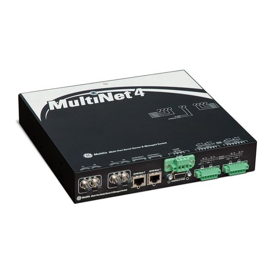
Multinet4 Multi-Port Serial
Server & Managed Switch
Instruction Manual
Manual P/N: 1601-9075-A1 (GEK-113502)
Copyright © 2008 GE Multilin
GE Multilin's Quality Management
System is registered to
ISO9001:2000
QMI # 005094
UL # A3775
Advertisement
Table of Contents

Related Manuals for GE Multinet 4


Summary of Contents for GE Multinet 4
-
Page 1: Instruction Manual
Multilin Multinet4 Multi-Port Serial Server & Managed Switch Instruction Manual Manual P/N: 1601-9075-A1 (GEK-113502) Copyright © 2008 GE Multilin GE Multilin 215 Anderson Avenue, Markham, Ontario, Canada L6E 1B3 Tel: (905) 294-6222, 1-800-547-8629 (North America) Fax: (905) 201-2098 GE Multilin's Quality Management Internet: http://www.GEmultilin.com... - Page 2 The contents of this manual are the property of GE Multilin Inc. This documentation is furnished on license and may not be reproduced in whole or in part without the permission of GE Multilin. The content of this manual is for informational use only and is subject to change without notice.
-
Page 3: Table Of Contents
TABLE OF CONTENTS Table of Contents 1: OVERVIEW CONFIGURATION ..........................1-1 ........................1-1 ONNECTIVITY ......................1-2 OWER AND ROUND .......................... 1-2 NDICATORS ......................1-3 OUNTING PTIONS SPECIFICATIONS ..........................1-4 ..........................1-4 HYSICAL ......................... 1-4 NVIRONMENTAL ........................... 1-4 ESTS ...................... 1-6 OWER EQUIREMENTS ................ - Page 4 TABLE OF CONTENTS Connecting Single-mode Fiber Optics .............2 - 15 MAINTENANCE ..........................2-16 4 ....................2-16 EMOVING THE ULTINET Disconnecting Power and Ground Lines ............2 - 16 Disconnecting Network Cables ................2 - 16 Packing the Multinet4 for Shipment ..............2 - 17 ..................
- Page 5 TABLE OF CONTENTS Sessions: Active Logins ...................4 - 25 ......................4-26 HANGE ASSWORD ......................4-27 OFTWARE PGRADE ........................4-31 ONFIGURATION Configuration: Files ....................4 - 31 Configuration: Defaults ...................4 - 32 ........................4-34 YSTEM EBOOT EVENTS TASKS ........................... 4-35 ............................. 4-35 Logs: Global Settings ....................4 - 40 Logs: Files ........................4 - 41 ..........................
- Page 6 TABLE OF CONTENTS Ethernet Port ........................4 - 93 IP Flows ..........................4 - 94 SECURITY TASKS ..........................4-96 ........................4-96 ERTIFICATES Certificates: Local ......................4 - 96 Certificates: Trusted ....................4 - 97 ........................4-98 THERNET /SSL .......................... 4-99 ERIAL ........................4-101 ERVER CLI ............................
- Page 7 TABLE OF CONTENTS ....................6-8 ESIGN ONSIDERATIONS Configuring Bridge Settings ..................6 - 8 Configuring Port Settings ..................6 - 9 VLAN ..............................6-10 VLAN ........................6-10 DDING VLAN IDs ........................6 - 10 VLAN M ............6-10 ONFIGURING ORTS FOR EMBERSHIP Port VLAN IDs ......................6 - 10 Tagging ..........................6 - 10 Filtering ...........................6 - 11 Frame Classification and Forwarding ..............6 - 11...
- Page 8 TABLE OF CONTENTS USING MULTINET4 SECURE SERIAL PORTS ................7-12 APPLICATION #4: SERIAL-OVER-SECURE-TCP TUNNEL ..........7-13 TROUBLESHOOTING TERMINAL SERVER SSL CONNECTIONS ........7-15 APPENDIX A: PORT AND WELL KNOWN TCP/UDP NETWORK PORTS ................. A-1 TYPE REFERENCE ICMP TYPES ............................A-5 APPENDIX B: THIRD PARTY GNU LESSER GENERAL PUBLIC LICENSE ................
-
Page 9: Connectivity
Digital Energy Multilin Multinet4 Multi-Port Serial Server & Managed Switch Chapter 1: Overview Overview Configuration The following sections describe the features and requirements of the Multinet4. 1.1.1 Connectivity The Multinet4 is equipped with: • 4 Ethernet Ports • 2 100FX multi/single mode Fiber, LC, ST, and SC •... -
Page 10: Power And Ground
OVERVIEW CHAPTER 1: OVERVIEW 1.1.2 Power and Ground The Multinet4 can be ordered with a high (90 -250 VAC or VDC) or Low (24-48 VDC) voltage power supply. The connection point for the power supply is located at the rear of the chassis. -
Page 11: Mounting Options
CHAPTER 1: OVERVIEW OVERVIEW 1.1.4 Mounting Options There are four mounting options for the Multinet4: • 19” rack mount (see section 2.3.1.2 Mounting in a 19” Rail System - General2.3.1.2 Mounting in a 19” Rail System - General) • 19” rack reverse mount (see section 2.3.1.4 Mounting in a 19” Rail System - Reverse Mounting) •... -
Page 12: Specifications
OVERVIEW CHAPTER 1: OVERVIEW Specifications The following sections provide detailed information about the physical, electronic, and industrial specifications of the Multinet4. 1.2.1 Physical The physical dimensions and weight of the Multinet4 are defined in the table below. Table 1–1: Physical Specifications Height: 1.75 inches (4.45 cm) Width:... - Page 13 CHAPTER 1: OVERVIEW OVERVIEW Standard Number:Date Standard Name Severity levels Tested code Power Transients (low repetition high NEMA TS2 :2003 600V, 1 Ohm impedance energy) Transients I/O terminals NEMA TS2 2.1.7.1 :2003 300V, 100 Ohms impedance Serial: 4 kV on shield; Surge Immunity IEC61000-4-5:2005 DC Power LO: 6kV L-E, 6kV L-L;...
-
Page 14: Power Requirements
OVERVIEW CHAPTER 1: OVERVIEW Standard Number:Date Standard Name Severity levels Tested code Dry Heat Temperature EN/IEC 60068-2-2: 1994,1974 +85 deg startup for 16 hours Humidity NEMA TS2 2.1.5 -34 to 74C, 10-95% MECHANICAL TESTS Sinusoidal Vibration EN/IEC 60255-21-1: 1996,1988 Class 1 - 10-150hz @2G Class 2 - 30G bump, 17G Shock and Bump EN/IEC 60255-21-2: 1996,1988... -
Page 15: Ports And External Connectors
CHAPTER 1: OVERVIEW OVERVIEW Table 1–3: Power Requirements High Voltage AC/DC Low Voltage DC Typical Power (Watts): Max. Amperage (Amps): 1.2.5 Ports and External Connectors The ports and external connectors of the Multinet4 are defined in the table below. Table 1–4: Ports and External Connectors Port Name Connector Description... - Page 16 OVERVIEW CHAPTER 1: OVERVIEW Table 1–5: Indicators LED Name Condition Indication S1 – S4 Green Port is connected to an active serial device. (Serial Ports) Port is down. Flashing Data is passing through the port. E1 – E4 Green Port is connected to an active Ethernet device. (Ethernet Ports) Port is down.
-
Page 17: Pinouts
CHAPTER 1: OVERVIEW OVERVIEW Pinouts The following subsections describe the pinouts of the connectors used with the Multinet4. 1.3.1 RJ45 Defines the pinout of the RJ45 connector used with the Multinet4. RJ45 connectors are used on ports E3 and E4 for 10/100 BaseT connections to copper Ethernet-capable devices. -
Page 18: Db9 (Female) - Console Port
OVERVIEW CHAPTER 1: OVERVIEW Table 1–7: LC Pinout Port Signal Transmit Receive 1.3.3 DB9 (Female) – Console Port The figure below defines the pinout of the DB9 female connector for the console port for asynchronous or bit-oriented connections. Table 1–8: DB9 Pinout Name Dir. -
Page 19: Phoenix Connectors - Serial Ports
CHAPTER 1: OVERVIEW OVERVIEW Signal NC1 - normally closed 1 COM1 - common 1 NO1 - normally opened 1 1.3.5 Phoenix Connectors – Serial Ports The figure below defines the pinout of the Phoenix 6-pin connector used with serial ports on the Multinet4. -
Page 20: Features And Benefits
OVERVIEW CHAPTER 1: OVERVIEW Features and Benefits Multinet4 Multi-Port Serial Server & Managed Switch provides secure multiprotocol networking in compact, rugged packages purpose-built for power utility substations and other harsh environments. Cyber-security protection is assured by encrypted per- connection SSL, and port security features. 1.4.1 Multinet4 Multi-Port Serial Server &... -
Page 21: Features Summary
CHAPTER 1: OVERVIEW OVERVIEW 1.4.2 Features Summary The table below summarizes the hardware features of the Multinet4. Table 1–10: Hardware Features Summary Feature Details Connectivity • 4 Ethernet ports 2 100FX multi/single mode Fiber, ST, SC, and — 2 10/100 BaseT, RJ45 Auto-Negotiation and —... - Page 22 OVERVIEW CHAPTER 1: OVERVIEW Table 1–11: Software Features Summary Feature Details Terminal Server • Active, passive, and mixed connection modes • Telnet and raw TCP sessions • Multiple incoming connections per serial port Ethernet Port Management • Supported media types include 10/100BaseTX and 100FX •...
- Page 23 CHAPTER 1: OVERVIEW OVERVIEW Table 1–11: Software Features Summary Feature Details Embedded Web Server • Primary User Interface (HTTP/HTTPS) • Compatible with standard web browsers (such as Internet Explorer or Firefox) User Account Management • Configurable security policies • Up to 16 user accounts •...
- Page 24 OVERVIEW CHAPTER 1: OVERVIEW 1–16 MULTINET4 MULTI-PORT SERIAL SERVER & MANAGED SWITCH – INSTRUCTION MANUAL...
-
Page 25: Installation
Digital Energy Multilin Multinet4 Multi-Port Serial Server & Managed Switch Chapter 2: Getting Started Getting Started The Multinet4 Multi-Port Serial Server & Managed Switch provides connectivity to asynchronous and Ethernet traffic through four programmable serial ports, two 10/100 BaseT Ethernet ports for copper line connections, and two 100FX multimode (MM) or singlemode (SM) for fiber optic connections. -
Page 26: Wiring And Grounding Guidelines
GETTING STARTED CHAPTER 2: GETTING STARTED 2.1.3 Wiring and Grounding Guidelines The Multinet4 requires several different types of connectors, cables, and wires. Requirements and recommendations are listed below: Fiber The fiber cables connected to the Multinet4 must be: • non-dispersion shifted, single mode (SM) •... -
Page 27: Fiber Optic Handling
CHAPTER 2: GETTING STARTED GETTING STARTED 2.1.5 Fiber Optic Handling Contamination from dust, dirt, oils from the hands and other sources can impede the transmission and reception of optical signals through the optical fibers.When handling the optical connectors and fiber cables, follow these precautions to minimize the contamination of the connectors and ports: •... -
Page 28: Unpacking
Be sure that all the equipment you have ordered is included in the shipment. Remove the unit from the styrofoam end caps and inspect the Multinet4 chassis for dents or other shipping related damage. Report any damage immediately to GE Multilin Customer Support and DO NOT INSTALL the unit. -
Page 29: Installation Of The Multinet4 Unit
CHAPTER 2: GETTING STARTED GETTING STARTED Installation of the Multinet4 Unit To install the Multinet4 you must first • Mount it • Make the ground and power connections. • Connect the network cables 2.3.1 Mounting Before mounting, please note the following: Elevated Operating Ambient - If installed in a closed or multi-unit rack assembly, the operating ambient temperature of the rack environment may be greater than room ambient. -
Page 30: Mounting In A 19" Rail System - Conventional Mounting
GETTING STARTED CHAPTER 2: GETTING STARTED FIGURE 2–1: Top View: 19” Rail Conventional and Reverse Mounting 2.3.1.3 Mounting in a 19” Rail System - Conventional Mounting The brackets for mounting in a 19-inch rail system attach with two screws to the screw holes located toward the front of the Multinet4. -
Page 31: Mounting In A 19" Rail System - Reverse Mounting
CHAPTER 2: GETTING STARTED GETTING STARTED FIGURE 2–2: 19” Rail Conventional Mounting brackets 18.9in (48cm) 4.75in (12.07cm) 4.75in (12.07cm) 9.4in (23.9cm) 1.7in 1.25in ALARM (4.32cm) (3.18cm) CONSOLE 18.2in (46.2cm) FIGURE 2–3: 19” Rail Conventional Mounting - Dimensional Drawing 2.3.1.4 Mounting in a 19” Rail System - Reverse Mounting The brackets provided for reverse mounting have an opening in their forward projecting parts to accommodate the power cable. -
Page 32: Mounting On A Panel
GETTING STARTED CHAPTER 2: GETTING STARTED FIGURE 2–4: 19” Rail Reverse Mounting brackets 18.9in (48cm) 4.75in (12.07cm) 4.75in (12.07cm) 9.4in (23.9cm) 1.7in 1.25in DX800-01-L-P (4.32cm) Serial No: (3.18cm) 0650 0034 18.2in (46.2cm) FIGURE 2–5: 19” Rail Reverse Mounting - Dimensional Drawing 2.3.1.5 Mounting on a Panel The brackets for mounting on a panel attach with two screws to the screw holes located toward the rear of the Multinet4. - Page 33 CHAPTER 2: GETTING STARTED GETTING STARTED FIGURE 2–6: Panel Mounting brackets 12.7in (32.26cm) 11.1in (28.2cm) 9.4in (23.88cm) 0.5in (1.27cm) 0.5in (1.27cm) 0.85in (2.16cm) 1.65in (4.2cm) FIGURE 2–7: Panel Mounting - Dimensional Drawing MULTINET4 MULTI-PORT SERIAL SERVER & MANAGED SWITCH – INSTRUCTION MANUAL 2–9...
-
Page 34: Mounting In A Din Rail System
GETTING STARTED CHAPTER 2: GETTING STARTED 2.3.1.6 Mounting in a DIN Rail System The DIN rail bracket rides on the bottom of the Multinet4 and is attached with four screws into the two pair of screw holes located toward the back of the Multinet4. The bracket attaches to the DIN rail by means of a pair of stationary prongs near the top of the bracket and a single spring-loaded prong (the release mechanism) toward the bottom of the bracket. -
Page 35: Connecting Facility Power
CHAPTER 2: GETTING STARTED GETTING STARTED 2.43in 9.4in (23.88cm) (6.17cm) 1.7in < > (4.32cm) <-><-> .35in .38in (.95cm) FIGURE 2–9: DIN Rail Mounting - Dimensional Drawing 2.3.2 Connecting Facility Power The Multinet4 comes in either high or low voltage models. The unit does not have a power on/off switch and is active when the power is connected. - Page 36 GETTING STARTED CHAPTER 2: GETTING STARTED FIGURE 2–10: Ground and Power Connections ELECTRICAL WARNING: Verify that a proper ground connection is made from the ground lug to facility ground prior to connecting power to the Multinet4. Failure to have a proper ground path could cause serious injury or death to personnel in cases of power surges.
-
Page 37: Connecting To The Console Port And The Alarm Port
CHAPTER 2: GETTING STARTED GETTING STARTED Re-insert the plug into the power connector and secure the two captive mounting screws. saddle screws captive mounting screws terminal holes FIGURE 2–11: Non-Polarized Power Input 2.3.3 Connecting to the Console Port and the Alarm Port 2.3.3.1 Console Port Use a DB9 null-modem cable or a DB9-to-USB null-modem cable, to connect the Multinet4 console port (the RS232 port) to the PC. -
Page 38: Connecting Rj45 Twisted Pair
GETTING STARTED CHAPTER 2: GETTING STARTED Tighten the saddle screws until the wires are secure. Re-insert the plug into the phoenix connector and secure the two captive mounting screws. Serial cables must be shielded. It is recommended that high quality Belden 9843 cables be Note used whenever possible to provide reliable serial communication. -
Page 39: Connecting Sc-Type Or Lc-Type Fiber Optics (Snap-In)
CHAPTER 2: GETTING STARTED GETTING STARTED Connect the receive (RX) port on the module (dark colored post) to the transmit (TX) port of the remote device. Use the non-color coded fiber strand. The LINK LED on the module will illuminate when a connection has been established at both ends (assuming power is ON). -
Page 40: Maintenance
GETTING STARTED CHAPTER 2: GETTING STARTED Maintenance The Multinet4 is designed to be replaced as a unit. There are no servicing requirements and there are no user-repairable components in this device. Maintenance is limited to replacing the unit and cleaning any fiber optic connectors and ports. The following sections detail disconnecting all connections to the chassis, removing the chassis, cleaning optical devices and packing the Multinet4 for return to the manufacturer. -
Page 41: Packing The Multinet4 For Shipment
If you have not saved the original shipping container then place the unit in a box so that normal shipping activities will not cause any damage to the unit. GE Multilin has no responsibility for the product during return shipping. -
Page 42: Cleaning Optical Ports
GETTING STARTED CHAPTER 2: GETTING STARTED 2.4.2.2 Cleaning Optical Ports These instructions are recommended only when there is evidence of contamination or when reduced performance has been detected. Clean the optical ports as follows: If required, remove the fiber optic connector from the optical port and clean the connector as described in “Cleaning Connectors,”... -
Page 43: Software Management
CHAPTER 2: GETTING STARTED GETTING STARTED Software Management The EnerVista Multinet4 Setup software or the Web Administrator interface or CLI interface can be used to manage and configure the Multinet4. The EnerVista Multinet4 Setup software is the preferred method to edit the most common used setting. The setup software connects to the unit through the Ethernet port. - Page 44 GETTING STARTED CHAPTER 2: GETTING STARTED Click Save to configure the new IP address information to the Multinet4, wait until the new IP address is read back and showing in the IP Address field as shown below. 2–20 MULTINET4 MULTI-PORT SERIAL SERVER & MANAGED SWITCH – INSTRUCTION MANUAL...
- Page 45 CHAPTER 2: GETTING STARTED GETTING STARTED Click Read Order Code to connect the Multinet4 to read the Order Code and firmware Version. The information will display if the new IP address has been configured successfully.. Click OK to exit Device Setup. MULTINET4 MULTI-PORT SERIAL SERVER &...
-
Page 46: The Enervista Multinet4 Setup Software Overview
GETTING STARTED CHAPTER 2: GETTING STARTED The EnerVista Multinet4 Setup Software Overview The EnerVista Multinet4 Setup software interface is the preferred method to manage and configure the system. Its main window supports the following primary display components: Title bar which shows the pathname of the active data bar. Main window tool bar. -
Page 47: The Advanced Setting - Administrator Interface Overview
CHAPTER 2: GETTING STARTED GETTING STARTED The Advanced Setting - Administrator Interface Overview The Advanced Setting - Administrator Interface enables you to view and edit system parameters through the embedded web browser. 2.7.1 Logging in for the First Time For the first time logging, the secure site will issue the certificate check shown below. FIGURE 2–12: Security certificate Once you click Yes on the security certificate, the browser will prompt you to login. - Page 48 GETTING STARTED CHAPTER 2: GETTING STARTED For Windows VISTA, the browser may show a warning message of “Problem with website Note security certificate”. You will need to regenerate the Multinet4 web server certificate, then import that certificate into IE by following these steps: At the screen - "There is a problem with this website's security certificate,"...
-
Page 49: Administrator Interface Overview
CHAPTER 2: GETTING STARTED GETTING STARTED 17. Click on the View Certificate link. A new dialog called "Certificate" will pop up. 18. Click the "Install Certificate..." button. A wizard dialog will appear. 19. Click the Next button. 20. Select Automatically select the certificate store based on the type of certificate and press the Next button. - Page 50 GETTING STARTED CHAPTER 2: GETTING STARTED Navigation Area Interaction Area Global Area FIGURE 2–14: Administrator Interface Table 2–1: The Administrator Interface Area Name Area Function Navigation The Navigation area contains a menu tree that can be expanded or collapsed to show all of the available interaction screens.
- Page 51 CHAPTER 2: GETTING STARTED GETTING STARTED Table 2–1: The Administrator Interface Area Name Area Function Interaction The Interaction area contains an HTML form where you can configure some aspect of the system. This area can also be used to display read-only information such as port statistics or event logs.
-
Page 52: The Administrator Interface Navigation Tree
GETTING STARTED CHAPTER 2: GETTING STARTED 2.7.3 The Administrator Interface Navigation Tree The menu tree supported in this release is as follows: Table 2–2: Menu Tree Screen Function Virtual Front Panel An animated view of the device’s ports and LEDs Administration Tasks System System Information... - Page 53 CHAPTER 2: GETTING STARTED GETTING STARTED Table 2–2: Menu Tree Screen Function Software Upgrade Install a newer version of software. Configuration View and manage available configuration files. Configuration: Files Configuration: Defaults Restore the system’s default configuration. System Reboot Shut down and restart the system. Events Tasks Logs Enable logging of events and control logfile number and size.
- Page 54 GETTING STARTED CHAPTER 2: GETTING STARTED Table 2–2: Menu Tree Screen Function VLAN Enable/disable VLAN functionality. VLAN: Global Settings Assign VLAN IDs and view properties (tagged/untagged) of existing VLAN: VIDs VIDs. Assign ports to VLANs and set properties (mode, tagged/untagged) VLAN: Port Settings Serial Tasks Ports...
- Page 55 CHAPTER 2: GETTING STARTED GETTING STARTED Table 2–2: Menu Tree Screen Function Security Tasks Certificates Install and view PEM certificate files. Certificates: Local Upload X.509 certificates. Certificates: Trusted Upload and mark as trusted X.509 certificates. Ethernet Port Configure conditions for a security lockout on an Ethernet port. Serial/SSL Configure Secure Sockets Layer for a serial port.
- Page 56 GETTING STARTED CHAPTER 2: GETTING STARTED 2–32 MULTINET4 MULTI-PORT SERIAL SERVER & MANAGED SWITCH – INSTRUCTION MANUAL...
-
Page 57: 3: Enervista Multinet4 Setup Software
Digital Energy Multilin Multinet4 Multi-Port Serial Server & Managed Switch Chapter 3: EnerVista Multinet4 Setup Software EnerVista Multinet4 Setup Software The EnerVista Multinet4 Setup software is the preferred method to edit the most common used setting. PC Requirements The following requirements must be met to ensure correct operation of the EnerVista MultiNet4 setup software: •... -
Page 58: Installation
CHAPTER 3: ENERVISTA MULTINET4 SETUP SOFTWARE Installation After ensuring the minimum requirements for using EnerVista Multinet4 Setup are met, use the following procedure to install the EnerVista Multinet4 Setup from the enclosed GE EnerVista CD. Insert the GE EnerVista CD into your CD-ROM drive. -
Page 59: Configuring Ethernet Communication
Multinet4’s IP address. • Verify that the latest version of the EnerVista Multinet4 Setup software is installed (available from the GE EnerVista CD or online from http://www.GEmultilin.com). See the Software Installation section for installation details. To setup the Multinet4 for Ethernet communications, it will be necessary to define a Site, and then add the Multinet4 as a Device at that site. - Page 60 ENERVISTA MULTINET4 SETUP SOFTWARE CHAPTER 3: ENERVISTA MULTINET4 SETUP SOFTWARE Select “Ethernet” from the Interface drop-down list. This will display a number of interface parameters that must be entered for proper Ethernet functionality. Enter the Multinet4 IP address in the “IP Address” field. If a new IP address is desired at this point, the new IP address should be entered in the New IP Address field in the Network Setting frame, and the current IP Address in the IP Address field.
- Page 61 CHAPTER 3: ENERVISTA MULTINET4 SETUP SOFTWARE ENERVISTA MULTINET4 SETUP SOFTWARE will not be able to see port settings in the online tree. However you can still access the device through the Settings > Advanced Settings window of the online device in the Setup Software. The login credentials policy is also applied when using Quick Connect, while saving Note settings to switch from Online configuration screens, while saving settings from offline file...
-
Page 62: Using The Quick Connect Feature
ENERVISTA MULTINET4 SETUP SOFTWARE CHAPTER 3: ENERVISTA MULTINET4 SETUP SOFTWARE Using the Quick Connect Feature If you need to start talking to a Multinet4 device quickly, Press the Quick Connect button, to start the Quick Connect. Click the Quick Connect button to open the Quick Connect dialog box. Enter the IP address assigned to the Multinet4, then click Connect. -
Page 63: Connecting To The Multinet4
CHAPTER 3: ENERVISTA MULTINET4 SETUP SOFTWARE ENERVISTA MULTINET4 SETUP SOFTWARE Connecting to the Multinet4 After Device Setup or Quick Connect completed, a site list tree will show on the left side of the EnerVista Multinet4 Setup window. In this example, Ethernet port setting window will open by clicking the Ethernet under Setting >... -
Page 64: Port Setting
ENERVISTA MULTINET4 SETUP SOFTWARE CHAPTER 3: ENERVISTA MULTINET4 SETUP SOFTWARE Port Setting Ethernet port setting: Ethernet setting window will open by clicking the Ethernet under Setting > Ports as shown below. The system IP address, subnet mask and gateway address of the Multinet4 can be configured on this screen. - Page 65 CHAPTER 3: ENERVISTA MULTINET4 SETUP SOFTWARE ENERVISTA MULTINET4 SETUP SOFTWARE Please refer to Chapter 4 in this manual for the advanced setting for Serial Ports. Note MULTINET4 MULTI-PORT SERIAL SERVER & MANAGED SWITCH – INSTRUCTION MANUAL 3–9...
-
Page 66: Advanced Setting
ENERVISTA MULTINET4 SETUP SOFTWARE CHAPTER 3: ENERVISTA MULTINET4 SETUP SOFTWARE Advanced Setting The EnerVista Multinet4 Setup allow user to login the web interface of Multinet4 by clicking the Advance Setting through the Site List tree. An embedded web browser window will open with a status indicator. The Multinet4 Web Management Logon screen will appear as shown below. -
Page 67: Firmware Upgrade
CHAPTER 3: ENERVISTA MULTINET4 SETUP SOFTWARE ENERVISTA MULTINET4 SETUP SOFTWARE Firmware Upgrade The Enervista Multinet4 Setup software or the Web interface or CLI interface or can be used to upgrade the firmware for the Multinet4. The EnerVista Multinet4 Setup software is the preferred method because it is much less error prone. -
Page 68: Off-Line Feature
ENERVISTA MULTINET4 SETUP SOFTWARE CHAPTER 3: ENERVISTA MULTINET4 SETUP SOFTWARE Off-line Feature The EnerVista Multinet4 Setup software interface supports three ways of handling changes to device settings: • In off-line mode (device disconnected) to create or edit device settings files for later download to communicating devices. -
Page 69: Writing Settings To A Device
CHAPTER 3: ENERVISTA MULTINET4 SETUP SOFTWARE ENERVISTA MULTINET4 SETUP SOFTWARE files for a previously created EnerVista Multinet4 Setup file with the extension XML as the desired target. If no settings files have been previously created, then create a Settings List File. ... -
Page 70: Configure A New Ip Address Through Console Port
ENERVISTA MULTINET4 SETUP SOFTWARE CHAPTER 3: ENERVISTA MULTINET4 SETUP SOFTWARE 3.10 Configure a New IP Address through Console Port The Multinet4 Serial Port Server is delivered with a default IP address 192.168.1.2. The user must change this address to one that is valid on the user’s network. The Multinet4 Setup software provides a way to configure a new IP through the Multinet4’s Console Port. -
Page 71: Virtual Front Panel
Digital Energy Multilin Multinet4 Multi-Port Serial Server & Managed Switch Chapter 4: System Administration System Administration This chapter describes the specific functionality of the Multinet4’s supervisory software. For an overview of the interface features see section 2.7: The Advanced Setting - Administrator Interface Overview. -
Page 72: Administration Administration Tasks
SYSTEM ADMINISTRATION CHAPTER 4: SYSTEM ADMINISTRATION Administration Tasks The following subsections describe the tasks that you can perform using the screens of the Administration branch. 4.2.1 System You can view identifying information about your system in the System Information screen and monitor system status in the System Status screen, both shown below. -
Page 73: System Status
CHAPTER 4: SYSTEM ADMINISTRATION SYSTEM ADMINISTRATION Table 4–1: System Information Field Name Field Value System Contact: Configurable MIB-II system contact of up to 256 printable characters. System Description: The system model number and current software version. Upgrade State: The current software upgrade state. IP Address: The system IP address. -
Page 74: Time
SYSTEM ADMINISTRATION CHAPTER 4: SYSTEM ADMINISTRATION Table 4–2: System: Status Field Name Field Value System Memory Utilization: The percentage of dynamic system memory currently in use. Ethernet-CPU Buffer Utilization: The software maintains a fixed size queue of buffers for received ethernet frames. This parameter is the percentage of these buffers currently holding a received frame that has not yet been processed by the IP stack or other network application. -
Page 75: Time: Zone And Dst
CHAPTER 4: SYSTEM ADMINISTRATION SYSTEM ADMINISTRATION • If SNTP is enabled and a server is reachable, the system time and date will be refreshed from the server upon power up. 4.2.4.2 Time: Zone and DST This screen enables you to specify the standard time for your location as an offset from Universal Coordinated Time (UTC) and to specify the part of the year during which Daylight Savings Time (DST) will be in effect. -
Page 76: Time: Persistence
SYSTEM ADMINISTRATION CHAPTER 4: SYSTEM ADMINISTRATION The table below describes the parameters you can view and edit in the Time: Zone and DST screen. Table 4–4: Time: Zone and DST Field Name Field Value Standard Time=UTC: Your offset from the UTC. Value is in hours:minutes. Range is from -12:59 to 12:59 Examples: UTC Offsets Zone... -
Page 77: Sntp
CHAPTER 4: SYSTEM ADMINISTRATION SYSTEM ADMINISTRATION from the network. However, if the time and date were set to some time and date from the recent past, the VPN authentication would succeed, the tunnel would be established, and the Multinet4 would be able to resynchronize its time with the NTP server. FIGURE 4–5: Administration: Time: Persistence The table below specifies the parameter that you can set in the Time: Persistence screen. -
Page 78: Sntp: Servers
SYSTEM ADMINISTRATION CHAPTER 4: SYSTEM ADMINISTRATION Table 4–6: SNTP Global Settings Field Name Field Value Mode: Indicates if and how the SNTP client should be used to set the system's time and date information.This parameter takes one of the following values: •... -
Page 79: Snmp
CHAPTER 4: SYSTEM ADMINISTRATION SYSTEM ADMINISTRATION The table below describes the fields of the SNTP: Servers screen to add and delete SNTP servers. Table 4–7: SNTP Servers Field Name Field Value Add Server Form Server IP: Enter the IP address of an SNTP server to be accessed. Click Apply Settings to add this server to the Existing SNTP Servers Table. - Page 80 SYSTEM ADMINISTRATION CHAPTER 4: SYSTEM ADMINISTRATION The table below describes the parameters you can view and configure in the “SNMP: Global Settings” screen. Table 4–8: SNMP: Global Settings Field Name Field Value Mode: Enable or disable SNMP agent. • Disabled – agent does not respond to queries. •...
-
Page 81: Snmp: Management Stations
CHAPTER 4: SYSTEM ADMINISTRATION SYSTEM ADMINISTRATION Table 4–8: SNMP: Global Settings Field Name Field Value Engine Boots: The number of times the system has booted since the current engine ID was set. Engine Time: The number of seconds elapsed since the engine ID was changed or the system booted, whichever occurred most recently. -
Page 82: Snmp: Trap Stations
SYSTEM ADMINISTRATION CHAPTER 4: SYSTEM ADMINISTRATION Table 4–9: SNMP: Management Stations Field Name Field Value Existing Stations Table IP Address: This table lists the IP addresses of management stations that have been configured in the system. Delete: Set the Delete checkbox in a row and click Apply Settings to delete that management station 4.2.6.3 SNMP: Trap Stations This screen enables you add trap stations (up to a total of 4) and to view and edit the... -
Page 83: Snmp: Users
CHAPTER 4: SYSTEM ADMINISTRATION SYSTEM ADMINISTRATION Table 4–10: SNMP: Trap Stations Field Name Field Value Security Name: When the agent is enabled for v3 mode this is the name of an SNMP user. The trap will be sent with security mode and auth/ priv passwords of that user. - Page 84 SYSTEM ADMINISTRATION CHAPTER 4: SYSTEM ADMINISTRATION Table 4–11: SNMP: Users Field Name Field Value Auth Password: Enter a password to be used for generating the authentication keys. Allowed password length is 8 to 40 characters. Retype Password: Re-type the authentication password to confirm it. Privacy Password: Enter a password to be used for generating the encryption keys.
-
Page 85: Snmp: Statistics
CHAPTER 4: SYSTEM ADMINISTRATION SYSTEM ADMINISTRATION 4.2.6.5 SNMP: Statistics This screen below allows you to view detailed SNMP performance statistics. FIGURE 4–12: Administration: SNMP: Statistics The table below describes the values you can view in the SNMP: Statistics screen. MULTINET4 MULTI-PORT SERIAL SERVER & MANAGED SWITCH – INSTRUCTION MANUAL 4–15... - Page 86 SYSTEM ADMINISTRATION CHAPTER 4: SYSTEM ADMINISTRATION Table 4–12: SNMP: Statistics Field Name Field Value In Packets: The total number of messages delivered to the SNMP entity from the transport service. Bad Versions: The total number of SNMP messages which were delivered to the SNMP protocol entity and were for an unsupported SNMP version.
- Page 87 CHAPTER 4: SYSTEM ADMINISTRATION SYSTEM ADMINISTRATION Table 4–12: SNMP: Statistics Field Name Field Value Out Bad Values: The total number of SNMP PDUs which were generated by the SNMP protocol entity and for which the value of the error-status field is “badValue.” In Read Onlys: The total number valid SNMP PDUs which were delivered to the SNMP protocol entity and for which the value of the error-status...
- Page 88 SYSTEM ADMINISTRATION CHAPTER 4: SYSTEM ADMINISTRATION Table 4–12: SNMP: Statistics Field Name Field Value In Total Set Vars: The total number of MIB objects which have been altered successfully by the SNMP protocol entity as the result of receiving valid SNMP Set-Request PDUs. Silent Drops: The total number of GetRequest PDUs, GetNextRequest PDUs,GetBulkRequest PDUs, SetRequest PDUs, and...
-
Page 89: Authentication
CHAPTER 4: SYSTEM ADMINISTRATION SYSTEM ADMINISTRATION Table 4–12: SNMP: Statistics Field Name Field Value Not In Time Windows: The total number of packets received by the SNMP engine which were dropped because they appeared outside of the authoritative SNMP engine's window. Unknown Usernames: The total number of packets received by the SNMP engine which were dropped because they referenced a user that was... - Page 90 SYSTEM ADMINISTRATION CHAPTER 4: SYSTEM ADMINISTRATION Violations of security settings such as: failed login attempts or inactive user expiration Note result in a "lock out" state. Only administrators may clear this state. Table 4–13: Authentication: Policies Field Name Field Value Bad login attempts The number of consecutive failed login attempts before a user is before lockout:...
- Page 91 CHAPTER 4: SYSTEM ADMINISTRATION SYSTEM ADMINISTRATION Table 4–13: Authentication: Policies Field Name Field Value Password Ageing Newly created accounts that are not part of the administration (Days): group can optionally expire passwords by setting this value to the number of days a password is valid before a change is required.
-
Page 92: Authentication: Accounts
SYSTEM ADMINISTRATION CHAPTER 4: SYSTEM ADMINISTRATION 4.2.7.2 Authentication: Accounts The Authentication “User Accounts” enables an administrator to add and delete users and to maintain certain account information. FIGURE 4–14: Administration: Authentication: Accounts By factory default, there is a single administrator account with the login name “manager” and password “manager”. - Page 93 CHAPTER 4: SYSTEM ADMINISTRATION SYSTEM ADMINISTRATION Table 4–14: Authentication: Accounts Field Name Field Value Group Name: Use the drop-down list to assign this user to one of three privilege levels. The privilege levels are: • Admin: Members of this group may perform all functions including managing software, user accounts, and configuration files.
-
Page 94: Authentication: Files
SYSTEM ADMINISTRATION CHAPTER 4: SYSTEM ADMINISTRATION 4.2.7.3 Authentication: Files This page enables you to upload new user definitions. FIGURE 4–15: Administration: Authentication: Files Table 4–15: Authentication: Files Field Name Field Value Browse: To install a new user definition file: 1. Browse to a file on you local system, or enter the full path name of a user definition file. -
Page 95: Sessions
CHAPTER 4: SYSTEM ADMINISTRATION SYSTEM ADMINISTRATION 4.2.8 Sessions The sessions screens enable you to set login session policies and to monitor active logins. 4.2.8.1 Sessions: Policies This screen enables you to set up the system's session management policies. FIGURE 4–16: Administration: Sessions: Polices The table below describes the parameter you can configure in the Sessions: Polices screen. -
Page 96: Change Password
SYSTEM ADMINISTRATION CHAPTER 4: SYSTEM ADMINISTRATION The table below describes the information displayed in the Sessions: Active Logins screen. Table 4–17: Sessions: Active Logins Field Name Field Value Session: A unique identifier for a session. Username: The username that is logged in. Client Host: The IP address of the remote client. -
Page 97: Software Upgrade
CHAPTER 4: SYSTEM ADMINISTRATION SYSTEM ADMINISTRATION Table 4–18: Change Password Field Name Field Value Password: Enter the new password here. Characters in the password are always echoed back as the bullet character ( ). The field length minimum is 6 alphanumeric characters. Re-Type Password: Confirm the initial password entry by re-typing it in this field. - Page 98 SYSTEM ADMINISTRATION CHAPTER 4: SYSTEM ADMINISTRATION Software Upgrade States The figure and table below describe the entire software upgrade finite state machine. FIGURE 4–19: Software Upgrade State Machine Table 4–19: Upgrade States and User Actions Event Description New Software User copies a valid software image. Reboot User reboots the system.
- Page 99 CHAPTER 4: SYSTEM ADMINISTRATION SYSTEM ADMINISTRATION The figure below depicts an Administration: Software Upgrade window after a successful upgrade. FIGURE 4–20: Administration: Software Upgrade The table below describes the parameters you can view and configure in the Software Upgrade screen. Table 4–20: Software Upgrade Field Name Field Value...
- Page 100 SYSTEM ADMINISTRATION CHAPTER 4: SYSTEM ADMINISTRATION Table 4–20: Software Upgrade Field Name Field Value Existing Images Table Filename: This table displays either one or two filenames. If the value displayed in the Software Upgrade process state table is “INITIAL” then this is the initial software installation and only one filename is displayed.
-
Page 101: Configuration
CHAPTER 4: SYSTEM ADMINISTRATION SYSTEM ADMINISTRATION 4.2.11 Configuration The Configuration: Files and the Configuration: Defaults screens shown below, allow you to make system-wide changes by installing a new system configuration file or by returning to factory defaults. 4.2.11.1 Configuration: Files This screen enables you to install and manage configuration files. -
Page 102: Configuration: Defaults
SYSTEM ADMINISTRATION CHAPTER 4: SYSTEM ADMINISTRATION Table 4–22: Configuration Files Field Name Field Value The Configurations Table Filename: This column lists all configuration files present in the system. Version: This value identifies the software version that was running when the system wrote this configuration file. Fallback: “Yes”... - Page 103 CHAPTER 4: SYSTEM ADMINISTRATION SYSTEM ADMINISTRATION FIGURE 4–22: Administration: Configuration: Defaults Click the Restore button to restore system defaults. MULTINET4 MULTI-PORT SERIAL SERVER & MANAGED SWITCH – INSTRUCTION MANUAL 4–33...
-
Page 104: System Reboot
SYSTEM ADMINISTRATION CHAPTER 4: SYSTEM ADMINISTRATION 4.2.12 System Reboot This Reboot screen enables you to shut down and restart the system. FIGURE 4–23: Administration: System Reboot Click the Reboot button to reset the system. 4–34 MULTINET4 MULTI-PORT SERIAL SERVER & MANAGED SWITCH – INSTRUCTION MANUAL... -
Page 105: Events Tasks
CHAPTER 4: SYSTEM ADMINISTRATION SYSTEM ADMINISTRATION Events Tasks Events are a specified set of actions or attempted actions that are recorded in log files or sent to a visual display to enable a system administrator to monitor system activity. Multinet4 specifies a set of events (see Table 4–23:: Logged Events) that are recorded in log files on the management server. - Page 106 SYSTEM ADMINISTRATION CHAPTER 4: SYSTEM ADMINISTRATION Table 4–23: Logged Events Event Description Account Lockout Account loginname has been locked out for bad logins. A user account, with login name loginname, was suspended because the user entered a password incorrectly too many times in a row. Lockout Ended Suspension timeout has elapsed for user loginname.
-
Page 107: Event Description
CHAPTER 4: SYSTEM ADMINISTRATION SYSTEM ADMINISTRATION Table 4–23: Logged Events Event Description Host Unreachable Serial port Sx reports that the host at ipaddr is unreachable. The terminal server channel for Serial port Sx is configured to call out to a remote host at IP address ipaddr but the system has no route to the destination address. - Page 108 SYSTEM ADMINISTRATION CHAPTER 4: SYSTEM ADMINISTRATION Table 4–23: Logged Events Event Description Certificate Serial port Sx reports that the certificate presented by the host at Problem ipaddr (tcpport) was invalid (problemdescription). The terminal server channel for Serial port Sx is configured for SSL security.
- Page 109 CHAPTER 4: SYSTEM ADMINISTRATION SYSTEM ADMINISTRATION Table 4–23: Logged Events Event Description Sequence IPsec sequence numbers have exceeded the boundary. This event is Number Overflow informational and should cause the tunnel to re-key. Soft Life Time The soft life time for the tunnel has expired. The tunnel will re-key the Expired next time a packet is received that must go through the tunnel.
-
Page 110: Logs: Global Settings
SYSTEM ADMINISTRATION CHAPTER 4: SYSTEM ADMINISTRATION 4.3.1.1 Logs: Global Settings This screen enables you to specify the frequency, number, and size of log files. FIGURE 4–24: Events: Logs: Global Settings The table below specifies the valid values for fields of the Logs: Global Settings form. Table 4–24: Logs: Global Settings Field Name Field Value... -
Page 111: Logs: Files
CHAPTER 4: SYSTEM ADMINISTRATION SYSTEM ADMINISTRATION Table 4–24: Logs: Global Settings Field Name Field Value Max Log File Size Specify the maximum size, in KB, of any log file. If the current log (KB): file becomes full, a new log file is created. Default value = 32KB. -
Page 112: Syslog
SYSTEM ADMINISTRATION CHAPTER 4: SYSTEM ADMINISTRATION FIGURE 4–25: Events: Logs: Files The table below explains how to use the fields in the Logs: Files table. Table 4–25: Logs: Files Field Name Field Value Filename: The names and sizes of log files available for viewing. The log file that is currently active for writing is also flagged under the Status column. -
Page 113: Syslog: Global Settings
CHAPTER 4: SYSTEM ADMINISTRATION SYSTEM ADMINISTRATION deliver notification of syslog events to the specified collector(s). How that information is stored and displayed on the collector is a function of the software running on the collector. There are many freely available software products to manage this task. 4.3.2.1 Syslog: Global Settings This screen enables you to enable syslog functionality. - Page 114 SYSTEM ADMINISTRATION CHAPTER 4: SYSTEM ADMINISTRATION Table 4–24:: Logs: Global Settings describes the parameters you can edit in the Syslog: Collectors screen Table 4–27: Syslog: Collectors Field Name Field Value Add Collector Form Collector IP: The IP address of the server to which syslog messages will be sent.
-
Page 115: Ethernet Tasks
CHAPTER 4: SYSTEM ADMINISTRATION SYSTEM ADMINISTRATION Ethernet Tasks The following subsections describe the tasks that you can perform using the screens of the Ethernet Switching branch. 4.4.1 Ports The Ports screens enable you to configure ports and to view port status and statistics. 4.4.1.1 Ports: Settings This screen enables you to configure the system’s Ethernet ports. - Page 116 SYSTEM ADMINISTRATION CHAPTER 4: SYSTEM ADMINISTRATION Table 4–28: Ethernet: Ports: Settings Field Name Field Value Media Type: Enables you to force a speed and duplex setting on an Ethernet port or set the port to auto-negotiate mode. Only speed/duplex settings appropriate for the particular interface type are allowed: •...
- Page 117 This is useful for automatic link recovery procedures. This parameter is ignored for copper ports. LLA: The GE Multilin Universal Relay (UR) family, and the F650 family of relays have redundant Ethernet ports that allow automatic switching to their secondary ports when they detect that the primary path is broken.
-
Page 118: Ports: Status
SYSTEM ADMINISTRATION CHAPTER 4: SYSTEM ADMINISTRATION 4.4.1.2 Ports: Status This screen enables you to quickly determine the capabilities and current status of each Ethernet port in the system. FIGURE 4–29: Ethernet: Ports: Status The table below describes the information displayed in the fields of the Ports: Status screen. -
Page 119: Ports: Summary Statistics
CHAPTER 4: SYSTEM ADMINISTRATION SYSTEM ADMINISTRATION Table 4–29: Ethernet: Ports: Status Field Name Field Value Duplex: A READ-ONLY field that indicates the actual duplex of the communication channel. If you selected a particular Media Type in the 4.4.1.1 Ports: Settings screen, the displayed duplex value will match that selection. -
Page 120: Ports: Extended Statistics
SYSTEM ADMINISTRATION CHAPTER 4: SYSTEM ADMINISTRATION Table 4–30: Ethernet: Ports: Summary Statistics Field Name Field Value Port ID: Uniquely identifies an Ethernet interface. Rx Packets: The total number of packets (including bad packets, broadcast packets, and multicast packets) received. Rx Octets: The total number of octets of data (including those in bad packets) received on the network (excluding framing bits but including FCS octets). - Page 121 CHAPTER 4: SYSTEM ADMINISTRATION SYSTEM ADMINISTRATION FIGURE 4–31: Ethernet: Ports: Extended Statistics Table 4–30:: Ethernet: Ports: Summary Statistics describes the parameters viewable in both the Main and the Ports: Extended Statistics screens. Table 4–31: Ethernet: Ports: Extended Statistics Field Name Field Value Rx Octets: The total number of octets of data (including those in bad...
- Page 122 SYSTEM ADMINISTRATION CHAPTER 4: SYSTEM ADMINISTRATION Table 4–31: Ethernet: Ports: Extended Statistics Field Name Field Value Rx Multicast: The total number of good packets received that were directed to a multicast address. Note that this number does not include packets directed to the broadcast address. Rx Pause: Total number of PAUSE frames received.
- Page 123 CHAPTER 4: SYSTEM ADMINISTRATION SYSTEM ADMINISTRATION Table 4–31: Ethernet: Ports: Extended Statistics Field Name Field Value Tx 65to127: The total number of packets transmitted that were between 65 and 127 octets in length inclusive (excluding framing bits but including FCS octets). Tx 128 to255: The total number of packets transmitted that were between 128 and 255 octets in length inclusive (excluding framing bits...
-
Page 124: Ports: Mirroring
SYSTEM ADMINISTRATION CHAPTER 4: SYSTEM ADMINISTRATION Table 4–31: Ethernet: Ports: Extended Statistics Field Name Field Value Filtered: The total number of valid frames received that are not forwarded to a destination port. Discards: The total number of valid frames that were discarded due to lack of buffer space. -
Page 125: Ports: Rate Limits
CHAPTER 4: SYSTEM ADMINISTRATION SYSTEM ADMINISTRATION Table 4–32: Ports: Mirroring Field Name Field Value Port ID: Uniquely identifies a logical Ethernet port that corresponds to a physical, labeled interface on the exterior of the product chassis. The Port ID string should exactly match the physical labeling scheme. -
Page 126: Bridge
SYSTEM ADMINISTRATION CHAPTER 4: SYSTEM ADMINISTRATION Table 4–33: Ethernet: Ports: Rate Limits Field Name Field Value Port ID: Unique port identifier. Ingress Limit Type: This parameter can take one of four parameters: • Broadcast – • Multicast – • Flooded – •... -
Page 127: Bridge: Global Settings
CHAPTER 4: SYSTEM ADMINISTRATION SYSTEM ADMINISTRATION station cache so long as it remains active in the system - a condition that is determined by the “aging interval.” For details see the 4.4.2.1 Bridge: Global Settings screen, and the 4.4.2.3 Bridge: Station Cache screen. Learned –... - Page 128 SYSTEM ADMINISTRATION CHAPTER 4: SYSTEM ADMINISTRATION FIGURE 4–35: Ethernet: Bridge: Static MACs The table below describes the uses of the fields of the Bridge: Static MACs screen. Ethernet: Bridge: Static MACs Table 4–35: Field Name Field Value Add Static MAC Address Form Static Source Specify the static MAC Address of a station to add it to the Address:...
-
Page 129: Bridge: Station Cache
CHAPTER 4: SYSTEM ADMINISTRATION SYSTEM ADMINISTRATION 4.4.2.3 Bridge: Station Cache This screen enables you to view the station cache. The station cache is a database maintained by the Ethernet bridge that tracks MAC addresses of stations on the network and the ports associated with them. This form displays a snapshot of the contents of the Ethernet bridge station cache. -
Page 130: Rstp
SYSTEM ADMINISTRATION CHAPTER 4: SYSTEM ADMINISTRATION Table 4–36: Bridge: Station Cache Field Name Field Value Source Port: Identifies the port associated with the address in the Source Address column. Entry Type: There are three entry types: • Static – Entries that are set by the user. These are not removed automatically. - Page 131 CHAPTER 4: SYSTEM ADMINISTRATION SYSTEM ADMINISTRATION Table 4–37: RSTP: Bridge Settings Field Name Field Value Protocol: Select whether or not to run the Spanning Tree Protocol. This parameter can take one of the following values: • Enabled • Disabled Default value = disabled Priority: Used by the IEEE 802.1d spanning tree algorithm to determine the root of the interconnected network.
-
Page 132: Rstp: Port Settings
SYSTEM ADMINISTRATION CHAPTER 4: SYSTEM ADMINISTRATION 4.4.3.2 RSTP: Port Settings This page enables you to configure port-specific Rapid Spanning Tree Protocol (RSTP) parameters. FIGURE 4–38: Ethernet: RSTP: Port Settings The table below describes the port parameters you can view and configure in the RSTP: Port Settings form. -
Page 133: Rstp: Bridge Status
CHAPTER 4: SYSTEM ADMINISTRATION SYSTEM ADMINISTRATION 4.4.3.3 RSTP: Bridge Status This page enables you to view bridge-specific RSTP counters and status. FIGURE 4–39: Ethernet RSPT: Bridge Status The table below describes the bridge status and counters you can view in the RSTP: Bridge Status table. -
Page 134: Rstp: Port Status
SYSTEM ADMINISTRATION CHAPTER 4: SYSTEM ADMINISTRATION Table 4–39: RSTP: Bridge Status Field Name Field Value Learned Hello Time: The actual Hello Time provided by the root bridge through configuration BPDUs. The learned Hello Time is used in all designated bridges. Configured The locally configured Forward Delay. -
Page 135: Vlan
CHAPTER 4: SYSTEM ADMINISTRATION SYSTEM ADMINISTRATION Table 4–40: RSTP: Port Status Field Name Field Value Port ID: Unique port identifier. State: This parameter can take one of the following values: • Disabled • Blocking • Forwarding • Learning • Listening Role: This parameter can take one of the following values: •... -
Page 136: Vlan: Vids
SYSTEM ADMINISTRATION CHAPTER 4: SYSTEM ADMINISTRATION The table below describes the parameters you can view and configure in the VLANs: Global Settings screen. Table 4–41: VLANs: Global Settings Field Name Field Value Mode: Indicates whether or not the switch is VLAN-aware. •... -
Page 137: Vlan: Port Settings
CHAPTER 4: SYSTEM ADMINISTRATION SYSTEM ADMINISTRATION The table below describes the parameters you can view and configure in the VLAN: VIDs screen. Table 4–42: VLAN: VIDs Field Name Field Value Add VLAN Form VID: A unique numerical identifier assigned to this VLAN. Valid range = 1-4094. - Page 138 SYSTEM ADMINISTRATION CHAPTER 4: SYSTEM ADMINISTRATION FIGURE 4–42: Ethernet: VLAN: Port Settings The table below describes the VLAN parameters you can configure in the Port Settings form. Table 4–43: VLAN: Port Settings Field Name Field Value Port ID: Unique identifier for this port. PVID: This is the native VLAN assigned to this port.
- Page 139 CHAPTER 4: SYSTEM ADMINISTRATION SYSTEM ADMINISTRATION Table 4–43: VLAN: Port Settings Field Name Field Value Tagged? The available options for this field have the following significance: • No – the port strips all VLAN tags before transmitting frames. • Yes – the port ensures that a VLAN tag is present in a frame before transmission.
-
Page 140: Serial Tasks
SYSTEM ADMINISTRATION CHAPTER 4: SYSTEM ADMINISTRATION Serial Tasks The following subsections describe the tasks that you can perform using the screens of the Serial Tasks branch. 4.5.1 Ports The Ports screens enable you to configure and monitor serial ports. 4.5.1.1 Ports: Profiles This screen enables you to add and configure serial port profiles. - Page 141 CHAPTER 4: SYSTEM ADMINISTRATION SYSTEM ADMINISTRATION FIGURE 4–43: Serial: Ports: Profiles The table below describes the parameters in the Ports: Profiles screen. Table 4–44: Ports: Profiles Field Name Field Value Profile Name: A user-assigned name for this profile. When you assign a profile to a port in the 4.5.1.2 Ports: Settings screen, you select this name in the “Profile”...
- Page 142 SYSTEM ADMINISTRATION CHAPTER 4: SYSTEM ADMINISTRATION Table 4–44: Ports: Profiles Field Name Field Value Speed: The baud rate of the port. This parameter may take one of the following values: • 1200 • 2400 • 4800 • 9600 • 19200 •...
- Page 143 CHAPTER 4: SYSTEM ADMINISTRATION SYSTEM ADMINISTRATION Table 4–44: Ports: Profiles Field Name Field Value Flow Control: The type of flow control implemented. This parameter may take one of the following values: • None • XON/XOFF – Software flow control. Unit will stop transmitting if an XOFF (19) character (CTL-S) is detected in the received stream and will start when an XON (17) character (CTL-Q) is detected.
-
Page 144: Ports: Settings
SYSTEM ADMINISTRATION CHAPTER 4: SYSTEM ADMINISTRATION Table 4–44: Ports: Profiles Field Name Field Value T/A Time (ms): This parameter defines a turnaround time for the serial port. The turnaround time is an enforced minimum delay between received network packets that are sent out the serial port. The purpose of the minimum delay is to give legacy RTUs a chance to recover from the previous packet reception. -
Page 145: Ports: Statistics
CHAPTER 4: SYSTEM ADMINISTRATION SYSTEM ADMINISTRATION Table 4–45: Ports: Settings Field Name Field Value Profile: The serial profile assigned to this port. The assigned profile defines all of the communication parameters associated with this serial port. The default value is the default factory profile “Default”. -
Page 146: Terminal Server
SYSTEM ADMINISTRATION CHAPTER 4: SYSTEM ADMINISTRATION Table 4–46: Ports: Statistics Field Name Field Value Breaks: The number of times a break was detected in the middle of receiving a character. A break is detected when an all-zero character with no stop bit is received. Parity Errors: The number of times the calculated parity of a character did not match the configured parity mode. - Page 147 CHAPTER 4: SYSTEM ADMINISTRATION SYSTEM ADMINISTRATION FIGURE 4–46: Serial: Terminal Server: Channel Settings The Add New Channel Form is used to add new Terminal Server channels and to modify parameters for channels that have already been added to the system. Each channel has the capability to make a single outgoing connection and accept multiple incoming connections.
- Page 148 SYSTEM ADMINISTRATION CHAPTER 4: SYSTEM ADMINISTRATION Table 4–47: Terminal Server: Channel Settings Field Name Field Value Port ID: A unique identifier for the serial port being configured. Call Direction: The direction in which the TCP connection will be established. This parameter takes one of the following values: •...
- Page 149 CHAPTER 4: SYSTEM ADMINISTRATION SYSTEM ADMINISTRATION Table 4–47: Terminal Server: Channel Settings Field Name Field Value Remote IP The remote IP address that the client attempts to connect to when the direction is set to “Out” or “Both”. This parameter may be set to any IP address.
-
Page 150: Terminal Server: Channel Status
SYSTEM ADMINISTRATION CHAPTER 4: SYSTEM ADMINISTRATION 4.5.2.2 Terminal Server: Channel Status This screen enables you to view the current status of each Terminal Server Channel. FIGURE 4–47: Serial: Terminal Server: Channels Status The Terminal Server: Channel Status screen is similar to the 4.5.2.1 Terminal Server: Channel Settings screen. -
Page 151: Terminal Server: Connections
CHAPTER 4: SYSTEM ADMINISTRATION SYSTEM ADMINISTRATION Table 4–48: Terminal Server: Channel Status Field Name Field Value State: The state of the channel. This field may display one of the following values: • Inactive: The channel is disabled because the associated serial port is disabled or down. -
Page 152: Modbus
SYSTEM ADMINISTRATION CHAPTER 4: SYSTEM ADMINISTRATION The table below describes the parameters displayed in the Terminal Server: Connections screen. Table 4–49: Terminal Server: Connections Field Name Field Value Port ID: A unique identifier for this serial port. Connection Type: Indicates whether or not the connection is encrypted and if so, which cipher is being used. -
Page 153: Fixed Mappings
CHAPTER 4: SYSTEM ADMINISTRATION SYSTEM ADMINISTRATION Field Name Field Value Modbus Management Whether or not the Multinet4 memory map is accessible Management Address The Modbus device address used to access the Multinet4 memory map 4.5.3.2 Fixed Mappings Allows the user to enable fixed mappings between serial ports and Modbus/TCP ports. This screen is used to define the directly connected Modbus Master devices. -
Page 154: Modbus: Local Masters
SYSTEM ADMINISTRATION CHAPTER 4: SYSTEM ADMINISTRATION Field Name Field Value TCP Port The TCP port upon which this serial port can be accessed. Be sure to disable the fixed mapping before swapping ports. State Whether or not the fixed mapped TCP port is enabled 4.5.3.3 Modbus: Local Masters This screen enables you to configure local serial Modbus Masters that will act as Modbus/ TCP clients. -
Page 155: Modbus: Local Slaves
CHAPTER 4: SYSTEM ADMINISTRATION SYSTEM ADMINISTRATION Table 4–50: Modbus: Local Masters Field Name Field Value Priority (DiffServ): Each IP packet generated by this device will be assigned a DiffServ Code Point (DSCP) based on the priority set by the user. The priorities are: •... -
Page 156: Modbus: Remote Slaves
SYSTEM ADMINISTRATION CHAPTER 4: SYSTEM ADMINISTRATION Table 4–51: Modbus: Local Slaves Field Name Field Value Port ID: A unique identifier for the serial port to which the device is connected. Device Address: Modbus/TCP unit identifier assigned to the device. Valid range = 1-247 Protocol Variant: Specify a serial transmission mode. - Page 157 CHAPTER 4: SYSTEM ADMINISTRATION SYSTEM ADMINISTRATION FIGURE 4–51: Serial: Modbus: Remote Slaves This screen is used to add a mapping between a Modbus device address and the IP address of a remote Modbus/TCP server. The table below specifies the parameters you can view and edit in the Serial: Modbus: Remote Slaves screen.
-
Page 158: Modbus: Connections
SYSTEM ADMINISTRATION CHAPTER 4: SYSTEM ADMINISTRATION 4.5.3.6 Modbus: Connections This screen displays the status of all active Modbus/TCP connections. This table contains all of the active Modbus/TCP connections in the system and the traffic statistics associated with each connection. You can also manually disconnect any TCP connection by selecting the appropriate Delete checkbox and pressing the "Apply Settings"... -
Page 159: Ip Tasks
CHAPTER 4: SYSTEM ADMINISTRATION SYSTEM ADMINISTRATION IP Tasks 4.6.1 Settings Allows the user to configure the system’s IP addresses. FIGURE 4–53: IP: Settings This screen is used to configure system IP settings. The parameters are defined as follows: Table 4–54: Field Name Field Value Management... - Page 160 SYSTEM ADMINISTRATION CHAPTER 4: SYSTEM ADMINISTRATION Press the Refresh button to get an updated list of ARP entries. Press the Flush button to clear the table. This forces the software to re-execute an ARP for all hosts. The table below describes the fields displayed in the Routing: ARP Table screen. Table 4–55: Routing: ARP Table Field Name Field Value...
-
Page 161: Qos Tasks
CHAPTER 4: SYSTEM ADMINISTRATION SYSTEM ADMINISTRATION QoS Tasks Quality of Service (QoS) enables you to assign priorities to specified traffic streams so that the more important streams can be assured faster delivery in comparison to the less important streams. You can assign up to four priority levels based on DiffServ code points, 802.1p markings, Ethernet port ID, or source or destination IP address. - Page 162 SYSTEM ADMINISTRATION CHAPTER 4: SYSTEM ADMINISTRATION Table 4–56: QoS: DiffServ Field Name Field Value Name: A user-assigned name for a specific code point. Code Point: The value of 6-bit DiffServ Code Point. Valid values are 0-63. Priority: The queuing priority of a packet tagged with this DSCP. 802.1p Marking: When an IP packet is generated by Multinet4 it is assigned a DSCP (by default, Best Effort 0x00 is used).The packet may...
-
Page 163: Ethernet Port
CHAPTER 4: SYSTEM ADMINISTRATION SYSTEM ADMINISTRATION The table below specifies the values you can view and edit in the QoS 802.1p screen. Table 4–57: QoS: 802.1p Field Name Field Value Ingress 802.1p Tag: Ethernet priority Priority: Priority queue assignment.The defaults are as follows: •... -
Page 164: Ip Flows
SYSTEM ADMINISTRATION CHAPTER 4: SYSTEM ADMINISTRATION The table below describes the parameters you can view and edit in the QoS: Ethernet Port screen. Table 4–58: QoS: Ethernet Port Field Name Field Value Port ID: Ethernet port ID. Priority Assignment A rule for assigning the priority of packets that are received by Rule: the specified port: •... - Page 165 CHAPTER 4: SYSTEM ADMINISTRATION SYSTEM ADMINISTRATION The table below describes the parameters contained in an IP packet flow. Table 4–59: QoS: IP Flows Field Name Field Value Source Address: The source address of IP packets in the flow. If this field is blank it acts as a wildcard, that is, any source address is accepted.
-
Page 166: Security Tasks
SYSTEM ADMINISTRATION CHAPTER 4: SYSTEM ADMINISTRATION Security Tasks The following subsections describe the tasks that you can perform using the screens of the Security branch. 4.8.1 Certificates An X.509 certificate is an electronic document in Privacy Enhanced Mail (PEM) format used to publish a public key. -
Page 167: Certificates: Trusted
CHAPTER 4: SYSTEM ADMINISTRATION SYSTEM ADMINISTRATION The table below describes the fields in the Certificates: Local screen. Table 4–60: Certificates: Local Field Name Field Value Install Form: Browse for a PEM file on your local system and click Upload to copy the file to the system. -
Page 168: Ethernet Port
SYSTEM ADMINISTRATION CHAPTER 4: SYSTEM ADMINISTRATION The table below describes the fields in the Certificates: Trusted screen. Table 4–61: Security: Certificates: Trusted Field Name Field Value Install Form: Browse for a PEM file on your local system and click Upload to copy the file to the system. -
Page 169: Serial/Ssl
CHAPTER 4: SYSTEM ADMINISTRATION SYSTEM ADMINISTRATION The table below describes the fields you can view and modify in the Security: Ethernet Port screen. Table 4–62: Security: Ethernet Port Field Name Field Value Port: A unique identifier for the Ethernet port being configured. Security Type: Indicates what type of security to enable on the port: •... - Page 170 SYSTEM ADMINISTRATION CHAPTER 4: SYSTEM ADMINISTRATION The table below describes the fields in the Serial/SSL screen. Table 4–63: Serial/SSL Field Name Field Value Port ID: A unique identifier for the serial port being configured. Enable Security: Enable or disable the use of SSL on this port. Allowed Ciphers: This parameter specifies the cipher suites to be allowed on a port.
-
Page 171: Web Server
CHAPTER 4: SYSTEM ADMINISTRATION SYSTEM ADMINISTRATION 4.8.4 Web Server This screen enables you to configure security settings on the system's embedded web server. FIGURE 4–63: Security: Web Server The table below specifies the values you can view and edit in the Security: Web Server screen. -
Page 172: Cli
SYSTEM ADMINISTRATION CHAPTER 4: SYSTEM ADMINISTRATION Table 4–64: Web Server Field Name Field Value Cipher: Specify the type of encryption to support on the server. This parameter takes the following values: • ANY (RC4, 3DES, AES128, or AES256) (Default) • RC4 •... -
Page 173: Radius
CHAPTER 4: SYSTEM ADMINISTRATION SYSTEM ADMINISTRATION The table below specifies the parameters you can view and edit in the Security: CLI screen. Table 4–65: CLI Field Name Field Value CLI Mode: Specify whether or not the server accepts non-secure telnet connections. -
Page 174: Radius: Servers
SYSTEM ADMINISTRATION CHAPTER 4: SYSTEM ADMINISTRATION The table below describes the parameters you can configure in the RADIUS: Global Settings screen. Table 4–66: RADIUS: Global Settings Field Name Field Value Authentication The UDP port used to communicate to the RADIUS server that is Port: configured for authentication. - Page 175 CHAPTER 4: SYSTEM ADMINISTRATION SYSTEM ADMINISTRATION FIGURE 4–66: Security: RADIUS: Servers The table below describes the parameters you can configure in the RADIUS: Servers screen. Table 4–67: RADIUS: Servers Field Name Field Value Add Server Form and Existing Servers Table IP Address: The IP Address of the RADIUS server to query.
-
Page 176: Wizards
SYSTEM ADMINISTRATION CHAPTER 4: SYSTEM ADMINISTRATION Wizards Wizards are self-documenting processes that guide you through the steps to the accomplishment of a configuration goal. You read and respond to requests for information in a succession of screens. In Multinet4, two processes are automated with Wizards. 4.9.1 The Certificate Creation Wizard The Certificate Creation Wizard enables you to create RSA key pairs and matching signed... -
Page 177: Cli Access
Digital Energy Multilin Multinet4 Multi-Port Serial Server & Managed Switch Chapter 5: The CLI and Protocol Monitor The CLI and Protocol Monitor The Multinet4 Multi-Port Serial Server & Managed Switch includes a command line interface (CLI) that supports a limited number of commands for managing and monitoring some of the Multinet4 networking features. - Page 178 THE CLI AND PROTOCOL MONITOR CHAPTER 5: THE CLI AND PROTOCOL MONITOR For SSH to operate an SSH key must have been generated. See 5.2.2.11: The ssh Note Command. Login to the CLI using the same username and password you use for the browser-based Multinet4 Administration program.
- Page 179 CHAPTER 5: THE CLI AND PROTOCOL MONITOR THE CLI AND PROTOCOL MONITOR • Files may be deleted only by an administrator using the SFTP rm command. • The Active and Fallback config files cannot be deleted using the rm command. •...
-
Page 180: Protocol Monitor
THE CLI AND PROTOCOL MONITOR CHAPTER 5: THE CLI AND PROTOCOL MONITOR CLI Functionality In addition to providing protocol monitoring functionality the CLI enables you to carry out from the command line many of the management tasks you can also perform with the graphical interface. -
Page 181: Basic And Specific Commands
CHAPTER 5: THE CLI AND PROTOCOL MONITOR THE CLI AND PROTOCOL MONITOR Table 5–2: CLI Global Command Command Description exit When you are in a basic command mode, such as Multinet4(ip)#, the exit command returns you to the main CLI prompt - Multinet4#. -
Page 182: The Bridge Command
THE CLI AND PROTOCOL MONITOR CHAPTER 5: THE CLI AND PROTOCOL MONITOR Table 5–3: Basic CLI Commands vlan – virtual local area networking – embedded web server exit – exit intermediate mode help – help system history – manage command history logout –... -
Page 183: The Config Command
CHAPTER 5: THE CLI AND PROTOCOL MONITOR THE CLI AND PROTOCOL MONITOR MN4# bridge show cache MN4(bridge)# flush cache Table 5–4: CLI bridge Commands Command Synopsis Description flush Delete the contents of the bridge station cache. flush cache show Display the contents of the bridge station cache. show cache For more information see the description of station cache monitoring in section 4.4.2.3: Bridge: Station Cache. -
Page 184: The Ethernet Command
THE CLI AND PROTOCOL MONITOR CHAPTER 5: THE CLI AND PROTOCOL MONITOR Table 5–5: CLI config Commands Command Synopsis Description show Display the names, versions, and status of show configuration files. switch Switch from the current configuration file to the switch filename configuration file specified by... -
Page 185: The Ip Command
CHAPTER 5: THE CLI AND PROTOCOL MONITOR THE CLI AND PROTOCOL MONITOR Table 5–6: CLI ethernet Commands Command Synopsis Description Set one or several properties of a specified port. set port portnum Where portnum is the ID of a port in the format E1, E2, params... -
Page 186: The Log Command
THE CLI AND PROTOCOL MONITOR CHAPTER 5: THE CLI AND PROTOCOL MONITOR For example: MN4# ip set address vid2 192.168.1.100 255.255.255.0 MN4(ip)# show addresses Table 5–7: CLI Ip command Command Synopsis Description address|gateway • address parameter to configure the system IP |management-vlan address. -
Page 187: The Monitor Command
CHAPTER 5: THE CLI AND PROTOCOL MONITOR THE CLI AND PROTOCOL MONITOR Table 5–8: CLI log Commands Command Synopsis Description delete delete filename Delete the log file specified by filename dump dump filename Display the contents of the log file specified by filename show List the filenames, sizes, and status of available log files. - Page 188 THE CLI AND PROTOCOL MONITOR CHAPTER 5: THE CLI AND PROTOCOL MONITOR monitor e3 filter display ip monitor e3 filter linenum 4 monitor e3 set mode terse monitor e3 start Monitor Started The Protocol Monitor Command Set The table below explains the commands available for configuring and operating the Protocol Monitor when the MN4(monitor)# prompt is displayed or from the MN4# prompt using a monitor prefix.
- Page 189 CHAPTER 5: THE CLI AND PROTOCOL MONITOR THE CLI AND PROTOCOL MONITOR Table 5–9: Protocol Monitor Command Set Synopsis Description Where the possible values for property are: property param • – Specify a type of information to be display param displayed from among the following possible values of param: –...
-
Page 190: Protocol Monitor Output Example
THE CLI AND PROTOCOL MONITOR CHAPTER 5: THE CLI AND PROTOCOL MONITOR Table 5–9: Protocol Monitor Command Set Synopsis Description start Begin monitoring. Once the command has been issued, packets will start be displayed. You can pause the display by pressing the Enter key. You can abort the monitor and return to the CLI by pressing the ESC key: 5.2.2.7 Protocol Monitor Output Example... -
Page 191: The Ping Command
CHAPTER 5: THE CLI AND PROTOCOL MONITOR THE CLI AND PROTOCOL MONITOR 5.2.2.8 The ping Command The table below explains the ping command. This command is available from the MN4# prompt. Table 5–10: CLI ping Command Command Synopsis Description ping Test the accessibility of another device at ipaddress. - Page 192 THE CLI AND PROTOCOL MONITOR CHAPTER 5: THE CLI AND PROTOCOL MONITOR Table 5–11: CLI rstp Commands Command Synopsis Description Specify RSTP settings for a bridge or port, where set bridge | port portnum is an Ethernet port designated E1, E2, etc. portnum params...
-
Page 193: The Session Command
CHAPTER 5: THE CLI AND PROTOCOL MONITOR THE CLI AND PROTOCOL MONITOR Table 5–11: CLI rstp Commands Command Synopsis Description show Display information about the settings or status of the show param... bridge or ports. The available parameters are: • bridge settings – Display information about bridge RSTP settings. -
Page 194: The Ssh Command
THE CLI AND PROTOCOL MONITOR CHAPTER 5: THE CLI AND PROTOCOL MONITOR Table 5–12: CLI session Commands Command Synopsis Description delete Delete the session identified by sessionID. delete sessionID Specify the number of minutes a session may be idle set timeout duration before being automatically ended, where duration can be:... -
Page 195: The Sw Command
CHAPTER 5: THE CLI AND PROTOCOL MONITOR THE CLI AND PROTOCOL MONITOR Table 5–13: CLI ssh Commands Command Synopsis Description show Show current SSH server setting and state: show • –Possible values are Allow Telnet CLI Mode and SSH Only. •... - Page 196 THE CLI AND PROTOCOL MONITOR CHAPTER 5: THE CLI AND PROTOCOL MONITOR Table 5–14: CLI sw Commands When the sw show command displays an Upgrade State of FALLBACK enter sw retry to retry sw retry attempt the upgrade process again (move to the READY TO UPGRADE state).
- Page 197 CHAPTER 5: THE CLI AND PROTOCOL MONITOR THE CLI AND PROTOCOL MONITOR Prepare the sftp command line for the file transfer and execute the put command. In this example the new software image file, dx800v140rcQ.elf, is stored in the directory C:\temp.
- Page 198 THE CLI AND PROTOCOL MONITOR CHAPTER 5: THE CLI AND PROTOCOL MONITOR # sw show Filename Version dx800v140rc3.elf 1.4.0 Current dx800v140rcQ.elf 1.4.0 Upgrade State: READY TO UPGRADE FIGURE 5–7: CLI: sw show command output - READY TO UPGRADE Perform the upgrade. In the CLI command window enter the command sw upgrade.
-
Page 199: The System Command
CHAPTER 5: THE CLI AND PROTOCOL MONITOR THE CLI AND PROTOCOL MONITOR 5.2.2.13 The system Command The table below explains the commands available for basic system information management when the MN4(system)# prompt is displayed or from the MN4# prompt using a prefix. -
Page 200: The Vlan Command
THE CLI AND PROTOCOL MONITOR CHAPTER 5: THE CLI AND PROTOCOL MONITOR Table 5–16: CLI terminal Commands Command Synopsis Description Control the display of the CLI terminal. set lines | paging Available parameters are: • – Where n is a number in the range of 1 - lines n 100. -
Page 201: The Web Command
CHAPTER 5: THE CLI AND PROTOCOL MONITOR THE CLI AND PROTOCOL MONITOR Table 5–17: CLI session Commands Command Synopsis Description – Enable or set mode | port En mode enable | disable disable VLAN awareness on the switch. param... – Set the following VLAN port portID properties on the Ethernet port identified by •... - Page 202 THE CLI AND PROTOCOL MONITOR CHAPTER 5: THE CLI AND PROTOCOL MONITOR Table 5–18: CLI web Commands Command Synopsis Description Specify whether the server will accept non-secure HTTP set mode http | sslonly requests: • – Accept both non-secure HTTP (port 80) http requests and secure SSL (port 443) requests.
-
Page 203: Qos Model
Digital Energy Multilin Multinet4 Multi-Port Serial Server & Managed Switch Chapter 6: Operational Guide Operational Guide Quality of Service In the Multinet4 Multi-Port Serial Server & Managed Switch products, Quality of Service (QoS) features exist at both layer 2 (Ethernet, frame relay) and layer 3 (IP) and is implemented by a combination of tag analysis/marking and priority queuing. -
Page 204: Priority Queues
OPERATIONAL GUIDE CHAPTER 6: OPERATIONAL GUIDE FIGURE 6–1: QoS Flow Chart 6.1.2 Priority Queues The Multinet4 Multi-Port Serial Server & Managed Switch supports 4 distinct priority queues for each ethernet port. When a packet is received it is assigned one of four internal priority levels. It is then copied to some number of output ports (according to the switch's bridging rules) and placed in the queue that matches its priority level. -
Page 205: Diffserv Processing
CHAPTER 6: OPERATIONAL GUIDE OPERATIONAL GUIDE sourced by the Multinet4 management process) it is compared with the configured filters. If a match is found, the codepoint associated with that filter is applied to the packet. This codepoint overrides any codepoint that was applied by an application (e.g. the DiffServ marking applied by the terminal server process). -
Page 206: Snmp
OPERATIONAL GUIDE CHAPTER 6: OPERATIONAL GUIDE SNMP The Simple Network Management Protocol (SNMP) is a protocol for managing network devices. It includes a central manager, an agent monitoring each device, and a database of information called a Management Information Base (MIB). The Multinet4 part of this framework is the agent part. -
Page 207: Rstp
CHAPTER 6: OPERATIONAL GUIDE OPERATIONAL GUIDE RSTP The Rapid Spanning Tree Protocol (RSTP) constructs a system linking the elements of a bridged local area network so as to supply redundancy, provide for quick recovery from failure of a segment, and eliminate loops. The protocol can be said to be "spanning" in that it connects all elements in the system and to be a "tree"... -
Page 208: Bpdus
OPERATIONAL GUIDE CHAPTER 6: OPERATIONAL GUIDE FIGURE 6–2: Port Roles in a Rapid Spanning Tree Network 6.3.1.1 BPDUs The messages exchanged by the bridges are special data frames called Bridge Protocol Data Units (BPDUs). The BPDUs contain identifying information and information about the root path cost . -
Page 209: Edge Ports And Point-To-Point Links
CHAPTER 6: OPERATIONAL GUIDE OPERATIONAL GUIDE Table 6–1: RSTP Port Roles Port Role Root: Each bridge (except the root bridge) has a single root port. This is the port with the lowest root path cost (the best way to the root.). -
Page 210: Rstp Normal Operation
OPERATIONAL GUIDE CHAPTER 6: OPERATIONAL GUIDE Learning – The port is receiving BPDUs and is learning MAC addresses but it s not forwarding data frames. Forwarding – The port is sending and receiving all packets. Once the RSTP network is functioning all traffic is by definition handled by the ports in the forwarding state. -
Page 211: Configuring Port Settings
CHAPTER 6: OPERATIONAL GUIDE OPERATIONAL GUIDE the same LAN you can determine which bridge will become the designated bridge by setting its priority value low. • Hello Time – The default Hello Time value is 2 seconds (in a valid range of 1-10). The manually configurable Hello Time value applies to the root bridge. -
Page 212: Vlan
OPERATIONAL GUIDE CHAPTER 6: OPERATIONAL GUIDE VLAN VLAN (Virtual Local Area Network) configuration is a technique for segmenting ports on an Ethernet switch into logical groupings. Each logical grouping behaves as if it were a separate physical LAN. A VLAN may also span multiple physical Ethernet switches through the use of frame tagging. -
Page 213: Filtering
CHAPTER 6: OPERATIONAL GUIDE OPERATIONAL GUIDE • Strip all tag information (including VID and priority fields) from the frame before transmission Tagged Field Set to Yes When a port has its “Tagged?” field set to “Yes”, that port will: • Admit untagged or priority-tagged frames and mark them with the port’s PVID •... -
Page 214: Vlans And Serial Ports
OPERATIONAL GUIDE CHAPTER 6: OPERATIONAL GUIDE Tagged VLANs The software supports tag-based VLAN operation. In this mode each port is either an access (admitting only untagged frames or frames tagged with its PVID) or a trunk (allowing all frames on the configured VLANs). Tags allow VLANs to span multiple physical bridges. -
Page 215: Security
CHAPTER 6: OPERATIONAL GUIDE OPERATIONAL GUIDE Security The following sections briefly describes the security features of Multinet4. 6.5.1 Ethernet Port Security Multinet4 offers the ability to disable Ethernet ports upon access by an unauthorized station. Each port may be placed in either of two different security modes: address locking or link locking. -
Page 216: Multinet4 Ssl Version Support
OPERATIONAL GUIDE CHAPTER 6: OPERATIONAL GUIDE When an SSL connection is first established, a handshake protocol is executed. The handshake accomplishes the following: • negotiates connection parameters • optionally authenticates the peer • determines a shared master secret If the handshake succeeds, data transferred over the connection is now encrypted using the negotiated encryption algorithm and the shared master secret. -
Page 217: Rsa Public Key Cryptography
CHAPTER 6: OPERATIONAL GUIDE OPERATIONAL GUIDE 6.5.3.1 RSA Public Key Cryptography RSA public key cryptography is the most popular of the so-called asymmetric cryptography algorithms. Unlike symmetric cryptography, which uses a single key for encryption and decryption operations, asymmetric cryptography uses a pair of keys. One of the keys is published and well-known while the other is private and is known only to its owner. -
Page 218: Multinet4 Key Files
OPERATIONAL GUIDE CHAPTER 6: OPERATIONAL GUIDE must tell the software that you trust the issuing entity by marking the “Trusted” checkbox next to the certificate name and pressing the Apply Settings button. Again, this is required because the certificate is self-signed and therefore its authenticity cannot be verified (that is, anyone can generate a self-signed certificate). - Page 219 CHAPTER 6: OPERATIONAL GUIDE OPERATIONAL GUIDE AoGADcKuwmcLPXsgk0jgVYH42kteNqa317bsa13MS7G62ITMZMUpyll7HWYE+HKL mc/6y68pXPXgz7H/O4pyCI7f8dgzWArO2BVVRNj/efSCrYeWEDWSO3g7/+2TKbst lkHwi+ZQQZVPGW72XgvHMk07jevj6GHmfykeip+79VHjvGECQQDqFhUdFZ7lZ7eZ /+QhNLWy1AdBaOPHasOxUU5+nDYSCb0t22Q0zj5+prPWXErU54+UbevQiA5la4RU Y7eJ182vAkEAzl7JzB3pfNLxcBpBQFBTBcbOnb0KTWe1RjcRvuDN9TgnpTtoq3iT z1Cl7g8j6yU1QRUcgjjnMoO5nXLubwE38QJBAJ8f375joh4DwTU4U9WWxSUJKN13 9c7rbpes05URj1f3stfnWVjkEmt52qoPFvdfaaTWjAS3WEHtMolDN9LGFhUCQAKg Ti0czFXcUVo920q4OvY9229Ccpkdkr78AGvPbI+MUWTW5rQX6rmeqx3mb2yUoqLb Y+t8UeTgrEIGrmYXO+ECQQDP3oWvHuBCo3bCvtao+CjYNdYd/65bhGln24w3w+WI BcjP5qaHQiihUNT+jaNW0OurhP2fctPJJVNbmtw1AcFH -----END RSA PRIVATE KEY----- -----BEGIN CERTIFICATE----- MIICyDCCAjECCQC+GECAdm9XLjANBgkqhkiG9w0BAQUFADCBqTELMAkGA1UEBhMC VVMxCzAJBgNVBAgTAk1BMRYwFAYDVQQHEw1Ob3J0aCBBbmRvdmVyMRQwEgYDVQQK EwtEeW1lYywgSW5jLjEeMBwGA1UECxMVQ2VydGlmaWNhdGUgQXV0aG9yaXR5MRow GAYDVQQDExFNYXR0aGV3IFNjaGlja2xlcjEjMCEGCSqGSIb3DQEJARYUbXNjaGlj a2xlckBkeW1lYy5jb20wHhcNMDYwNjI2MTgxMDMxWhcNMDYwNzI2MTgxMDMxWjCB pjELMAkGA1UEBhMCVVMxCzAJBgNVBAgTAk1BMRYwFAYDVQQHEw1Ob3J0aCBBbmRv dmVyMRQwEgYDVQQKEwtEeW1lYywgSW5jLjEbMBkGA1UECxMSVGVjaG5pY2FsIFNl cnZpY2VzMRowGAYDVQQDExFNYXR0aGV3IFNjaGlja2xlcjEjMCEGCSqGSIb3DQEJ ARYUbXNjaGlja2xlckBkeW1lYy5jb20wgZ8wDQYJKoZIhvcNAQEBBQADgY0AMIGJ AoGBALy0cZ8jmna5xpj1v4Zq8L9bCek65biwWh3Ll7rmJ94gS++VpQQV7x6l3YcE qbi7hP2WUEA9lzLhCLTvNeOoY+U69R/zRBRP39G2Lc2HesBPzftLwOdNoQnKim2L EkdWa4HgpmjlPc7u33W8xcCEeZK37u61JrAKxIjmkR7QCDq/AgMBAAEwDQYJKoZI hvcNAQEFBQADgYEAKjo1QpCO0nDMV85w73FhrwMvLmMObsj8q756c7u0wgQDB50C DSTX0bKWgRgD2LVORuDZ4pTTYh2Qyk9VQxB3HLEuin75uUwVHsS3Ec0LnTFgNkBh 7NuGM3VlSLrk3mKuiLBkfADChx84SESSl4bGk6rRPDPLKK1/zHgGNW+CQ4k= -----END CERTIFICATE----- -----BEGIN CERTIFICATE----- MIICyzCCAjQCCQDcC3lajBRvIDANBgkqhkiG9w0BAQUFADCBqTELMAkGA1UEBhMC VVMxCzAJBgNVBAgTAk1BMRYwFAYDVQQHEw1Ob3J0aCBBbmRvdmVyMRQwEgYDVQQK EwtEeW1lYywgSW5jLjEeMBwGA1UECxMVQ2VydGlmaWNhdGUgQXV0aG9yaXR5MRow...
-
Page 220: Key Exchange
OPERATIONAL GUIDE CHAPTER 6: OPERATIONAL GUIDE H7tPOFStc9IygR36FOPasCoNxze9DofIfC8IypSf2S6B6tL6+8LXAgMBAAEwDQYJ KoZIhvcNAQEFBQADgYEAEq3kTPfT5i1Z5XtXtOabwkAcWW+tCw/wDhC6DME2XY5E OnuJchpFGgTPmA1z5neUTYT9pHX50rutrk28vvj6ELn1XLD5sp6Hqxj5Wslo4jDb LFxgft46TUgISqRHiSbixWfsLSNq7lfdlyH+f3cpGjMQjWO8xtEExNDuk7NUVbM= -----END CERTIFICATE----- 6.5.3.7 Key Exchange SSL does not use RSA keys to actually encrypt data sent over the secure connection. Before data transmission can begin, the peer entities must agree on a shared secret key that will be used by a symmetric encryption algorithm such as 3DES or AES. - Page 221 CHAPTER 6: OPERATIONAL GUIDE OPERATIONAL GUIDE Generating a 1024 bit RSA private key .............+++++ .....++++++ writing new private key to 'cakey.pem' ----- You are about to be asked to enter information that will be incorporated into your certificate request. What you are about to enter is what is called a Distinguished Name or a DN.
- Page 222 OPERATIONAL GUIDE CHAPTER 6: OPERATIONAL GUIDE Step 4: Create an RSA key and a certificate request for your system $ openssl req -newkey rsa:1024 -nodes -sha1 -keyout syskey.pem -out sysreq.pem Generating a 1024 bit RSA private key .++++++ ....++++++ writing new private key to 'syskey.pem' ----- You are about to be asked to enter information that will be incorporated...
-
Page 223: Certificate And Key File Installation
CHAPTER 6: OPERATIONAL GUIDE OPERATIONAL GUIDE Step 6: Create the System Key File $ cat syscert.pem syskey.pem cacert.pem > sys.pem 6.5.3.10 Certificate and Key File Installation After generating your root CA certificate and key file, you must install them on your system. - Page 224 OPERATIONAL GUIDE CHAPTER 6: OPERATIONAL GUIDE TLS_RSA_WITH_AES_128_CBC_SHA TLS_RSA_WITH_AES_256_CBC_SHA It also supports the following pre-defined cipher suite lists: ANY – all the cipher suites listed above ANY_STRONG – all cipher suites listed above that have a key size of at least 128 bits ANY_STRONG_SSL –...
-
Page 225: Ssh
CHAPTER 6: OPERATIONAL GUIDE OPERATIONAL GUIDE Multinet4 provides security for CLI transactions with Secure SHell (SSH) technology. Typically a key has been generated at the factory, so that your Multinet4 device is delivered with SSH enabled; that is, the SSH Server State value is “Running.” If the SSH Server State value is “No Key”... -
Page 226: Modbus
OPERATIONAL GUIDE CHAPTER 6: OPERATIONAL GUIDE Modbus Multinet4 supports client (master) and server (slave) modes of operation for the Modbus/ TCP protocol as per the March 29, 1999 (Release 1.0) Open Modbus/TCP Specification written by Andy Swales of Schneider Electric. 6.7.1 Network Topologies Figure 6–3: depicts an example Modbus/TCP network. -
Page 227: Network Protocol
CHAPTER 6: OPERATIONAL GUIDE OPERATIONAL GUIDE FIGURE 6–4: Format of a Modbus ASCII Packet Modbus RTU (depicted in the figure below) uses binary message encoding with a cyclic redundancy check (CRC). Each message begins with a silent interval of at least 3.5 characters times and ends with a similar silent interval. -
Page 228: Tcp Connection Handling
OPERATIONAL GUIDE CHAPTER 6: OPERATIONAL GUIDE In addition the server will generate a GATEWAY TARGET DEVICE FAILED TO RESPOND exception message (exception code 0x0B) when the destination device does not respond to a request within a user-configured interval. This message is sent to the client, which then forwards the exception to the Modbus master device. -
Page 229: User Account Management
CHAPTER 6: OPERATIONAL GUIDE OPERATIONAL GUIDE User Account Management Multinet4 supports three separate user groups with different privileges: 6.8.1 User Groups • Admin – An administrator can access all features. • Read/Write – A read/write operator can access all features except the following web menu items (and any related CLI commands): •... - Page 230 OPERATIONAL GUIDE CHAPTER 6: OPERATIONAL GUIDE 6–28 MULTINET4 MULTI-PORT SERIAL SERVER & MANAGED SWITCH – INSTRUCTION MANUAL...
-
Page 231: Application Notes
Digital Energy Multilin Multinet4 Multi-Port Serial Server & Managed Switch Chapter 7: Terminal Server Application Notes Terminal Server Application Notes What is a Terminal Server? A Terminal Server is a device or software application that can pass data between a standard serial protocol link and an IP-based network. -
Page 232: Networking Standards
TERMINAL SERVER APPLICATION NOTES CHAPTER 7: TERMINAL SERVER APPLICATION NOTES signaling over twisted pair, it can run over long distances, up to a kilometer. Maximum theoretical data transmission speeds are also higher than RS-232, up to 30Mbps over short distances. 7.1.2 Networking Standards Serial data transfer standards like RS-232 and RS-485 are generally insufficient for... -
Page 233: Bridging The Gap Between Serial And Network Communication
CHAPTER 7: TERMINAL SERVER APPLICATION NOTES TERMINAL SERVER APPLICATION NOTES Bridging the Gap between Serial and Network Communication A Terminal Server is a device or software application that can pass data between a standard serial protocol link and an Ethernet-based network. The figure below illustrates passing characters from an RS-232 port over a TCP/IP connection. -
Page 234: Terminal Server Operation
TERMINAL SERVER APPLICATION NOTES CHAPTER 7: TERMINAL SERVER APPLICATION NOTES Terminal Server Operation The Multinet4 offers a terminal server function that transports serial characters over a TCP/IP network. A flexible set of connection options allows the user to configure each serial port for a different mode of operation. -
Page 235: Mixed Mode
CHAPTER 7: TERMINAL SERVER APPLICATION NOTES TERMINAL SERVER APPLICATION NOTES The following configuration parameters also effect the operation of the port in active mode: • Local IP – the IP address to which the channel binds before making an outgoing connection. -
Page 236: Application #1: Device Console Access
TERMINAL SERVER APPLICATION NOTES CHAPTER 7: TERMINAL SERVER APPLICATION NOTES Application #1: Device Console Access The terminal server is used to remotely access the console on an RTU using telnet. FIGURE 7–2: Device Console Access The Multinet4 is configured as follows: FIGURE 7–3: Configuration for Device Console Access 7–6 MULTINET4 MULTI-PORT SERIAL SERVER &... - Page 237 CHAPTER 7: TERMINAL SERVER APPLICATION NOTES TERMINAL SERVER APPLICATION NOTES The user then executes a telnet client application on the host system to open a connection to 192.168.1.2 on port 10201: If serial port S1 is UP and the terminal server is reachable by the host, a TCP connection will be established: FIGURE 7–4: TCP Connection Confirmed MULTINET4 MULTI-PORT SERIAL SERVER &...
-
Page 238: Application #2: Serial-Over-Tcp/Ip Tunnel
TERMINAL SERVER APPLICATION NOTES CHAPTER 7: TERMINAL SERVER APPLICATION NOTES Application #2: Serial-over-TCP/IP Tunnel Two Multinet4 Multi-Port Serial Server & Managed Switch devices are used to connect a user's host system to an RTU console over a TCP/IP network. FIGURE 7–5: Serial-over-TCP/IP Tunnel The Multinet4 is configured as illustrated in the figure below: FIGURE 7–6: Multinet4 Configured for Serial-over-TCP/IP Tunnel 7–8... - Page 239 CHAPTER 7: TERMINAL SERVER APPLICATION NOTES TERMINAL SERVER APPLICATION NOTES When serial port S1 is UP on each unit, a TCP connection is established between the two. Confirmation of the connection is illustrated in the figure below. FIGURE 7–7: TCP Connection Established After the connection is established, the computer system acting as a terminal can communicate with the RTU through its local serial port.
-
Page 240: Application #3: Multipoint Scada
TERMINAL SERVER APPLICATION NOTES CHAPTER 7: TERMINAL SERVER APPLICATION NOTES Application #3: Multipoint SCADA Three Multinet4 devices are used to connect three serial devices over a TCP/IP network. One of the serial devices is a SCADA master and the other two are slaves. The MN4-1 (connected to the master) is configured to make one active connection to MN4-2 and MN4-3 (each connected to one slave device). - Page 241 CHAPTER 7: TERMINAL SERVER APPLICATION NOTES TERMINAL SERVER APPLICATION NOTES FIGURE 7–9: Multinet4 Configured for Multipoint SCADA The Multinet4 is configured as illustrated in the figure below: FIGURE 7–10: MN4-2,3 Configured for Multipoint SCADA MULTINET4 MULTI-PORT SERIAL SERVER & MANAGED SWITCH – INSTRUCTION MANUAL 7–11...
-
Page 242: Using Multinet4 Secure Serial Ports
TERMINAL SERVER APPLICATION NOTES CHAPTER 7: TERMINAL SERVER APPLICATION NOTES Using Multinet4 Secure Serial Ports For a detailed discussion of serial port security see section 6.5.2: Serial Port Security. 7–12 MULTINET4 MULTI-PORT SERIAL SERVER & MANAGED SWITCH – INSTRUCTION MANUAL... -
Page 243: Application #4: Serial-Over-Secure-Tcp Tunnel
CHAPTER 7: TERMINAL SERVER APPLICATION NOTES TERMINAL SERVER APPLICATION NOTES Application #4: Serial-over-Secure-TCP Tunnel Two Multinet4 devices are used to connect two serial devices over a TCP/IP network. This example is like Application #2 except that all of the serial data passing over the network is encrypted. - Page 244 TERMINAL SERVER APPLICATION NOTES CHAPTER 7: TERMINAL SERVER APPLICATION NOTES The basic terminal server parameters are configured as in Application #2. When serial port S1 is UP on each side the TCP connection is established, the SSL handshake is performed, and then encrypted serial data can be passed over the network as shown in the figure below: FIGURE 7–13: Serial-over-SSL Tunnel Connection...
-
Page 245: Troubleshooting Terminal Server Ssl Connections
CHAPTER 7: TERMINAL SERVER APPLICATION NOTES TERMINAL SERVER APPLICATION NOTES Troubleshooting Terminal Server SSL Connections If a terminal server connection between two Multinet4s cannot be established, use the table below to determine what is wrong. Table 7–1: Troubleshooting Terminal Server Connections Example Symptom Problem Resolution... - Page 246 TERMINAL SERVER APPLICATION NOTES CHAPTER 7: TERMINAL SERVER APPLICATION NOTES Table 7–1: Troubleshooting Terminal Server Connections Example Symptom Problem Resolution Event: "Serial port S1 reports that The SSL handshake failed during Make sure your system's time the certificate presented by the certificate verification because and date is set properly.
-
Page 247: Well Known Tcp/Udp Network Ports
Digital Energy Multilin Multinet4 Multi-Port Serial Server & Managed Switch Chapter A: Port and Type Reference Port and Type Reference Well Known TCP/UDP Network Ports Transmission Control Protocol (TCP) and User Datagram Protocol (UDP) are members of the Internet Protocol Suite. They enable the transmission of data among networked computers by directing traffic to ports associated with specific functions. -
Page 248: Port Description
PORT AND TYPE REFERENCE CHAPTER A: PORT AND TYPE REFERENCE Table A–1: Well Known Ports Port Description 7/TCP,UDP ECHO protocol 9/TCP,UDP DISCARD protocol 13/TCP,UDP DAYTIME protocol 17/TCP,UDP QOTD (Quote of the Day) protocol 18/TCP,UDP Message Send Protocol 19/TCP,UDP CHARGEN (Character Generator) protocol 20/TCP,UDP FTP - data port 21/TCP,UDP... - Page 249 CHAPTER A: PORT AND TYPE REFERENCE PORT AND TYPE REFERENCE Table A–1: Well Known Ports Port Description 123/UDP NTP (Network Time Protocol) 135/TCP,UDP EPMAP / Microsoft RPC Locator Service 137/TCP,UDP NetBIOS Name Service 138/TCP,UDP NetBIOS Datagram Service 139/TCP,UDP NetBIOS Session Service 143/TCP,UDP IMAP4 (Internet Message Access Protocol 4) 156/TCP,UDP...
- Page 250 PORT AND TYPE REFERENCE CHAPTER A: PORT AND TYPE REFERENCE Table A–1: Well Known Ports Port Description 587/TCP email message submission (SMTP) (RFC 2476) 591/TCP FileMaker 6.0 Web Sharing (HTTP Alternate, see port 80) 593/TCP,UDP HTTP RPC Ep Map 636/TCP,UDP LDAP over SSL (encrypted transmission) 691/TCP MS Exchange Routing...
-
Page 251: Icmp Types
CHAPTER A: PORT AND TYPE REFERENCE PORT AND TYPE REFERENCE ICMP Types The Internet Control Message Protocol (ICMP) is a core protocol of the Internet protocol suite. It is mainly used to send error messages. Unlike TCP and UDP, ICMP is usually not used by network applications (with the exception of the ping application). - Page 252 PORT AND TYPE REFERENCE CHAPTER A: PORT AND TYPE REFERENCE Table A–2: ICMP Types Port Description IPv6 Where-Are-You IPv6 I-Am-Here Mobile Registration Request Mobile Registration Reply Domain Name Request Domain Name Reply SKIP Photuris 41-255 Reserved A–6 MULTINET4 MULTI-PORT SERIAL SERVER & MANAGED SWITCH – INSTRUCTION MANUAL...
-
Page 253: Gnu Lesser General Public License
Digital Energy Multilin Multinet4 Multi-Port Serial Server & Managed Switch Chapter B: Third Party Licenses Third Party Licenses This appendix contains the texts of required licenses for third party software. GNU Lesser General Public License Version 2.1, February 1999 Copyright (C) 1991, 1999 Free Software Foundation, Inc. 51 Franklin Street, Fifth Floor, Boston, MA 02110-1301 USA Everyone is permitted to copy and distribute verbatim copiesof this license document, but changing it is not allowed. - Page 254 THIRD PARTY LICENSES CHAPTER B: THIRD PARTY LICENSES For example, if you distribute copies of the library, whether gratis or for a fee, you must give the recipients all the rights that we gave you. You must make sure that they, too, receive or can get the source code.
- Page 255 CHAPTER B: THIRD PARTY LICENSES THIRD PARTY LICENSES Although the Lesser General Public License is Less protective of the users' freedom, it does ensure that the user of a program that is linked with the Library has the freedom and the wherewithal to run that program using a modified version of the Library.
-
Page 256: Terms And Conditions For Copying, Distribution And Modification
THIRD PARTY LICENSES CHAPTER B: THIRD PARTY LICENSES TERMS AND CONDITIONS FOR COPYING, DISTRIBUTION AND MODIFICATION This License Agreement applies to any software library or other program which contains a notice placed by the copyright holder or other authorized party saying it may be distributed under the terms of this Lesser General Public License (also called "this License"). - Page 257 CHAPTER B: THIRD PARTY LICENSES THIRD PARTY LICENSES faith effort to ensure that, in the event an application does not supply such function or table, the facility still operates, and performs whatever part of its purpose remains meaningful. (For example, a function in a library to compute square roots has a purpose that is entirely well-defined independent of the application.
- Page 258 THIRD PARTY LICENSES CHAPTER B: THIRD PARTY LICENSES However, linking a "work that uses the Library" with the Library creates an executable that is a derivative of the Library (because it contains portions of the Library), rather than a "work that uses the library". The executable is therefore covered by this License. Section 6 states terms for distribution of such executables.
- Page 259 CHAPTER B: THIRD PARTY LICENSES THIRD PARTY LICENSES If distribution of the work is made by offering access to copy from a designated place, offer equivalent access to copy the above specified materials from the same place. Verify that the user has already received a copy of these materials or that you have already sent this user a copy.
-
Page 260: No Warranty
THIRD PARTY LICENSES CHAPTER B: THIRD PARTY LICENSES License, they do not excuse you from the conditions of this License. If you cannot distribute so as to satisfy simultaneously your obligations under this License and any other pertinent obligations, then as a consequence you may not distribute the Library at all. -
Page 261: End Of Terms And Conditions
CHAPTER B: THIRD PARTY LICENSES THIRD PARTY LICENSES PROVIDE THE LIBRARY "AS IS" WITHOUT WARRANTY OF ANY KIND, EITHER EXPRESSED OR IMPLIED, INCLUDING, BUT NOT LIMITED TO, THE IMPLIED WARRANTIES OF MERCHANTABILITY AND FITNESS FOR A PARTICULAR PURPOSE. THE ENTIRE RISK AS TO THE QUALITY AND PERFORMANCE OF THE LIBRARY IS WITH YOU. - Page 262 THIRD PARTY LICENSES CHAPTER B: THIRD PARTY LICENSES B–10 MULTINET4 MULTI-PORT SERIAL SERVER & MANAGED SWITCH – INSTRUCTION MANUAL...
- Page 263 Chapter C: Modbus Memory Map Modbus Memory Map Address Qty Description Step Unit Format Default 0000 System Name String Varies 000C System Contact String multilin.tech @ge.com 0018 System Location String Markham, Ontario 0024 Software Version String Varies 002A IP Address[0] 002B IP Address[1] 002C...
- Page 264 MODBUS MEMORY MAP CHAPTER C: MODBUS MEMORY MAP Address Qty Description Step Unit Format Default 004B StpState 004C Number of Ports Varies 004E Port Present Map Bitmap Varies 0050 Port Link Map Bitmap 0052 Port Stp State Map Bitmap 0054 Port Activity Map Bitmap 0056...
- Page 265 CHAPTER C: MODBUS MEMORY MAP MODBUS MEMORY MAP Address Qty Description Step Unit Format Default 0072 Port 29 Type Varies 0073 Port 30 Type Varies 0074 Port 31 Type Varies 0075 Port 32 Type Varies 0076 Port 1 Link Status 0077 Port 2 Link Status 0078...
- Page 266 MODBUS MEMORY MAP CHAPTER C: MODBUS MEMORY MAP Address Qty Description Step Unit Format Default 0094 Port 31 Link Status 0095 Port 32 Link Status 0096 Port 1 STP State 0097 Port 2 STP State 0098 Port 3 STP State 0099 Port 4 STP State 009A...
- Page 267 CHAPTER C: MODBUS MEMORY MAP MODBUS MEMORY MAP Address Qty Description Step Unit Format Default 00B6 Port 1 Activity 00B7 Port 2 Activity 00B8 Port 3 Activity 00B9 Port 4 Activity 00BA Port 5 Activity 00BB Port 6 Activity 00BC Port 7 Activity 00BD Port 8 Activity...
- Page 268 MODBUS MEMORY MAP CHAPTER C: MODBUS MEMORY MAP Address Qty Description Step Unit Format Default 00D8 Port1 - Number of bytes sent 429496 7295 00DA Port1 - Number of frames received 429496 7295 00DC Port1 - Number of frames sent 429496 7295 00DE...
- Page 269 CHAPTER C: MODBUS MEMORY MAP MODBUS MEMORY MAP Address Qty Description Step Unit Format Default 0108 Port2 - Number of bytes received 429496 7295 010A Port2 - Number of bytes sent 429496 7295 010C Port2 - Number of frames received 429496 7295 010E...
- Page 270 MODBUS MEMORY MAP CHAPTER C: MODBUS MEMORY MAP Address Qty Description Step Unit Format Default 0138 Port2 - Number of <64 byte fragments w/ good 429496 7295 013A Port3 - Number of bytes received 429496 7295 013C Port3 - Number of bytes sent 429496 7295 013E...
- Page 271 CHAPTER C: MODBUS MEMORY MAP MODBUS MEMORY MAP Address Qty Description Step Unit Format Default 0168 Port3 - Number of broadcast frames sent 429496 7295 016A Port3 - Number of <64 byte fragments w/ good 429496 7295 016C Port4 - Number of bytes received 429496 7295 016E...
- Page 272 MODBUS MEMORY MAP CHAPTER C: MODBUS MEMORY MAP Address Qty Description Step Unit Format Default 0198 Port4 - Number of multicast frames sent 429496 7295 019A Port4 - Number of broadcast frames sent 429496 7295 019C Port4 - Number of <64 byte fragments w/ good 429496 7295 019E...
- Page 273 CHAPTER C: MODBUS MEMORY MAP MODBUS MEMORY MAP Address Qty Description Step Unit Format Default 01C8 Port5 - Number of dropped received packets 429496 7295 01CA Port5 - Number of multicast frames sent 429496 7295 01CC Port5 - Number of broadcast frames sent 429496 7295 01CE...
- Page 274 MODBUS MEMORY MAP CHAPTER C: MODBUS MEMORY MAP Address Qty Description Step Unit Format Default 01F8 Port6 - Number of Mac Error Packets 429496 7295 01FA Port6 - Number of dropped received packets 429496 7295 01FC Port6 - Number of multicast frames sent 429496 7295 01FE...
- Page 275 CHAPTER C: MODBUS MEMORY MAP MODBUS MEMORY MAP Address Qty Description Step Unit Format Default 0228 Port7 - Number of 1023-MAX byte frames rcvd/ 429496 sent 7295 022A Port7 - Number of Mac Error Packets 429496 7295 022C Port7 - Number of dropped received packets 429496 7295 022E...
- Page 276 MODBUS MEMORY MAP CHAPTER C: MODBUS MEMORY MAP Address Qty Description Step Unit Format Default 0258 Port8 - Number of 512-1023 byte frames rcvd/ 429496 sent 7295 025A Port8 - Number of 1023-MAX byte frames rcvd/ 429496 sent 7295 025C Port8 - Number of Mac Error Packets 429496 7295...
- Page 277 CHAPTER C: MODBUS MEMORY MAP MODBUS MEMORY MAP Address Qty Description Step Unit Format Default 0288 Port9 - Number of 256-511 byte frames rcvd/ 429496 sent 7295 028A Port9 - Number of 512-1023 byte frames rcvd/ 429496 sent 7295 028C Port9 - Number of 1023-MAX byte frames rcvd/ 429496 sent...
- Page 278 MODBUS MEMORY MAP CHAPTER C: MODBUS MEMORY MAP Address Qty Description Step Unit Format Default 02B8 Port10 - Number of 128-255 byte frames rcvd/ 429496 sent 7295 02BA Port10 - Number of 256-511 byte frames rcvd/ 429496 sent 7295 02BC Port10 - Number of 512-1023 byte frames rcvd/ 429496 sent...
- Page 279 CHAPTER C: MODBUS MEMORY MAP MODBUS MEMORY MAP Address Qty Description Step Unit Format Default 02E8 Port11 - Number of 65-127 byte frames rcvd/ 429496 sent 7295 02EA Port11 - Number of 128-255 byte frames rcvd/ 429496 sent 7295 02EC Port11 - Number of 256-511 byte frames rcvd/ 429496 sent...
- Page 280 MODBUS MEMORY MAP CHAPTER C: MODBUS MEMORY MAP Address Qty Description Step Unit Format Default 0318 Port12 - Number of 64-byte frames rcvd/sent 429496 7295 031A Port12 - Number of 65-127 byte frames rcvd/ 429496 sent 7295 031C Port12 - Number of 128-255 byte frames rcvd/ 429496 sent 7295...
- Page 281 CHAPTER C: MODBUS MEMORY MAP MODBUS MEMORY MAP Address Qty Description Step Unit Format Default 0348 Port13 - Number of late collisions occured 429496 7295 034A Port13 - Number of 64-byte frames rcvd/sent 429496 7295 034C Port13 - Number of 65-127 byte frames rcvd/ 429496 sent 7295...
- Page 282 MODBUS MEMORY MAP CHAPTER C: MODBUS MEMORY MAP Address Qty Description Step Unit Format Default 0378 Port14 - Number of collisions occured 429496 7295 037A Port14 - Number of late collisions occured 429496 7295 037C Port14 - Number of 64-byte frames rcvd/sent 429496 7295 037E...
- Page 283 CHAPTER C: MODBUS MEMORY MAP MODBUS MEMORY MAP Address Qty Description Step Unit Format Default 03A8 Port15 - Number of jabber frames received 429496 7295 03AA Port15 - Number of collisions occured 429496 7295 03AC Port15 - Number of late collisions occured 429496 7295 03AE...
- Page 284 MODBUS MEMORY MAP CHAPTER C: MODBUS MEMORY MAP Address Qty Description Step Unit Format Default 03D8 Port16 - Number of bad fragments rcvd(<64 429496 bytes) 7295 03DA Port16 - Number of jabber frames received 429496 7295 03DC Port16 - Number of collisions occured 429496 7295 03DE...
- Page 285 CHAPTER C: MODBUS MEMORY MAP MODBUS MEMORY MAP Address Qty Description Step Unit Format Default 0408 Port17 - Number of oversized frames received 429496 7295 040A Port17 - Number of bad fragments rcvd(<64 429496 bytes) 7295 040C Port17 - Number of jabber frames received 429496 7295 040E...
- Page 286 MODBUS MEMORY MAP CHAPTER C: MODBUS MEMORY MAP Address Qty Description Step Unit Format Default 0438 Port18 - Number of frames with CRC error 429496 7295 043A Port18 - Number of oversized frames received 429496 7295 043C Port18 - Number of bad fragments rcvd(<64 429496 bytes) 7295...
- Page 287 CHAPTER C: MODBUS MEMORY MAP MODBUS MEMORY MAP Address Qty Description Step Unit Format Default 0468 Port19 - Number of multicast frames received 429496 7295 046A Port19 - Number of frames with CRC error 429496 7295 046C Port19 - Number of oversized frames received 429496 7295 046E...
- Page 288 MODBUS MEMORY MAP CHAPTER C: MODBUS MEMORY MAP Address Qty Description Step Unit Format Default 0498 Port20 - Number of broadcast frames received 429496 7295 049A Port20 - Number of multicast frames received 429496 7295 049C Port20 - Number of frames with CRC error 429496 7295 049E...
- Page 289 CHAPTER C: MODBUS MEMORY MAP MODBUS MEMORY MAP Address Qty Description Step Unit Format Default 04C8 Port21 - Total frames received 429496 7295 04CA Port21 - Number of broadcast frames received 429496 7295 04CC Port21 - Number of multicast frames received 429496 7295 04CE...
- Page 290 MODBUS MEMORY MAP CHAPTER C: MODBUS MEMORY MAP Address Qty Description Step Unit Format Default 04F8 Port22 - Total bytes received 429496 7295 04FA Port22 - Total frames received 429496 7295 04FC Port22 - Number of broadcast frames received 429496 7295 04FE Port22 - Number of multicast frames received...
- Page 291 CHAPTER C: MODBUS MEMORY MAP MODBUS MEMORY MAP Address Qty Description Step Unit Format Default 0528 Port23 - Number of frames sent 429496 7295 052A Port23 - Total bytes received 429496 7295 052C Port23 - Total frames received 429496 7295 052E Port23 - Number of broadcast frames received 429496...
- Page 292 MODBUS MEMORY MAP CHAPTER C: MODBUS MEMORY MAP Address Qty Description Step Unit Format Default 0558 Port24 - Number of frames received 429496 7295 055A Port24 - Number of frames sent 429496 7295 055C Port24 - Total bytes received 429496 7295 055E Port24 - Total frames received...
- Page 293 CHAPTER C: MODBUS MEMORY MAP MODBUS MEMORY MAP Address Qty Description Step Unit Format Default 0588 Port25 - Number of bytes sent 429496 7295 058A Port25 - Number of frames received 429496 7295 058C Port25 - Number of frames sent 429496 7295 058E...
- Page 294 MODBUS MEMORY MAP CHAPTER C: MODBUS MEMORY MAP Address Qty Description Step Unit Format Default 05B8 Port26 - Number of bytes received 429496 7295 05BA Port26 - Number of bytes sent 429496 7295 05BC Port26 - Number of frames received 429496 7295 05BE...
- Page 295 CHAPTER C: MODBUS MEMORY MAP MODBUS MEMORY MAP Address Qty Description Step Unit Format Default 05E8 Port26 - Number of <64 byte fragments w/ good 429496 7295 05EA Port27 - Number of bytes received 429496 7295 05EC Port27 - Number of bytes sent 429496 7295 05EE...
- Page 296 MODBUS MEMORY MAP CHAPTER C: MODBUS MEMORY MAP Address Qty Description Step Unit Format Default 0618 Port27 - Number of broadcast frames sent 429496 7295 061A Port27 - Number of <64 byte fragments w/ good 429496 7295 061C Port28 - Number of bytes received 429496 7295 061E...
- Page 297 CHAPTER C: MODBUS MEMORY MAP MODBUS MEMORY MAP Address Qty Description Step Unit Format Default 0648 Port28 - Number of multicast frames sent 429496 7295 064A Port28 - Number of broadcast frames sent 429496 7295 064C Port28 - Number of <64 byte fragments w/ good 429496 7295 064E...
- Page 298 MODBUS MEMORY MAP CHAPTER C: MODBUS MEMORY MAP Address Qty Description Step Unit Format Default 0678 Port29 - Number of dropped received packets 429496 7295 067A Port29 - Number of multicast frames sent 429496 7295 067C Port29 - Number of broadcast frames sent 429496 7295 067E...
- Page 299 CHAPTER C: MODBUS MEMORY MAP MODBUS MEMORY MAP Address Qty Description Step Unit Format Default 06A8 Port30 - Number of Mac Error Packets 429496 7295 06AA Port30 - Number of dropped received packets 429496 7295 06AC Port30 - Number of multicast frames sent 429496 7295 06AE...
- Page 300 MODBUS MEMORY MAP CHAPTER C: MODBUS MEMORY MAP Address Qty Description Step Unit Format Default 06D8 Port31 - Number of 1023-MAX byte frames 429496 rcvd/sent 7295 06DA Port31 - Number of Mac Error Packets 429496 7295 06DC Port31 - Number of dropped received packets 429496 7295 06DE...
- Page 301 CHAPTER C: MODBUS MEMORY MAP MODBUS MEMORY MAP Address Qty Description Step Unit Format Default 0708 Port32 - Number of 512-1023 byte frames rcvd/ 429496 sent 7295 070A Port32 - Number of 1023-MAX byte frames 429496 rcvd/sent 7295 070C Port32 - Number of Mac Error Packets 429496 7295 070E...
- Page 302 MODBUS MEMORY MAP CHAPTER C: MODBUS MEMORY MAP Address Qty Description Step Unit Format Default 081C Serial Port 21 Type Varies 081D Serial Port 22 Type Varies 081E Serial Port 23 Type Varies 081F Serial Port 24 Type Varies 0820 Serial Port 25 Type Varies 0821...
- Page 303 CHAPTER C: MODBUS MEMORY MAP MODBUS MEMORY MAP Address Qty Description Step Unit Format Default 083E Serial Port 23 Link Status 083F Serial Port 24 Link Status 0840 Serial Port 25 Link Status 0841 Serial Port 26 Link Status 0842 Serial Port 27 Link Status 0843 Serial Port 28 Link Status...
- Page 304 MODBUS MEMORY MAP CHAPTER C: MODBUS MEMORY MAP Address Qty Description Step Unit Format Default 0860 Serial Port 25 Activity 0861 Serial Port 26 Activity 0862 Serial Port 27 Activity 0863 Serial Port 28 Activity 0864 Serial Port 29 Activity 0865 Serial Port 30 Activity 0866...
- Page 305 CHAPTER C: MODBUS MEMORY MAP MODBUS MEMORY MAP Address Qty Description Step Unit Format Default 088C Serial Port 4 – number of bytes sent 429496 7295 088E Serial Port 4 – number of bytes received 429496 7295 0890 Serial Port 4 – breaks 429496 7295 0892...
- Page 306 MODBUS MEMORY MAP CHAPTER C: MODBUS MEMORY MAP Address Qty Description Step Unit Format Default 08BC Serial Port 8 – number of bytes sent 429496 7295 08BE Serial Port 8 – number of bytes received 429496 7295 08C0 Serial Port 8 – breaks 429496 7295 08C2...
- Page 307 CHAPTER C: MODBUS MEMORY MAP MODBUS MEMORY MAP Address Qty Description Step Unit Format Default 08EC Serial Port 12 – number of bytes sent 429496 7295 08EE Serial Port 12 – number of bytes received 429496 7295 08F0 Serial Port 12 – breaks 429496 7295 08F2...
- Page 308 MODBUS MEMORY MAP CHAPTER C: MODBUS MEMORY MAP Address Qty Description Step Unit Format Default 091C Serial Port 16 – number of bytes sent 429496 7295 091E Serial Port 16 – number of bytes received 429496 7295 0920 Serial Port 16 – breaks 429496 7295 0922...
- Page 309 CHAPTER C: MODBUS MEMORY MAP MODBUS MEMORY MAP Address Qty Description Step Unit Format Default 094C Serial Port 20 – number of bytes sent 429496 7295 094E Serial Port 20 – number of bytes received 429496 7295 0950 Serial Port 20 – breaks 429496 7295 0952...
- Page 310 MODBUS MEMORY MAP CHAPTER C: MODBUS MEMORY MAP Address Qty Description Step Unit Format Default 097C Serial Port 24 – number of bytes sent 429496 7295 097E Serial Port 24 – number of bytes received 429496 7295 0980 Serial Port 24 – breaks 429496 7295 0982...
- Page 311 CHAPTER C: MODBUS MEMORY MAP MODBUS MEMORY MAP Address Qty Description Step Unit Format Default 09AC Serial Port 28 – number of bytes sent 429496 7295 09AE Serial Port 28 – number of bytes received 429496 7295 09B0 Serial Port 28 – breaks 429496 7295 09B2...
- Page 312 MODBUS MEMORY MAP CHAPTER C: MODBUS MEMORY MAP Address Qty Description Step Unit Format Default 09DC Serial Port 32 – number of bytes sent 429496 7295 09DE Serial Port 32 – number of bytes received 429496 7295 09E0 Serial Port 32 – breaks 429496 7295 09E2...
- Page 313 Digital Energy Multilin Multinet4 Multi-Port Serial Server & Managed Switch Chapter 1: Glossary Glossary This glossary contains brief explanations of acronyms and other terms used in this manual. Term Definition 3DES Triple Data Encryption Standard (DES). A more secure version of the DES standard in which data is encrypted three times.
- Page 314 GLOSSARY CHAPTER 1: GLOSSARY Term Definition CCITT Comité consultatif international téléphonique et télégraphique. An institution to coordinate telecommunication standards. Although the CCITT acronyms is still widely used the institution has been known since 1992 as ITU Telecommunication Standardization Sector (ITU-T). CHAP Challenge-Handshake Authentication Protocol.
- Page 315 CHAPTER 1: GLOSSARY GLOSSARY Term Definition Gateway to Gateway Protocol. One of the communications protocols of the Internet Protocol Suite. Used mainly for routing datagrams. Human Machine Interface. The device that enables a person to monitor and control a machine. Typically the HMI is a computer. HTTP HyperText Transfer Protocol.
- Page 316 GLOSSARY CHAPTER 1: GLOSSARY Term Definition Modbus A communications protocol using master/slave architecture. A commonly available means of connecting industrial electronic devices. NAPT See NAT. Network Address Port Translation. A method of using a single public IP address to provide internet access to multiple private IP addresses. Network to Network Interface.
- Page 317 CHAPTER 1: GLOSSARY GLOSSARY Term Definition RS-232 A popular standard for passing serial binary data point-to-point between digital systems. Also known as EIA-232. Compare to RS-485. RS-485 A standard for passing serial data in point-to-point or multipoint configurations among digital data systems. Also known as EIA-485. Less common but more versatile than RS-232.
- Page 318 GLOSSARY CHAPTER 1: GLOSSARY Term Definition Station Cache A database maintained by the Ethernet bridge that tracks MAC addresses of stations on the network and the ports associated with them. Syslog A protocol for sending event messages over an IP network to remote servers called "event message collectors."...
Need help?
Do you have a question about the Multinet 4 and is the answer not in the manual?
Questions and answers