
Related Manuals for GE BreakMaster


Summary of Contents for GE BreakMaster
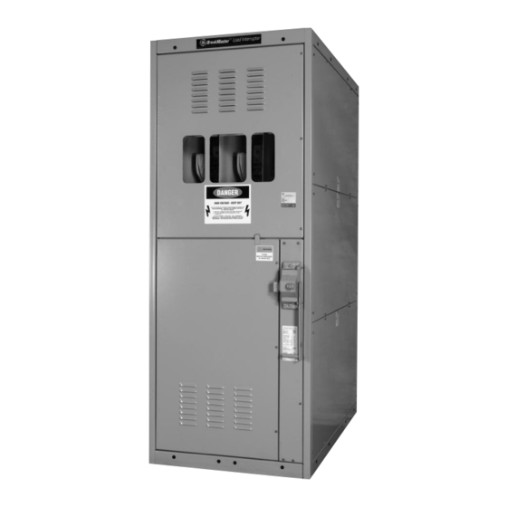
- Page 1 GE Consumer & Industrial Electrical Distribution ™ BreakMaster Load Interrupter Switch Installation and Maintenance imagination at work...
-
Page 2: Table Of Contents
BreakMaster Load Interrupter Switch Overview This instruction book is expressly intended to cover the installation, operation and maintenance of GE’s BreakMaster Load Interrupter Switch. This manual does not cover all possible contingencies, variations and details that may arise during installation, operation or maintenance of this equipment. -
Page 3: Section 1 - Introduction
(see Figure 1). Contained on this nameplate are the GE order number, serial number, drawing number, and switch style number. This information should be given to the GE sales office if a question should arise concerning the switchgear or if renewal parts are required. These numbers allow the factory to completely identify the switchgear. -
Page 4: Safe Practices
BreakMaster Load Interrupter Switch Safe Practices Only qualified electrical workers with training and experience on high voltage circuits should be permitted to work on this equipment. They should be familiar with the work to be performed, the safety equipment required and hazards involved. -
Page 5: Section 2 - Receiving
Handling Removable lifting plates are provided on the top of the BreakMaster structure for insertion of hooks to lift the complete structure. This is the only recommended method of moving the BreakMaster structure. Extreme care should be used not to damage or deform the unit if other moving methods are employed. -
Page 6: Section 3 - Feature Identification
BreakMaster Load Interrupter Switch Section 3 – Feature Identification Front View with Top Door Open Front View with Lower Door Open Louvers – Louvers – Switch Oversize Front and Front and Mechanism Inspection Rear Rear Window Safety Mechanical Interlock Highly Visible... -
Page 7: Section 4 - Installation
In order to gain access to the interior, be sure the switchgear is on a true and level surface. To open a manually operated BreakMaster switch, pull the release button and rotate the handle to the open position. -
Page 8: Bolting Torque Valves
BreakMaster conforms to ANSI standards concerning phasing. Phases are arranged A, B, C, front to rear, top to bottom, and left to right at connection points unless otherwise noted on the drawings. The installer is responsible for maintaining continuity of phasing throughout the system. -
Page 9: Connection To Metal Clad Switchgear Assembly
Metal Clad switchgear. Bolt together using hardware furnished with BreakMaster Load Interrupter Switch. 4.6.2 Outdoor Switchgear a. Position units side by side. Holes in BreakMaster switch side sheet around bus cutout will match holes in metal clad switchgear flange. b. Press weather stripping putty on to flange for weather-tight seal. -
Page 10: Field Taping Of Electrical Connections
4.8.1 Materials a. Filler – insulation putty – GE Part #: 55A213957 b. Insulating tape – black, linerless H.V. EPR tape – GE Part # MMC#130C1 (1”) or MMC#130C2 (2”) 4.8.2 Procedure a. Clean area of dirt and foreign matter per Section 6.0.2 b. - Page 11 BreakMaster Load Interrupter Switch 4.11.1 Switch Alignment and Adjustment Procedure DANGER Make sure that all power sources are deenergized before attempting any maintenance. Figure 5 Step 1: Disconnect Pushrods Remove cotter pins and clevis pins that connect pushrods to operating arms of each pole of switch.
- Page 12 BreakMaster Load Interrupter Switch Figure 8 Check that the jaw casting contact surfaces align with the main blades. If necessary to adjust, loosen the jaw casting mounting bolts, tap on the spade terminal to align, then re-tighten the bolts. See Figure 8.
- Page 13 BreakMaster Load Interrupter Switch Figure 11 Step 4: Hinge Contact Pressure Adjustment Switch Blades 600A Switches Open the switch until the arcing blade just clears the arc chute. Connect a spring scale to the main blades approximately 1 ⁄ ” below the jaw contact.
-
Page 14: Section 5 - Operation
BreakMaster Load Interrupter Switch Section 5 – Operation Mechanical Safety Interlocks The GE BreakMaster switch is equipped with switch interlocks and door interlocks as well as provisions for padlocking in either the open or closed position. DANGER Make sure that all power sources are deenergized before attempting any maintenance. -
Page 15: Switch Operation
Standard schemes are available for locking the switch in the open position or the closed position as well as locking the main door closed. Numerous other schemes are available for special requirements, which can coordinate with upstream or downstream devices supplied by GE or other equip- ment manufacturers. -
Page 16: Fuse Replacement Steps
1. All upstream devices that could energize the fuse should be opened, padlocked, and tagged so that inadvertent closure cannot create a hazard. 2. The BreakMaster switch is opened by rotating the handle downward. 3. Before opening the door look through the viewing window to visually verify that all blades are disengaged from their stationary contacts. -
Page 17: Shunt Trip Operating Guidelines
“typical” operation sequence. The terminal designations for the major components, such as the microswitches, motor, reversing contactor, etc., are standard with GE and should not change. Please compare the standard drawing for the appropriate control voltage with the wiring schematic shipped with the unit. This should be done prior to beginning any work. - Page 18 BreakMaster Load Interrupter Switch Operation (motor operated switch) This drive system consists of: 1. Heavy Duty Universal Gear Motor (M) 2. Full-Wave Bridge Rectifier (RECT) 3. Double-throw Contactor 3-Pole or 4-Pole (89XY) 4. Industrial Solenoid (SOL) 5. Clutch and Spring Mechanism Coupled to the Drive Motor (CL & SP) 6.
- Page 19 BreakMaster Load Interrupter Switch Figure 19 Typical Control Diagram The device numbers used in this diagram are from the American National Institute and descriptions are are follow: Stopping Device Line Switch Closing Relay Opening Relay 89/CL Auxiliary Switch on 89 (Closed when 89 is Open)
- Page 20 BreakMaster Load Interrupter Switch Sequence of Operation (For Exact Wiring and Operation Refer to Drawings Furnished with Equipment) (Typical) Apply the proper control voltage to terminals M1 and M2. CAUTION It is essential that the incoming POSITIVE be connected to the POSITIVE terminal of of the drive controls and the NEGATIVE be connected to the NEGATIVE of the drive system.
- Page 21 If Steps 4 and 5 are properly followed, there should be no need for adjustment under an electric operation. Again, the importance is stressed of properly setting the cams prior to testing in the coupled position with the motor drive assembly. Incorrect setting will cause damage. Please call GE if you have any questions.
-
Page 22: Section 6 - Maintenance
BreakMaster Load Interrupter Switch Inspection and Maintenance: Control Circuit Parts Inspection Item Criteria Inspection Method Corrective Action (if necessary) Closing and opening Smooth and correct Test closing and opening devices including Replace any defective device operation by control power of the switch twice... - Page 23 Examine the surface for cracks or streaked discoloration. When tracking is found, the insulation involved must be replaced. In such a case, contact your local GE sales office for replacement parts. 6.0.6 Bus and Conductor (Switch Blade) Check Inspect the buses and connections carefully every year for evidence of overheating or damage.
-
Page 24: Section 7 - Selector Switch Configuration
Section 7 – Selector Switch Configuration When supplied, a two position non load break selector switch is connected in series with the BreakMaster load break switch. The two switches are key interlocked. To operate the selector switch, the BreakMaster switch must be in the off position. -
Page 25: Section 9 - Auto Transfer Switchgear (Lis-Ats) Configuration
Since the key is retained in its lock when a switch is closed or a door is opened, this requires that both switches must be locked in the open position to unlock either main door, preventing access to energized load side bus or fuses. See GE Zenith Operation and Maintenance Manual #71R-2000A for more information. WARNING Only one key should be available to operating personnel for this interlock scheme. - Page 26 BreakMaster Load Interrupter Switch Sequence of Operation for Controller MX250-LIS See GE Zenith document 71R-2000A for more details When Normal Source voltage or frequency falls below the preset “Fail” values (P) Time Delay to start Emergency Source (W) Time Delay to open Normal Source to ensure voltage and frequency stabilization...
-
Page 27: Section 10 - Troubleshooting
BreakMaster Load Interrupter Switch Section 10 – Troubleshooting Trouble Cause Remedy If the switch is overheated because of excess current, one of two remedies can be adopted: Overload Replace with a switch of rating adequate for the present or future loads, or: Rearrange circuits to remove excess load. -
Page 28: Section 11 - How To Contact Ge
GE RESOLVE can answer any questions you have about any product in the GE Electrical Distribution Engineered Products Catalog, Buylog Catalog, and Control Catalog. There is no charge for calling GE RESOLVE. Access is included with every order, courtesy of GE Electrical Distribution. If you need to contact us, call: 1-888-GE-RESOLVE (1-888-437-3765) 8:00 A.M. - Page 29 Should further information be desired or should particular problems arise which are not covered sufficiently for the purchaser’s purposes, the matter should be referred to GE Company. GE Consumer & Industrial 41 Woodford Avenue, Plainville, CT 06062 www.geelectrical.com...
Need help?
Do you have a question about the BreakMaster and is the answer not in the manual?
Questions and answers