Table of Contents
Advertisement
Digital Energy
Multilin
GE Multilin
215 Anderson Avenue, Markham, Ontario
Canada L6E 1B3
Tel: (905) 294-6222 Fax: (905) 201-2098
Internet:
http://www.GEmultilin.com
*1601-9095-A1*
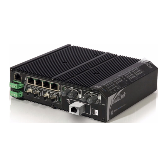
MultiLink ML1200
Managed Field Switch
Instruction Manual
Firmware Revision 3.3x
Manual P/N: 1601-9095-A1
Manual Order Code: GEK-113538
Copyright © 2009 GE Multilin
I I SO9001:2000
GE Multilin's Quality
Management System is
registered to ISO9001:2000
QMI # 005094
UL # A3775
Advertisement
Table of Contents

Related Manuals for GE MultiLink ML1200


Summary of Contents for GE MultiLink ML1200
-
Page 1: Instruction Manual
MultiLink ML1200 Managed Field Switch Instruction Manual Firmware Revision 3.3x Manual P/N: 1601-9095-A1 Manual Order Code: GEK-113538 Copyright © 2009 GE Multilin GE Multilin I I SO9001:2000 215 Anderson Avenue, Markham, Ontario Canada L6E 1B3 Tel: (905) 294-6222 Fax: (905) 201-2098... - Page 2 The contents of this manual are the property of GE Multilin Inc. This documentation is furnished on license and may not be reproduced in whole or in part without the permission of GE Multilin. The content of this manual is for informational use only and is subject to change without notice.
-
Page 3: Table Of Contents
TABLE OF CONTENTS Table of Contents 1: INTRODUCTION GETTING STARTED ..........................1-1 ................ 1-1 NSPECTING THE ACKAGE AND RODUCT ORDER CODES ............................. 1-2 SPECIFICATIONS ..........................1-3 COMMAND LINE INTERFACE FIRMWARE ................. 1-7 ....................... 1-7 ONSOLE ONNECTION ........................1-7 ONSOLE ETUP ......................... - Page 4 TABLE OF CONTENTS ..3-8 LARM ONTACTS FOR MONITORING INTERNAL POWER OFTWARE RAPS ML1200 P (PM) I ..............3-9 ODULE NSTALLATION ONNECTING A ANAGEMENT ONSOLE ERMINAL ML1200 (S -RJ-45 C ) ..3-10 ULTILINK ERIAL ONSOLE 4: OPERATION FUNCTIONALITY ..........................4-1 ....................
- Page 5 TABLE OF CONTENTS ........................6-8 ECURITY ..................... 6-10 UTHORIZED ANAGERS CONFIGURING PORT SECURITY WITH ENERVISTA SOFTWARE ........6-12 ..........................6-12 OMMANDS ............................6-15 ..................... 6-16 UTHORIZED ANAGERS 7: ACCESS USING RADIUS INTRODUCTION TO 802.1X ......................7-1 .......................... 7-1 ESCRIPTION 802.1 .......................
- Page 6 TABLE OF CONTENTS WEB MANAGEMENT SOFTWARE ............10-7 .......................... 10-7 ESCRIPTION CONFIGURING TAG VLANS THROUGH THE COMMAND LINE INTERFACE ....10-12 .......................... 10-12 ESCRIPTION ..........................10-12 OMMANDS ..........................10-13 XAMPLE CONFIGURING TAG VLANS WITH ENERVISTA SECURE WEB MANAGEMENT SOFTWARE ............10-19 .......................... 10-19 ESCRIPTION 11: VLAN REGISTRATION OVERVIEW .............................
- Page 7 TABLE OF CONTENTS .......................... 14-9 ESCRIPTION 15: IGMP OVERVIEW ............................. 15-1 .......................... 15-1 ESCRIPTION IGMP C ........................15-1 ONCEPTS IP M ......................15-4 ULTICAST ILTERS IP M (IGMP) F ....15-5 ESERVED DDRESSES XCLUDED FROM ULTICAST ILTERING IGMP S ........................15-5 UPPORT CONFIGURING IGMP THROUGH THE COMMAND LINE INTERFACE ......
- Page 8 REVISION HISTORY ..........................A-1 ........................A-1 HANGE OTES ....................A-1 HANGES TO THE ANUAL WARRANTY ............................A-2 GE M ................A-2 ULTILIN ARRANTY TATEMENT APPENDIX B: DC POWER SPECIFICATIONS FOR MULTILINK ML1200 SWITCHES, DC POWER INPUT AT 24 V AND –48 V AND 125 V DC POWER INPUT ......B-2 -48 V DC, 24 V DC AND 125 V DC POWER, THEORY OF OPERATION ......
-
Page 9: Getting Started
Remove the items from the shipping container. Be sure to keep the shipping container should you need to re-ship the unit at a later date. To validate the product warranty, please complete and return the enclosed Product Registration Card to GE Multilin as soon as possible. - Page 10 INTRODUCTION CHAPTER 1: INTRODUCTION Order Codes ML1200 ML1200 Module Slot A Slot B Slot C Slot D ML1200 Base Unit Power Supply 250S ML1200 250VDC Chassis 125S ML1200 125VDC Chassis 48VS ML1200 48VDC Chassis 24VS ML1200 24VDC Chassis 12VS ML1200 12VDC Chassis 125D ML1200 125VDC Chassis - Dual Input PSU 48VD...
-
Page 11: Specifications
CHAPTER 1: INTRODUCTION INTRODUCTION Specifications PERFORMANCE Filtering / Forwarding Rate:............... Ethernet(10Mb):14,880 pps Fast Ethernet(100Mb): 148,800 pps Gigabit Ethernet (1000Mb): 1, 488,000 Switching Processing Type: ............... Store and Forward with IEEE 802.3x full-duplex flow -control, non-blocking Data Rate: ....................10Mbps,100Mbps and 1000Mbps Address Table Capacity: .............. - Page 12 INTRODUCTION CHAPTER 1: INTRODUCTION 1000BASE-SX, full-duplex, multi-mode(50μm cable):.... 550m 1000BASE-LX, full-duplex, single-mode(62.5μm cable): ..5Km FIBER MULTI-MODE CONNECTOR TYPES SUPPORTED: Fiber Port, ST-type (twist-lock): ............Fiber multi-mode, 10Mb 10BASE-FL Fiber Port, MTRJ-type (plug-in):............SFF Fiber multi-mode100BASE-FX Fiber Port, SC-type (snap-in): ............Fiber optic multi-mode, 100BASE-FX Fiber Port, ST-type (twist-lock): ............
- Page 13 CHAPTER 1: INTRODUCTION INTRODUCTION POWER CONSUMPTION 35 watts worst case (for a fully loaded fiber model) 12 watts typical (for a small 4 port copper-only model) DUAL DC POWER INPUT (OPTIONAL) A Dual-Source option is available for the 12VDC, 24VDC, – 48VDC, and 125VDC models (not the 250VDC model).
- Page 14 INTRODUCTION CHAPTER 1: INTRODUCTION APPROVALS Applicable Council Directive According to CE Compliance Low voltage directive EN60950-1 EMC Directive EN61000-6-2, EN61000-6-4 North America cULus UL60950-1 C22.2 No. 60950-1 Manufactured under a registered ISO9001 quality program WARRANTY Three years, per UL 60950 temperature rating. Made in USA 1–6 MULTILINK ML1200 MANAGED FIELD SWITCH –...
-
Page 15: Command Line Interface Firmware
CHAPTER 1: INTRODUCTION INTRODUCTION Command Line Interface Firmware 1.4.1 Console Connection The connection to the console is accessed through the DB-9 RS232 connector on the switch marked as the console port. This command line interface (or CLI) provides access to the switch commands. -
Page 16: Console Screen
For additional information on default users, user levels and more, refer to section 1.4.8 - User Management. 1.4.4 Logging In for the First Time For the first time, use the default user name and passwords assigned by GE. They are: • Username: manager Password: manager • Username: operator... -
Page 17: Setting The Ip Parametersu
CHAPTER 1: INTRODUCTION INTRODUCTION If the ML1200 is not connected to a network, then proceed to Step 3 below. or use the Note default IP address. Step 1: The ML1200 will scan the network for a DHCP server. If the server responds, the ML1200 will acquire and set the assigned IP address. - Page 18 INTRODUCTION CHAPTER 1: INTRODUCTION Follow the steps described above for connecting the console cable and setting the console firmware. Power on the switch. Once the login prompt appears, login as manager using default password (manager). Configure the IP address, network mask and default gateway as per the IP addressing scheme for your network.
-
Page 19: Privilege Levels
IP Address: 3.94.247.41 Subnet Mask: 255.255.252.0 Gateway Address: 3.94.244.1 CLI Mode: Manager System Name: ML1200 System Description: 6 Port Modular Ethernet Switch System Contact: multilin.tech@ge.com System Location: Markham, Ontario System ObjectId: 1.3.6.1.4.1.13248.12.7 ML1200# show sysconfig System Name: ML1200 System Contact: multilin.tech@ge.com... -
Page 20: User Management
INTRODUCTION CHAPTER 1: INTRODUCTION 1.4.8 User Management A maximum of five users can be added per switch. Users can be added, deleted or changed from a manager level account. There can be more than one manager account, subject to the maximum number of users on the switch being restricted to five. To add a user, use the command as shown below. -
Page 21: Help
CHAPTER 1: INTRODUCTION INTRODUCTION 1.4.9 Help Typing the command lists the commands you can execute at the current privilege help level. For example, typing at the Operator level shows the following: help ML1200 help > logout ping terminal telnet walkmib Contextless Commands: clear enable... -
Page 22: Exiting
INTRODUCTION CHAPTER 1: INTRODUCTION alarm clear enable exit help logout ping show telnet terminal walkmib whoami ML1200> The following example lists commands starting with a specific string: ML1200> s <TAB> show ML1200> In the following example, the <TAB> key completes the command: ML1200>... -
Page 23: Enervista Secure Web Management
CHAPTER 1: INTRODUCTION INTRODUCTION EnerVista Secure Web Management 1.5.1 Logging in for the First Time Enter the following URL in the web browser to login to the EnerVista Secure Web Management software. https://<IP Address assigned to the switch> Make sure you use HTTPS (secure HTTP) and not HTTP in the URL. Note In the example shown in the previous section, the URL is: https://3.94.247.41... - Page 24 INTRODUCTION CHAPTER 1: INTRODUCTION FIGURE 1–3: Login screen For the first time, Login with the name manager and password manager. Click on Login. After a successful login, the welcome screen is shown. Note the different information provided on the screen and different areas. The menus are used to configure settings on the switch.
-
Page 25: Privilege Levels
CHAPTER 1: INTRODUCTION INTRODUCTION FIGURE 1–4: Welcome screen 1.5.2 Privilege Levels • Operator privilege users: operator privileges allow views of the current configurations but do not allow changes to the configuration. • Manager privilege users: manager privileges allow configuration changes. The changes can be done at the manager prompt or for global configuration as well as specific configuration. - Page 26 INTRODUCTION CHAPTER 1: INTRODUCTION In the following example below, the user peter was added with manager privilege after clicking the add button. 1–18 MULTILINK ML1200 MANAGED FIELD SWITCH – INSTRUCTION MANUAL...
- Page 27 CHAPTER 1: INTRODUCTION INTRODUCTION After successfully adding a user, the added user is displayed in the list of users as shown below. To delete a user, click on the delete icon ( )as shown below. MULTILINK ML1200 MANAGED FIELD SWITCH – INSTRUCTION MANUAL 1–19...
- Page 28 INTRODUCTION CHAPTER 1: INTRODUCTION The firmware will prompt to verify the delete command. To modify the password, view the users as described above and click on the edit icon ( 1–20 MULTILINK ML1200 MANAGED FIELD SWITCH – INSTRUCTION MANUAL...
-
Page 29: Modifying The Privilege Level
CHAPTER 1: INTRODUCTION INTRODUCTION After clicking on the edit icon, the screen opens up for modifying the password. In this example, the user ID peter was selected for modification. The password for peter will be modified after the new password is entered. 1.5.4 Modifying the Privilege Level Privilege levels cannot be changed from the EnerVista Secure Web Management (SWM) -
Page 30: Help
INTRODUCTION CHAPTER 1: INTRODUCTION 1.5.5 Help Help for the EnerVista Secure Web Management software can be obtained by clicking on the Help icon as shown below. 1.5.6 Exiting To exit or logout, click on the logout button. 1–22 MULTILINK ML1200 MANAGED FIELD SWITCH – INSTRUCTION MANUAL... - Page 31 CHAPTER 1: INTRODUCTION INTRODUCTION Confirm the logout by selecting OK in the pop-up window. MULTILINK ML1200 MANAGED FIELD SWITCH – INSTRUCTION MANUAL 1–23...
-
Page 32: Ml1200 Firmware Updates
Multilink ML1200’s Console port, tftp or through ftp. 1.6.2 Selecting the Proper Version The latest version of the firmware is available as a download from the GE Multilin web site. To determine the version of firmware currently installed on your Switch, proceed as follows: Using the EnerVista web interface, log into the Switch using the procedure described earlier. - Page 33 CHAPTER 1: INTRODUCTION INTRODUCTION Save the existing configuration (refer to section 5.4.4 - Saving Configuration for details). Enter the following command: xmodem get type=app ML1200# Do you wish to upgrade the image? [Y or N] Y Please start XModem file transfer now. Refer to “Saving Configuration”...
-
Page 34: Updating Through The Enerv
URL: https://<IP address of the switch> If using FTP, save the configuration before proceeding. GE Multilin recommends a two-step update: first save the configuration to the ftp server, then load the new image and restart the switch (refer to section 5.4.4 - Saving Configuration for details on saving the... - Page 35 After reboot, the firmware is ready for use. If using TFTP, save the configuration before proceeding. GE Multilin recommends a two-step update: • first save the configuration to the TFTP server, • then load the new image and restart the switch (refer to section 5.4.4 - Saving Configuration for details on saving the...
- Page 36 INTRODUCTION CHAPTER 1: INTRODUCTION 1–28 MULTILINK ML1200 MANAGED FIELD SWITCH – INSTRUCTION MANUAL...
-
Page 37: Overview
Secure Web Management, SNMPv2,v3 management, 802.1p QoS Prioritization, Tag-based VLANs, IGMP Snooping and IGMP-L2 multicast management, port security, RADIUS and TACACS+ support, and a choice of redundancy options including RSTP and GE Multilin’s rapid-ring-recovery Ring-Only Mode. Multilink ML1200s are ideal for building a switched, hardened Ethernet network infrastructure, connecting edge devices such as PLCs and IEDs with upstream switches or routers. - Page 38 PRODUCT DESCRIPTION CHAPTER 2: PRODUCT DESCRIPTION points, IP phones) that comply with the IEEE 802.3af PoE standard. The PoE switch ports have an auto-sensing algorithm, so that they provide power only to 802.3af, PoE end devices. PoE is managed by a multi-stage handshake to protect equipment from damage and to manage power budgets .The PoE ports will discontinue supplying power when the PoE powered devices are disconnected.
-
Page 39: Four - Port Sff Fiber Modules
CHAPTER 2: PRODUCT DESCRIPTION PRODUCT DESCRIPTION 2.1.1 Four-port SFF fiber modules (CC Module, CD Module), 100Mb fiber In a four-port SFF (Small Form Factor) fiber port module, all of the fiber ports are of the same speed (100Mb), mode, and connector type. Small Form Factor (SFF) Fiber Ports come in multi-mode forms MT-RJ or LC-type connectors, and single-mode form LC-type connectors. -
Page 40: Four -Port Copper Module
PRODUCT DESCRIPTION CHAPTER 2: PRODUCT DESCRIPTION 2.1.2 Four-Port Copper Module, C1 Module MDIX) The ML1200’s 4-port Copper module, the C1 Module, provides four 10/100Mb switched RJ- 45 ports. The 10/100Mb switched ports normally (as a default setting) are independently N- way auto-negotiating and auto-crossover (MDIX) for operation at 10 or 100Mb speed in full- or half-duplex mode. -
Page 41: Two -Port Fiber Modules
CHAPTER 2: PRODUCT DESCRIPTION PRODUCT DESCRIPTION The LEDs on C2 PoE modules are slightly different compared to regular (non-PoE) RJ-45 modules as shown in the figure below. When the PoE port is in use, the PoE LED is ON when connected properly to an 803.af compliant PD device on that port. -
Page 42: Sfp Gigabit (1000M Bps )
PRODUCT DESCRIPTION CHAPTER 2: PRODUCT DESCRIPTION 2.1.6 SFP Gigabit (1000Mbps) port modules The Gigabit port options for the modular slot come in a few different configurations of Fiber SFP’s or RJ-45’s. The Multilink ML1200 offers only SFPs (Small Form Pluggable) for Gigabit speed. -
Page 43: Frame Buffering And Flowc
CHAPTER 2: PRODUCT DESCRIPTION PRODUCT DESCRIPTION 2.1.8 Frame Buffering and Flow Control Multilink ML1200’s are store-and-forward switches. Each frame (or packet) is loaded into the Switch’s memory and inspected before forwarding can occur. This technique ensures that all forwarded frames are of a valid length and have the correct CRC, i.e., are good packets. - Page 44 PRODUCT DESCRIPTION CHAPTER 2: PRODUCT DESCRIPTION Features and Benefits • Managed switching for high performance Ethernet LANs. Multilink ML1200 Switches provide unicast non-blocking (all ports can run at full speed at once) performance with standard Managed Network Software included. They are typically used in LAN traffic centers with up to 12 100Mb +2 Gigabit ports for backbone connections, where managed network services are desired.
- Page 45 CHAPTER 2: PRODUCT DESCRIPTION PRODUCT DESCRIPTION QoS, Port- and tag-based VLANs, GVRP, IGMP Snooping, SNMPc GUI support; Event Log; SNTP client for time-of-day; BootP and DHCP client for IP configuring, and password security and Secured Web interface. MULTILINK ML1200 MANAGED FIELD SWITCH – INSTRUCTION MANUAL 2–9...
-
Page 46: Applications
PRODUCT DESCRIPTION CHAPTER 2: PRODUCT DESCRIPTION Applications Multilink ML1200 Field Switches offer high performance, modularity and availability. They provide the flexibility of 100Mbps fiber and copper ports as well as single or dual Gigabit (1000Mb) ports, with industry-standard LAN management software. Multilink ML1200 Switches are easily used in a variety of applications including client/server computing, secure VLAN- performance upgrades to departmental networks, and stream traffic for VOIP and audio/video applications. - Page 47 CHAPTER 2: PRODUCT DESCRIPTION PRODUCT DESCRIPTION Extended temperature ratings and a variety of options for AC/DC power supplies qualify this managed ML1200 switch for use in non-temperature controlled networks and many other temperature sensitive critical Industrial applications where above normal room temperatures occur while the network is in operation.
- Page 48 PRODUCT DESCRIPTION CHAPTER 2: PRODUCT DESCRIPTION The ML1200 Managed Fiber with the Ring-Only Mode feature easily fulfill the redundant requirement with a secure and fast reconfiguration time for cable breakup when set up in a ring topology. The Gigabit port option boosts the bandwidth for high speed to support the peak traffic and minimize congestion.
-
Page 49: Preparation
Digital Energy Multilin Multilink ML1200 Managed Field Switch Chapter 3: Installation Installation Preparation Before installing the equipment, it is necessary to take the following precautions: If the equipment is mounted in an enclosed or multiple rack assembly, the steady-state long-term environmental temperature around the equipment must be less than or equal to 60 If the equipment is mounted in an enclosed or multiple rack assembly, adequate airflow must be maintained for proper and safe operation. -
Page 50: Connecting Ethernet Media
INSTALLATION CHAPTER 3: INSTALLATION Connecting Ethernet Media The Multilink ML1200 Switches are specifically designed to support all standard Ethernet media types within a single Switch unit. This is accomplished by using a family of different Fiber Connectors which can be individually selected and configured per-slot. See Section 2.2 for a description of the PMs. - Page 51 Use the LINK LED to ensure proper connectivity by noting that the LED will be illuminated when the unit is powered and proper connection is established For Power Substations: In support of the IEEE 1613 Class 2 standard, GE Multilin advises Note...
- Page 52 Crossover RJ-45 (4-twisted pair) category 5 or higher cabling. The maximum length supported on copper 1000BASE-T is 100mts (328 ft.). The various SFPs transceivers supported by the GE Multilin ML1200’s C slot are: 3–4 MULTILINK ML1200 MANAGED FIELD SWITCH – INSTRUCTION MANUAL...
- Page 53 CHAPTER 3: INSTALLATION INSTALLATION Module Model# Gigabit Gb Modules, fixed ports--SFP H1 - H6 Module 2 SFP H7 Module 2 CU H8 - HD Module 1SFP, 1CU HE - HJ Module 1 SFP HK Module 1 CU 3.2.0.7 Connecting Fiber Optic Cable to SFP Transceivers Before connecting the fiber optic cable, remove the protective dust caps from the tips of the connectors on the PM.
-
Page 54: Din-Rail Mounting Them
INSTALLATION CHAPTER 3: INSTALLATION Mechanical Installation 3.3.1 DIN-Rail Mounting the Multilink ML1200 The Multilink ML1200 is designed for use in a “factory floor” industrial environment. It is available with optional DIN-Rail brackets to mount it securely in a metal factory floor enclosure, maintained vertically for proper convection cooling of the unit. - Page 55 CHAPTER 3: INSTALLATION INSTALLATION For best cooling of the ML1200, attach the metal brackets to metal (rather than wood or plastic). Attaching to metal helps conduct heat away from the ML1200 through the metal brackets and into the metal support structure. Since the ML1200 has special internal thermal techniques (patent pending) to move the heat generated by the electronic components inside into the case, the case may be quite warm to the touch during normal operation.
-
Page 56: Onfiguration
INSTALLATION CHAPTER 3: INSTALLATION Electrical Installation 3.4.1 Powering the Multilink ML1200 Managed Field Switch The DC internal power supply supports installation environments where the DC voltage is from 18 to 150 volts depending on the model selected. The power consumption will range from about 20 up to 35 watts, depending on the port quantity and types in the configuration.. -
Page 57: Ml1200 Port Module (Pm) Installation
CHAPTER 3: INSTALLATION INSTALLATION The Alarm Contacts are on the front left area (next to the DC power source) of the Multilink ML1200 unit and are green in color as shown in the picture. 3.4.3 ML1200 Port Module (PM) Installation Multilink ML1200 Switches are normally received from the factory with all required Port Modules installed. -
Page 58: Connecting A Management Console Terminal To Multilink Ml1200 (Serial -Rj-45 Console Port )
RJ-45 for the ML1200 side and a USB cable connector option on the other end (e.g computer). For Power Substations: In support of the IEEE 1613 Class 2 standard, GE Multilin advises Note that, for substation applications, the serial RJ-45console ports are intended for temporary connectivity to other equipment such as PCs. -
Page 59: Switching Functionality
Digital Energy Multilin Multilink ML1200 Managed Field Switch Chapter 4: Operation Operation This chapter describes the functions and operation of the Multilink ML1200 Switch. Functionality 4.1.1 Switching Functionality A Multilink ML1200 provides switched connectivity at Ethernet wire-speed among all of its ports. -
Page 60: Status Leds
OPERATION CHAPTER 4: OPERATION 4.1.1.2 Address Learning All Multilink ML1200 units have address table capacities of 4K node addresses suitable for use in larger networks. They are self-learning, so as nodes are added, removed or moved from one segment to another, the ML1200 Switch automatically keeps up with node locations. -
Page 61: F Low - Control , Ieee
CHAPTER 4: OPERATION OPERATION The auto-negotiation logic will attempt to operate in descending order and will normally arrive at the highest order mode that both devices can support at that time. (Since auto- negotiation is potentially an externally controlled process, the original “highest order mode”... -
Page 62: Power Budget Calculations For Ml1200 Pm's With Fiber Media
OPERATION CHAPTER 4: OPERATION 4.1.5 Power Budget Calculations for ML1200 PM’s with Fiber Media Receiver Sensitivity and Transmitter Power are the parameters necessary to compute the power budget. To calculate the power budget of different fiber media installations using Multilink products, the following equations should be used: OPB (Optical Power Budget) = P (min) - P (min) - Page 63 CHAPTER 4: OPERATION OPERATION H4, HH 1000 Mb FX Single-Mode 25 1310 9/125 -3.0 (Gigabit) H5, HI 1000 Mb FX Single-Mode 40 1550 9/125 -5.0 (Gigabit) H6, HJ 1000 Mb FX Single-Mode 70 1550 9/125 -2.0 (Gigabit) * The use of either multi-mode or single-mode fiber to operate at 100Mbps speed over Note long distances (i.e., in excess of approx.
-
Page 64: Multilink Ml1200 Managed Field Switch Port Modules
OPERATION CHAPTER 4: OPERATION Multilink ML1200 Managed Field Switch Port Modules This chapter describes each Port Module (PM), including appearance, functionality, and status displays. 4.2.1 Inspecting the Package and Product This section applies only to Port Modules shipped as separate items, i.e., ML1200 PMs that are not factory installed. - Page 65 CHAPTER 4: OPERATION OPERATION Multilink ML1200 Managed Switch, the copper port supports the standard distance 100m on each port and the fiber port supports fiber optic cable distances up the IEEE-standard 100Mbps distance limits, i.e., typically 2km at full-duplex and 412m at half-duplex. Each port has an Activity (ACT) LED indicating packets being received.
- Page 66 OPERATION CHAPTER 4: OPERATION 4.2.2.4 CB Module, 2 Ports @100Mbps single-mode FX-SC-type, Sgl.M The CB Module is also a Fiber module equipped with 2 Single-mode (Long Reach) SC-type connectors. It provides a long reach Fiber function in one module to the ML1200 Switches, supporting 100Mb single-mode (Long-Reach) fiber network segments.
- Page 67 CHAPTER 4: OPERATION OPERATION Each port has an Activity (ACT) LED indicating packets being received, a Link (LK) LED that indicates proper connectivity with the remote device when lit, and a FDX/HDX LED to indicate full-duplex mode when lit (or half-duplex when off). The 10/100 LED indicates 100Mbps speed when lit and at 10Mbps speed when off.
- Page 68 OPERATION CHAPTER 4: OPERATION The cable end is a “plug-in” connector with both fiber strands terminated in one housing that cannot be improperly inserted. Each port has an Activity (ACT) LED indicating packets being received, a Link (LK) LED indicating proper connectivity with the remote device when lit, and a FDX/HDX LED indicating full-duplex mode when lit (or half-duplex when off).
- Page 69 RJ-45 ports to automatically Link with any RJ-45 device and eliminate the use of cross-over cable. For Power Substations: In support of the IEEE 1613 Class 2 standard, GE Multilin advises Note that, for substation applications, the RJ-45 ports are intended for connectivity to other communication equipment such as routers or telecommunication multiplexers installed in close proximity (i.e., less than 2 meters or 6.5ft) to the ML1200.
- Page 70 OPERATION CHAPTER 4: OPERATION • In the case where the 48VDC power in not internally connected and no power is coming to the PoE ports for some reason, all the PoE port LEDs are ON simultaneously to indicate a trouble condition. The ports will still operate properly for data traffic.
-
Page 71: Before Calling For Assistance
CHAPTER 4: OPERATION OPERATION described in this section or if the Multilink ML1200 Switch is not performing as expected, do not attempt to repair the unit; instead contact your supplier for assistance or contact GE Multilin Customer Support. 4.2.3 Before Calling for Assistance If difficulty is encountered when installing or operating the unit, refer back to the Installation Section of the applicable chapter of this manual. - Page 72 OPERATION CHAPTER 4: OPERATION 4–14 MULTILINK ML1200 MANAGED FIELD SWITCH – INSTRUCTION MANUAL...
-
Page 73: Overview
Digital Energy Multilin Multilink ML1200 Managed Field Switch Chapter 5: IP Addressing IP Addressing IP Address and System Information 5.1.1 Overview It is assumed that the user has familiarity with IP addresses, classes of IP addresses and related netmask schemas (for example, class A, B, and C addressing). Without an IP address, the switch operates as a standalone Layer 2 switch. - Page 74 IP ADDRESSING CHAPTER 5: IP ADDRESSING Edit the IP address information. Besides manually assigning IP addresses, there are other means to assign an IP address automatically. The two most common procedures are using DHCP and bootp. 5–2 MULTILINK ML1200 MANAGED FIELD SWITCH – INSTRUCTION MANUAL...
-
Page 75: Importance Of An Ip Address
CHAPTER 5: IP ADDRESSING IP ADDRESSING Importance of an IP Address 5.2.1 DHCP and bootp DHCP is commonly used for setting up addresses for computers, users and other user devices on the network. bootp is the older cousin of DHCP and is used for setting up IP addresses of networking devices such as switches, routers, VoIP phones and more. - Page 76 IP ADDRESSING CHAPTER 5: IP ADDRESSING argument is only valid with the type. This option allows the switch to bootimg bootp load the image file from the bootp server. This is useful when a new switch is placed on a network and the IT policies are set to load a specific image which is supported and tested by IT personnel.
-
Page 77: Using Telnet
CHAPTER 5: IP ADDRESSING IP ADDRESSING After the changes are completed for each section, click OK to register the changes. Note that if the IP address is changed, the session has to be restarted with the new IP http address. 5.2.4 Using Telnet The telnet client is enabled on the ML1200. - Page 78 IP ADDRESSING CHAPTER 5: IP ADDRESSING command can show the status of the telnet client as well as other show console console parameters. The following example reviews the console parameters with the show command. Note that telnet is enabled. console ML1200# show console Console/Serial Link...
- Page 79 CHAPTER 5: IP ADDRESSING IP ADDRESSING For example: user ML1200# useraccess user=peter service=telnet enable ML1200(user)## Telnet Access Enabled. exit ML1200(user)## show session ML1200# Current Sessions: SL# Sessn Id Connection User Name User Mode 163.10.10.14 manager Manager 163.11.11.1 peter Manager 163.12.12.16 operator Operator kill session id=3...
-
Page 80: Setting Parameters
IP Address: 3.94.247.41 Subnet Mask: 255.255.252.0 Gateway Address: 3.94.244.1 CLI Mode: Manager System Name: ML1200 System Description: 12 Port Modular Ethernet Switch System Contact: multilin.tech@ge.com System Location: Markham, Ontario System ObjectId: 1.3.6.1.4.1.13248.12.7 ML1200# The following example lists system parameters using the command. -
Page 81: Date And Time
System UpTime: 7 Days 12 Hours 30 Mins 46 Secs ML1200# System variables can be changed. Below is a list of system variables which GE recommends changing. • : Using a unique name helps you to identify individual devices in a System Name network. -
Page 82: Network Time
IP ADDRESSING CHAPTER 5: IP ADDRESSING To set the time to be 08:10 am in the -5 hours from GMT (Eastern Standard Time) and to set the date as 11 May 2005, the following sequence of commands are used. ML1200# set time hour=8 min=10 sec=0 zone=GMT-5:00 Success in setting device time ML1200#... - Page 83 CHAPTER 5: IP ADDRESSING IP ADDRESSING To set the SNTP server to be 3.94.210.5 (with a time out of 3 seconds and a number of retries set to 3 times); allowing the synchronization to be ever 5 hours, the following sequence of commands are used ML1200# sntp...
- Page 84 IP ADDRESSING CHAPTER 5: IP ADDRESSING After the proper SNTP values are entered, click OK to register the changes, or click Cancel to back out from the changes made. To add an SNTP server, click the add button on the Configuration > SNTP menu. The menu prompts you to add IP address of an SNTP server, the time out in seconds and the number of retries, before the time synchronization effort is aborted.
- Page 85 CHAPTER 5: IP ADDRESSING IP ADDRESSING The Time Out value is in seconds. Note the time server can be a NTP server available on the Internet. Ensure the IP parameters are configured for the switch and the device can be pinged by the switch.
-
Page 86: System Configuration
IP ADDRESSING CHAPTER 5: IP ADDRESSING System Configuration 5.4.1 Saving and Loading – Command Line Place the Switch offline while transferring Setting Files to the Switch. Note When transferring Settings Files from one Switch to another, the IP address of the originating Switch will also be transferred. - Page 87 # test environment prior to use in a "live" production network. # All modifications are made at the User's own risk and are # subject to the limitations of the GE MultiLink software End User # License Agreement (EULA). Incorrect usage may result in # network shutdown.
- Page 88 CRC computed and stored in the file would not be matched. Should you want to edit, edit the System portion of the file only. GE Multilin, Inc. recommends editing the “script” file (see below) File names cannot have special characters such as *#!@$^&* space and control...
-
Page 89: Displaying Configuration
CHAPTER 5: IP ADDRESSING IP ADDRESSING 5.4.3 Displaying configuration Using SWM, the need to display specific CLI commands for configuring capabilities is not needed. The menus are modular and are alphabetically sorted to display each necessary component in a logical manner. This section is repeated from the CLI manual, should the need arise to view the necessary commands. - Page 90 IP ADDRESSING CHAPTER 5: IP ADDRESSING # System Manager - This area configures System related information. ########################################################## [SYSTEM] ***Edit below this line only**** system_name=Main system_contact=someone@joe.com system_location= Markham, Ontario boot_mode=manual system_ip=192.168.1.15 system_subnet=0.0.0.0 system_gateway=192.168.1.11 idle_timeout=10 telnet_access=enable snmp_access=enable web_access=enable --more— FIGURE 5–2: ’show config’ command output 5–18 MULTILINK ML1200 MANAGED FIELD SWITCH –...
- Page 91 CHAPTER 5: IP ADDRESSING IP ADDRESSING ML1200# show config module=snmp [HARDWARE] type= ML1200 slotB=8 Port TP Module ########################################################## # Network Management - This area configures the SNMPv3 agent. ########################################################## [SNMP] engineid=LE_v3Engine defreadcomm=public defwritecomm=private deftrapcomm=public authtrap=disable com2sec_count=0 group_count=0 view_count=1 view1_name=all view1_type=included view1_subtree=.1 view1_mask=ff --more—...
-
Page 92: Saving Configuration
IP ADDRESSING CHAPTER 5: IP ADDRESSING ML1200# show config module=snmp,system [HARDWARE] type= ML1200 slotB=8 Port TP Module ########################################################## # System Manager - This area configures System related information. ########################################################## [SYSTEM] ***Edit below this line only**** system_name=Main system_contact=someone@joe.com system_location= Markham, Ontario boot_mode=manual system_ip=192.168.1.15 system_subnet=0.0.0.0... - Page 93 With release 1.7 and higher, the configuration can be saved in the older format (binary Note object) or in a new format as an ASCII file. The new format is recommended by GE Multilin. Use the old format only if there are multiple MultiLink switches on the network running different versions of software.
-
Page 94: Script File
The script file does not have a check sum at the end and is used for configuring a large number of switches easily. As with any configuration file that is uploaded, GE Multilin, Inc. recommends that modifications of this file and the commands should be verified by the user in a test environment prior to use in a "live"... -
Page 95: Saving And Loading - Enervista Software
In the above example, note that all the commands are CLI commands. This script provides an insight into the configuration of GE MultiLink switches settings. GE Multilin, Inc. recommends that modifications of this file and the commands should be verified by the User in a test environment prior to use in a "live"... - Page 96 IP ADDRESSING CHAPTER 5: IP ADDRESSING This process can also be used to update new software to the managed MultiLink switches. Before the software is updated, it is advised to save the configurations. Reloading of the configuration is not usually necessary, but in certain situations it may be needed, and it is recommended that you save configurations before a software update.
-
Page 97: Host Names
CHAPTER 5: IP ADDRESSING IP ADDRESSING If the changes need to be ignored, click on Cancel and reboot the switch. If the changes need to be saved, click on OK. The following figures illustrate saving changes made after adding an SNTP server. This is done by clicking on the Save icon to save current configuration 5.4.7 Host Names... - Page 98 IP ADDRESSING CHAPTER 5: IP ADDRESSING To add a host, click the Add button. Fill in all the fields below to create the necessary host entries. 5–26 MULTILINK ML1200 MANAGED FIELD SWITCH – INSTRUCTION MANUAL...
-
Page 99: Erasing Configuration
CHAPTER 5: IP ADDRESSING IP ADDRESSING To delete or edit the entries, use the delete or edit icons next to each entry shown above. 5.4.8 Erasing Configuration Kill Config option using SWM To erase the configuration and reset the configurations to factory defaults, you can use the kill config option from Administration tab by selecting kill config. - Page 100 IP ADDRESSING CHAPTER 5: IP ADDRESSING In the example below “system” module box has been checked. In this case after kill Config command is issued by pressing the OK button, the Switch will perform a factory dump restoring all the Switch settings back to factory defaults except for the “System” settings which will be retained.
- Page 101 CHAPTER 5: IP ADDRESSING IP ADDRESSING Here is a list of the modules and related settings that can be selected not to default back to factory default settings. Name Areas affected System IP Configuration, Boot mode User Users settings (e.g. login names, passwords) Port settings, Broadcast Protection and QoS Port settings...
- Page 102 IP ADDRESSING CHAPTER 5: IP ADDRESSING It is recommended to save the configuration (using saveconf command discussed above) before using the kill config command. The following two examples illustrate how to erase all the Switch’s configuration using the kill config command and the second example illustrates how to erase all the Switch’s configuration with the exception of ‘system’...
-
Page 103: Ipv6
CHAPTER 5: IP ADDRESSING IP ADDRESSING IPv6 This section explains how to access the GE MultiLink switches using IPv6 instead of IPv4 addressing. IPv6 provides a much larger address space and its use is often required. Assumptions It is assumed here that the user is familiar with IP addressing schemes and has other supplemental material on IPv6, configuration, routing, setup and other items related to IPv6. -
Page 104: Ipv6 Addressing
IP ADDRESSING CHAPTER 5: IP ADDRESSING addresses. The scalability of multicast routing is improved by adding a "scope" field to multicast addresses. • A new type of address called an "anycast address" is defined, that identifies sets of nodes where a packet sent to an anycast address is delivered to one of these nodes. -
Page 105: Configuring Ipv6
CHAPTER 5: IP ADDRESSING IP ADDRESSING Details of the addressing are covered by numerous articles on the WWW as well as other literature, and are not covered here. 5.5.4 Configuring IPv6 The commands used for IPv6 are the same as those used for IPv4. Some of the commands will be discussed in more details later. -
Page 106: List Of Commands In This Chapter
IP ADDRESSING CHAPTER 5: IP ADDRESSING Syntax telnet <IPv6 address> - telnet to an IPv6 station Example – telnet fe80::220:6ff:fe25:ed80 Besides, if the end station supports IPv6 addressing (as most Linux and Windows systems do), one can access the switch using the IPv6 addressing as shown in the example below http://fe80::220:6ff:fe25:ed80 5.5.5 List of commands in this chapter... -
Page 107: Securing Access
Digital Energy Multilin Multilink ML1200 Managed Field Switch Chapter 6: Access Considerations Access Considerations Securing Access 6.1.1 Description This section explains how the access to the MultiLink ML1200 Managed Field Switch can be secured. Further security considerations are also covered such as securing access by IP address or MAC address. -
Page 108: Port Security Feature
ACCESS CONSIDERATIONS CHAPTER 6: ACCESS CONSIDERATIONS 6.1.3 Port Security Feature The port security feature can be used to block computers from accessing the network by requiring the port to validate the MAC address against a known list of MAC addresses. This port security feature is provided on an Ethernet, or Fast Ethernet, port. -
Page 109: Configuring Port Security Through The Command Line Interface
CHAPTER 6: ACCESS CONSIDERATIONS ACCESS CONSIDERATIONS Configuring Port Security through the Command Line Interface 6.2.1 Commands To configure port security, login as a level 2 user or as a manager. Once logged in, get to the port-security configuration level to setup and configure port security with the following command syntax: configure port-security port-security... -
Page 110: Allowing Mac Addresses
ACCESS CONSIDERATIONS CHAPTER 6: ACCESS CONSIDERATIONS • - removes specific or all MAC addresses from port security lookup remove mac • - observe list of specified ports and notify if signal port=<num|list|range> there is a security breach on the list of port specified. The signal can be a log entry, a trap to the trap receiver specified as part of the SNMP commands (where is that specified) or both There is a limitation of 200 MAC addresses per port and 500 MAC addresses per switch for... - Page 111 CHAPTER 6: ACCESS CONSIDERATIONS ACCESS CONSIDERATIONS To deny a mac address, use the following: #port-security (port-security)##ps enable (port-security)##deny mac=<address,list,range> port=<num,list,range> (port-security)##action port=<num,list,range>drop Example 6-1 views port security settings on a switch. Learning is enabled on port 1. This port has 6 stations connected to it with the MAC addresses as shown. Other ports have learning disabled and the MAC addresses are not configured on those ports.
- Page 112 ACCESS CONSIDERATIONS CHAPTER 6: ACCESS CONSIDERATIONS Example 6-2 shows how to enable learning on a port. After the learning is enabled, the port security can be queried to find the status of MAC addresses learnt. If there were machines connected to this port, the MAC address would be shown on port 3 as they are shown on port 1.
- Page 113 CHAPTER 6: ACCESS CONSIDERATIONS ACCESS CONSIDERATIONS Disable learning on required ports (for example, use the learn command). port=3,5 disable (Optional step) Add any specific MAC addresses, if needed, to allow designated devices to access the network (use the command). mac=00:c1:00:7f:ec:00 port=3,5 Disable access to the network for unauthorized devices (Use action depending on whether the port should...
-
Page 114: Security Logs
ACCESS CONSIDERATIONS CHAPTER 6: ACCESS CONSIDERATIONS Example 6-5 illustrates these steps for setting up port security on a specific port: Once port security is setup, it is important to manage the log and review the log often. If the signals are sent to the trap receiver, the traps should also be reviewed for intrusion and other infractions. - Page 115 CHAPTER 6: ACCESS CONSIDERATIONS ACCESS CONSIDERATIONS (such as unexpected behavior). The specific types of logs can be viewed and cleared. The command displays the log information and the command clears show log clear log the log entries. The syntax for these commands is shown below: show log [1..5|informational|debug|fatal |critical|activity] clear log [informational|debug|activity |critical|fatal] command set the number of lines to be collected in the log before the...
-
Page 116: Authorized Managers
(information, severity level 1) indicates routine events. • (activity, severity level 2) indicates the activity on the switch. • (debug, severity level 3) is reserved for GE Multilin internal diagnostic information • (critical, severity level 4) indicates that a severe switch error has occurred. •... - Page 117 CHAPTER 6: ACCESS CONSIDERATIONS ACCESS CONSIDERATIONS It is assumed here that the user is familiar with IP addressing schemes (e.g. class A, B, C, Note etc.), subnet masking and masking issues such as how many stations are allowed for a given subnet mask.
-
Page 118: Configuring Port Security With Enervista Software
ACCESS CONSIDERATIONS CHAPTER 6: ACCESS CONSIDERATIONS Configuring Port Security with EnerVista Software 6.3.1 Commands After enabling the EnerVista Secure Web Management software, Select the Configuration > Port > Security menu item to configure port security as shown below. From the menu shown above, each individual port can be configured for the proper action on the port, auto learn MAC addresses and specify individual MAC addresses. - Page 119 CHAPTER 6: ACCESS CONSIDERATIONS ACCESS CONSIDERATIONS Note that the screen also provides an overview of each port on the switch. Each port can be individually configured for the proper port security action. Each individual port can be configured by clicking on the edit icon ( ).
- Page 120 ACCESS CONSIDERATIONS CHAPTER 6: ACCESS CONSIDERATIONS There is a limitation of 200 MAC addresses per port and 500 MAC addresses per switch for port security. After clicking on the Add button, the following screen appears, allowing the entry of a specific MAC address Once port security is setup, it is important to manage the log and review it often.
-
Page 121: Logs
CHAPTER 6: ACCESS CONSIDERATIONS ACCESS CONSIDERATIONS 6.3.2 Logs All events occurring on the Managed MultiLink ML1200 Managed Field Switch are logged. The events can be informational (e.g. login, STP synchronization etc.), debugging logs (for debugging network and other values), critical (critical events), activity (traffic activity) and fatal events (such as unexpected behavior). -
Page 122: Authorized Managers
(information, severity level 1) indicates routine events. • (activity, severity level 2) indicates the activity on the switch. • (debug, severity level 3) is reserved for GE Multilin internal diagnostic information • (critical, severity level 4) indicates that a severe switch error has occurred. •... - Page 123 CHAPTER 6: ACCESS CONSIDERATIONS ACCESS CONSIDERATIONS In the following example, any computer on 10.10.10.0 sub network is allowed (note how the subnet mask is used to indicate that). Also, a specific station with IP address 192.168.15.25 is allowed (again note how the subnet mask is used to allow only one specific station in the network) and an older station with IP address 192.168.15.15 is removed.
- Page 124 ACCESS CONSIDERATIONS CHAPTER 6: ACCESS CONSIDERATIONS 6–18 MULTILINK ML1200 MANAGED FIELD SWITCH – INSTRUCTION MANUAL...
-
Page 125: Introduction To 802.1X
Digital Energy Multilin Multilink ML1200 Managed Field Switch Chapter 7: Access Using RADIUS Access Using RADIUS Introduction to 802.1x 7.1.1 Description The TACACS+ protocol is the latest generation of TACACS. TACACS is a simple UDP (User Datagram Protocol) based access control protocol originally developed by BBN for the MILNET (Military Network). - Page 126 ACCESS USING RADIUS CHAPTER 7: ACCESS USING RADIUS access to services that are accessible via that port. The authenticator is responsible for communication with the supplicant and for submitting the information received from the supplicant to a suitable authentication server. This allows the verification of user credentials to determine the consequent port authorization state.
- Page 127 CHAPTER 7: ACCESS USING RADIUS ACCESS USING RADIUS 10. If the supplicant does not have the necessary credentials, a RADIUS-Access- Deny packet is relayed to the supplicant as an EAP-Failure frame. The access to the network continues to be blocked. FIGURE 7–2: 802.1x authentication details The ML1200 software implements the 802.1x authenticator.
-
Page 128: Configuring 802.1X Through The Command Line Interface
ACCESS USING RADIUS CHAPTER 7: ACCESS USING RADIUS Configuring 802.1x through the Command Line Interface 7.2.1 Commands On enabling 802.1x ports, make sure the port which connects to the RADIUS servers needs to be manually authenticated. To authenticate the port, use the command. - Page 129 CHAPTER 7: ACCESS USING RADIUS ACCESS USING RADIUS and integer values can range from 0 to 10. The argument is optional and transmit represents the transmit period. This is the time in seconds the authenticator waits to transmit another request for identification from the supplicant. The default value is 30 and values range from 1 to 65535 seconds command determines how the authenticator (MultiLink ML1200 Managed reauth...
-
Page 130: Example
ACCESS USING RADIUS CHAPTER 7: ACCESS USING RADIUS 7.2.2 Example Example 7-1 demonstrates how to secure the network using port access. Ensure there is no 802.1x or RADIUS server defined. Only one RADIUS server can be defined for the entire network. - Page 131 CHAPTER 7: ACCESS USING RADIUS ACCESS USING RADIUS Setting port control parameters (continued) ML1200(auth)## backend port=2 supptimeout=45 servertimeout=60 maxreq=5 Successfully set backend server authentication This command sets timeout parameter(s) characteristics and the number of ML1200(auth)## show-port backend requests before access is denied. Port Supp Timeout Server Timeout...
- Page 132 ACCESS USING RADIUS CHAPTER 7: ACCESS USING RADIUS Setting port control parameters (continued) ML1200(auth)## reauth port=1 status=enable period=300 This command forces the Successfully set re-authentication parameter(s) authentication period on port #1 every 5 minutes; all other ports are ML1200(auth)## shoW-port reauth force authenticated every hour as Port Reauth Status...
-
Page 133: Commands
CHAPTER 7: ACCESS USING RADIUS ACCESS USING RADIUS Configuring 802.1x with EnerVista Secure Web Management software 7.3.1 Commands To access the 802.1x configuration window, select the Configuration > Radius > Server menu item. First, select the server. Do not enable RADIUS capabilities until you have ensured that the ports are configured properly. - Page 134 ACCESS USING RADIUS CHAPTER 7: ACCESS USING RADIUS The following figure illustrates the editing of information for the RADIUS server. Note the UDP port number can be left blank and the default port 1812 is used. After configuring the server information, specific port information is configured. Select the Configuration >...
- Page 135 CHAPTER 7: ACCESS USING RADIUS ACCESS USING RADIUS Ensure that the port which has the RADIUS server is force authorized and asserted. For other ports (user ports), it is best to leave the Control on auto and Initialize on de-asserted. To change the port access characteristics when authenticating with a RADIUS server, Select the Configuration >...
- Page 136 ACCESS USING RADIUS CHAPTER 7: ACCESS USING RADIUS The Max Reauth column shows the permitted reauthentication attempts before the port becomes unauthorized. Values are integers ranging from 0 to 10, with a default of 2. The Tx Period column represents the transmit period. This is the time (in seconds) the authenticator waits to transmit another request for identification from the supplicant.
- Page 137 CHAPTER 7: ACCESS USING RADIUS ACCESS USING RADIUS The port authentication characteristics define how the authenticator (ML1200 switch) does the re-authentication with the supplicant or PC. These are defined through the Configuration > Radius > Port > Access > Reauth menu item. The Reauth Period represents the time the authenticator waits before a re-authentication process will be done again to the supplicant.
- Page 138 ACCESS USING RADIUS CHAPTER 7: ACCESS USING RADIUS After all the port characteristics are enabled, Do not forget to save the configuration using the save ( ) icon and enabling RADIUS from the Configuration > Radius > Server menu. 7–14 MULTILINK ML1200 MANAGED FIELD SWITCH –...
-
Page 139: Introduction To Tacacs
Digital Energy Multilin Multilink ML1200 Managed Field Switch Chapter 8: Access using TACACS+ Access using TACACS+ Introduction to TACACS+ 8.1.1 Overview The TACACS+ protocol (short for Terminal Access Controller Access Control System) provides access control for routers, network access servers and other networked computing devices via one or more centralized servers. -
Page 140: Tacacs+ Flow
ACCESS USING TACACS+ CHAPTER 8: ACCESS USING TACACS+ 8.1.2 TACACS+ Flow TACACS works in conjunction with the local user list on the ML1200 software (operating system). The process of authentication as well as authorization is shown in the flow chart below. - Page 141 CHAPTER 8: ACCESS USING TACACS+ ACCESS USING TACACS+ 32 bits wide 8 bits Major Minor Packet type Sequence Flags Version Version number Session ID Length 754717A1.CDR FIGURE 8–2: TACACS packet format The portions of the TACACS packet are defined as follows: •...
-
Page 142: Configuring Tacacs+ Through The Command Line Interface
ACCESS USING TACACS+ CHAPTER 8: ACCESS USING TACACS+ Configuring TACACS+ through the Command Line Interface 8.2.1 Commands There are several commands to configure TACACS+. command displays the status of TACACS or servers configured as show tacplus TACACS+ servers: show tacplus <status|servers> commands enable or disable TACACS tacplus enable tacplus disable... - Page 143 CHAPTER 8: ACCESS USING TACACS+ ACCESS USING TACACS+ Example 8-1: Configuring TACACS+: ML1200# show tacplus servers TACACS+ Server Port Encrypt ======================================= 10.21.1.170 Enabled secret ML1200# user ML1200(user)## show tacplus status TACACS+ Status: Disabled ML1200(user)## tacplus enable TACACS+ Tunneling is enabled. ML1200(user)## tacserver add id=2 ip=10.21.1.123 encrypt=enable ke TACACS+ server is added.
-
Page 144: Web Management Software
ACCESS USING TACACS+ CHAPTER 8: ACCESS USING TACACS+ Configuring TACACS+ with EnerVista Secure Web Management software To access the TACACS servers, select the Administration > User Mgmt > TACACS+ menu item. By default, no TACACS servers are defined. To add a server, click on the Add button as shown below. Note that the TCP port field can be left blank –... - Page 145 CHAPTER 8: ACCESS USING TACACS+ ACCESS USING TACACS+ After the configuration is completed, Save the settings. Enable the TACACS+ services by using the Status drop down menu.. MULTILINK ML1200 MANAGED FIELD SWITCH – INSTRUCTION MANUAL 8–7...
- Page 146 ACCESS USING TACACS+ CHAPTER 8: ACCESS USING TACACS+ 8–8 MULTILINK ML1200 MANAGED FIELD SWITCH – INSTRUCTION MANUAL...
-
Page 147: 9: Port Mirroring And Setup
Digital Energy Multilin Multilink ML1200 Managed Field Switch Chapter 9: Port Mirroring and Setup Port Mirroring and Setup Port Mirroring 9.1.1 Description This section explains how individual characteristics of a port on a MultiLink ML1200 Managed Field Switch is configured. For monitoring a specific port, the traffic on a port can be mirrored on another port and viewed by protocol analyzers. -
Page 148: Port Mirroring Using The Command Line Interface
Sniffer Port: 2 Monitor Port: 1 Mirroring State: enabled ML1200# Once port monitoring is completed, GE strongly recommends that the port mirroring be disabled using the command for security reasons. prtmr disable Only one port can be set to port mirror at a time. -
Page 149: Port Setup
CHAPTER 9: PORT MIRRORING AND SETUP PORT MIRRORING AND SETUP Port Setup 9.3.1 Commands Each port on the MultiLink ML1200 Managed Field Switch can be setup specific port characteristics. The commands for setting the port characteristics are shown below. command enters the device configuration mode: device device command configures the port characteristics:... - Page 150 PORT MIRRORING AND SETUP CHAPTER 9: PORT MIRRORING AND SETUP In Example 9-1, ports 3 and 4 are given specific names. Ports 1 and 5 are active, as shown by the link status. Port 5 is set to 100 Mbps, and all other ports are set to 10 Mbps. All ports are set to auto sensing (speed).
-
Page 151: Flow Control
CHAPTER 9: PORT MIRRORING AND SETUP PORT MIRRORING AND SETUP 9.3.2 Flow Control setting is disabled by default. In this case, the port will not generate flow control flow packets and drops received flow control packets. If the setting is enabled, the port flow uses 802.3x Link Layer Flow Control, generates flow control packets, and processes received flow control packets. -
Page 152: Show Backpressure
PORT MIRRORING AND SETUP CHAPTER 9: PORT MIRRORING AND SETUP Back pressure and flow control (continued) ML1200(device)## backpressure rxthreshold=30 Rx Buffer Threshold set successfully ML1200(device)## show backpressure Rx Buffer Threshold : 30 ML1200(device)## show port Keys: = Enable = Disable = Half Duplex = Full Duplex = Multiple VLAN's... -
Page 153: Broadcast Storms
CHAPTER 9: PORT MIRRORING AND SETUP PORT MIRRORING AND SETUP Back pressure and flow control (continued) ML1200(device)## show port Keys: = Enable = Disable = Half Duplex = Full Duplex = Multiple VLAN's NA = Not Applicable LI = Listening LE = Learning = Forwarding = Blocking... - Page 154 PORT MIRRORING AND SETUP CHAPTER 9: PORT MIRRORING AND SETUP command enables or disables the broadcast storm braoadcast-protect protection capabilities. broadcast-protect <enable|disable> The rate-threshold command set the rate limit in frames per second. rate-threshold port=<port|list|range> rate=<frames/sec> command displays the broadcast storm protection show broadcast-protect settings show broadcast-protect...
-
Page 155: Link Loss Alert
9.3.5 Link Loss Alert The GE Multilin Universal Relay (UR) family and the F650 family of relays have redundant Ethernet ports that allow for automatic switching to their secondary ports when they detect the primary path is broken. The MultiLink ML1200 Managed Field Switch can compensate for situations where only the switch receiver fiber cable is broken. - Page 156 PORT MIRRORING AND SETUP CHAPTER 9: PORT MIRRORING AND SETUP It is recommended to enable the Link Loss Alert (LLA) feature on ports that are connected to end devices. LLA should be disabled for switch ports connected in a ring. The Link Loss Alert feature is disabled by default on 100 MB Fiber Optic ports.
-
Page 157: Commands
CHAPTER 9: PORT MIRRORING AND SETUP PORT MIRRORING AND SETUP Port Mirroring using EnerVista Secure Web Management software 9.4.1 Commands Monitoring a specific port can be done by port mirroring. Mirroring traffic from one port to another port allows analysis of the traffic on that port. To enable port mirroring as well as setting up the ports to be “sniffed”, Select the Configuration >... -
Page 158: Port Setup
Make sure the Mirror Status is also set to enabled for mirroring: For security reasons, GE Multilin recommends that the port mirroring be disabled using the Edit button and setting the Mirror Status to off once port monitoring is completed. - Page 159 CHAPTER 9: PORT MIRRORING AND SETUP PORT MIRRORING AND SETUP Select a specific port by using the edit icon in the Configuration > Port > Settings menu. Click the edit icon to open the following window. In these windows: • Port Number represents the port number on the switch. MULTILINK ML1200 MANAGED FIELD SWITCH –...
- Page 160 PORT MIRRORING AND SETUP CHAPTER 9: PORT MIRRORING AND SETUP • Port Name assigns a specific name to the port. This name is a designated name for the port and can be a server name, user name or any other name. •...
-
Page 161: Broadcast Storms
CHAPTER 9: PORT MIRRORING AND SETUP PORT MIRRORING AND SETUP 9.4.3 Broadcast Storms One of the best features of the MultiLink ML1200 Managed Field Switch is its ability to keep broadcast storms from spreading throughout a network. Network storms (or broadcast storms) are characterized by an excessive number of broadcast packets being sent over the network. - Page 162 PORT MIRRORING AND SETUP CHAPTER 9: PORT MIRRORING AND SETUP See details in Broadcast Storms on page 9–7 to determine the threshold level. After changes are made, do not forget to save the changes using the save icon ( If the switch is rebooted before the changes are made, the changes will be lost.
-
Page 163: Vlan Description
Digital Energy Multilin Multilink ML1200 Managed Field Switch Chapter 10: VLAN VLAN 10.1 VLAN Description 10.1.1 Overview Short for virtual LAN (VLAN), a VLAN creates separate broadcast domains or network segments that can span multiple MultiLink ML1200 Managed Field Switchs. A VLAN is a group of ports designated by the switch as belonging to the same broadcast domain. - Page 164 VLAN CHAPTER 10: VLAN The following figure illustrates a VLAN as two separate broadcast domains. The top part of the figure shows two “traditional” Ethernet segments. Up to 32 VLANs can be defined per switch. FIGURE 10–1: VLAN as two separate broadcast domains A group of network users (ports) assigned to a VLAN form a broadcast domain.
-
Page 165: Tag Vlan Vs. Port Vlan
CHAPTER 10: VLAN VLAN If VLANs are entirely separate segments or traffic domains - how can the VLANs route traffic (or “talk”) to each other? This can be done using routing technologies (e.g., a router or a L3-switch). The routing function can be done internally to a L3-switch. One advantage of an L3 switch is that the switch can also support multiple VLANs. - Page 166 VLAN CHAPTER 10: VLAN 802.1Q VLANs aren't limited to one switch. VLANs can span many switches. Sharing VLANs between switches is achieved by inserting a tag with a VLAN identifier (VID) into each frame. A VID must be assigned for each VLAN. By assigning the same VID to VLANs on many switches, one or more VLAN (broadcast domain) can be extended across a large network.
-
Page 167: Configuring Port Vlans Through The Command Line Interface
VLANs is needed however the broadcasts and multicasts are isolated to the specific VLAN. GE recommends using the set-port command for setting the port based VLAN as well. The port-based VLAN feature supports a maximum of 1 VLAN per port. Any pre-existing VLAN tags on traffic coming into the switch on a port-based VLAN port will be removed. - Page 168 VLAN CHAPTER 10: VLAN start vlan=<name|number|list|range> To save VLAN configuration: save To edit VLANs: edit id=<vlan Id> [name=<vlan name>] port=<number|list|range> To display the VLAN information: show vlan type=<port|tag> [<id=vlanid>] The following command sequence shows how to configure VLANs on a MultiLink ML1200 Managed Field Switch.
-
Page 169: Description
CHAPTER 10: VLAN VLAN 10.3 Configuring Port VLANs with EnerVista Secure Web Management software 10.3.1 Description Port VLANs are rarely used, and are not recommended, in networks which use VLANs across multiple switches. Port VLANs are used when VLANs are setup up on a single switch and connectivity between the systems on different VLANs is needed;... - Page 170 VLAN CHAPTER 10: VLAN The currently assigned Port VLANs are displayed as follows: Select the Configuration > VLAN > Port-Based menu item. 10–8 MULTILINK ML1200 MANAGED FIELD SWITCH – INSTRUCTION MANUAL...
- Page 171 CHAPTER 10: VLAN VLAN As discussed above, ports 1, 2, 3, 5, 6, 7, and 8 still belong to default VLAN. We will now add another VLAN with VID=40 and VLAN name = Support. Add the ports. Define the VLAN. Click OK..
- Page 172 VLAN CHAPTER 10: VLAN After adding the VLAN, the VLAN is not active. Activating the VLAN has to be done manually. To activate the VLAN, click on the Status button. Select VLAN ID. Select VLAN Status: Start . A specific VLAN can be activated or all VLANs can be activated (or disabled). Click OK to activate VLAN..
- Page 173 CHAPTER 10: VLAN VLAN After activation, note that ports 1 to 3 belong to the new VLAN. The VLAN membership of the ports assigned to VLAN 40 now indicates that they are only members of VLAN 40. The default VLAN membership has been terminated on VLAN activation. MULTILINK ML1200 MANAGED FIELD SWITCH –...
-
Page 174: Configuring Tag Vlans Through The Command Line Interface
VLAN CHAPTER 10: VLAN 10.4 Configuring Tag VLANs through the Command Line Interface 10.4.1 Description The VLAN information needs to be propagated on to other switches when multiple switches are connected on a network. In these situations it is best to use tag-based VLANs. 10.4.2 Commands command for setting Tag VLANs has the following parameters. -
Page 175: Example
CHAPTER 10: VLAN VLAN 10.4.3 Example In the following example, we start with Port VLAN and convert to TAG VLAN. We define ports 3 through 5 to belong to VLANs 10, 20 and 30 and the rest of the ports belong to the default VLAN (in this case, VLAN 1). - Page 176 VLAN CHAPTER 10: VLAN Example 10-1: Converting Port VLAN to Tag VLAN ML1200#vlan type=port show vlan type=port ML1200(port-vlan)## VLAN ID: 1 Name : Default VLAN Status : Active ======================== PORT | STATUS ======================== DOWN DOWN VLAN ID: 10 Name : engineering Status : Active ======================== PORT |...
- Page 177 CHAPTER 10: VLAN VLAN Converting Port VLAN to Tag VLAN (continued) VLAN ID: 1 Name : Default VLAN Status : Active ----------------------------------------------- PORT | MODE STATUS ----------------------------------------------- Note that ports 3 to 5 are “DOWN” - the UNTAGGED | VLAN configuration is preferably done UNTAGGED | DOWN before devices are plugged in to avoid...
- Page 178 VLAN CHAPTER 10: VLAN Converting Port VLAN to Tag VLAN (continued) VLAN ID: 1 Name : Default VLAN Status : Active ----------------------------------------------- PORT | MODE STATUS ----------------------------------------------- UNTAGGED | UNTAGGED | DOWN UNTAGGED | DOWN UNTAGGED | DOWN UNTAGGED | DOWN UNTAGGED | DOWN...
- Page 179 CHAPTER 10: VLAN VLAN Converting Port VLAN to Tag VLAN (continued) ----------------------------------------------- PORT | MODE STATUS ----------------------------------------------- UNTAGGED | UNTAGGED | DOWN UNTAGGED | DOWN UNTAGGED | VLAN ID: 10 Name : engineering Status : Active ----------------------------------------------- PORT | MODE STATUS ----------------------------------------------- UNTAGGED |...
- Page 180 VLAN CHAPTER 10: VLAN Converting Port VLAN to Tag VLAN (continued) ----------------------------------------------- PORT | MODE STATUS ----------------------------------------------- UNTAGGED | UNTAGGED | DOWN UNTAGGED | DOWN UNTAGGED | VLAN ID: 10 Name : engineering Status : Active ----------------------------------------------- PORT | MODE STATUS ----------------------------------------------- TAGGED |...
-
Page 181: Description
CHAPTER 10: VLAN VLAN 10.5 Configuring Tag VLANs with EnerVista Secure Web Management software 10.5.1 Description When multiple switches are on a network, the VLAN information needs to be propagated on to other switches. In such situations, it is best to use tag based VLANs. On the ML1200, the port VLAN type is set to none. - Page 182 VLAN CHAPTER 10: VLAN The next step is to define the VLANs needed. To do that, Click On Configuration >vlan >tag-based Menu. Click on the Add button.. Now add the necessary VLANs. In the example below, add the VLANs in the following manner •...
- Page 183 CHAPTER 10: VLAN VLAN • VLAN 30, Marketing VLAN - ports 5, 6 (note that port 5 belongs to VLAN 20, 30) After adding the ports and defining the VLAN, click OK. Click on Port Settings in the Configuration >VLAN >Tag-Based menu and enable the tagging for each port..
- Page 184 VLAN CHAPTER 10: VLAN Repeat the last two steps for each of the ports and each of the VLANs (click on port settings and enable the tag on the port.) After all the ports are tagged, the tagged column should change to “Yes”...
- Page 185 CHAPTER 10: VLAN VLAN To activate the VLAN, Click on the Status button under the Configuration >VLAN >Tag- Based > Settings menu. Click OK. Tagged VLANs can be viewed from the Configuration > VLAN > Tag-Based > Tagging menu. To add or delete specific ports from a VLAN, Click on Join &...
- Page 186 VLAN CHAPTER 10: VLAN To enable the filter capability for each port, use the Configuration >VLAN >Tag-Based > Settings menu as shown below. Use the Configuration >VLAN >Tag-Based > Filter menu to view the filter information for the ports. 10–24 MULTILINK ML1200 MANAGED FIELD SWITCH –...
-
Page 187: Overview
The Generic Attribute Registration Protocol (GARP) and VLAN registration over GARP is called GVRP. GVRP is defined in the IEEE 802.1q and GARP in the IEEE 802.1p standards. To utilize the capabilities of GVRP, GE Multilin recommends that the user become familiar with the concepts and capabilities of IEEE 802.1q. -
Page 188: Gvrp Operations
There must be one common VLAN (that is, one common VID) connecting all of the GVRP- Note aware devices in the network to carry GVRP packets. GE Multilin recommends the default VLAN (DEFAULT_VLAN; VID = 1), which is automatically enabled and configured as untagged on every port of the MultiLink ML1200 Managed Field Switch. - Page 189 CHAPTER 11: VLAN REGISTRATION OVER GARP VLAN REGISTRATION OVER GARP 11. Port 2 receives advertisement of VID 3. (Port 2 was already statically configured for VIDs 1, 2, 3). If a static VLAN is configured on at least one port of a switch, and that port has established Note a link with another device, then all other ports of that switch will send advertisements for that VLAN.
- Page 190 VLAN REGISTRATION OVER GARP CHAPTER 11: VLAN REGISTRATION OVER GARP • Send VLAN advertisements, and also receive advertisements for VLANs on other ports and dynamically join those VLANs • Send VLAN advertisements, but ignore advertisements received from other ports • Avoid GVRP participation by not sending advertisements and dropping any advertisements received from other devices Table 11–1: Port settings for GVRP operations Unknown...
- Page 191 Auto, and Forbid options are configured in the VLAN context. Since dynamic VLANs operate as tagged VLANs, and it is possible that a tagged port on one device may not communicate with an untagged port on another device, GE Multilin recommends that you use tagged VLANs for the static VLANs.
- Page 192 VLAN REGISTRATION OVER GARP CHAPTER 11: VLAN REGISTRATION OVER GARP The time-to-live for dynamic VLANs is 10 seconds. That is, if a port has not received an advertisement for an existing dynamic VLAN during the last 10 seconds, the port removes itself from that dynamic VLAN.
-
Page 193: Configuring Gvrp Through The Command Line Interface
CHAPTER 11: VLAN REGISTRATION OVER GARP VLAN REGISTRATION OVER GARP 11.2 Configuring GVRP through the Command Line Interface 11.2.1 Commands The commands used for configuring GVRP are shown below. command enables or disables GVRP. gvrp gvrp <enable|disable> command displays whether GVRP is disabled, along with the current show gvrp settings for the maximum number of VLANs and the current primary VLAN. - Page 194 VLAN REGISTRATION OVER GARP CHAPTER 11: VLAN REGISTRATION OVER GARP Example 11-2: Configuring GVRP ML1200# gvrp ML1200(gvrp)# show gvrp GVRP Status : Enabled ML1200(gvrp)## gvrp disable GVRP is now disabled ML1200(gvrp)## gvrp enable GVRP enabled ML1200(gvrp)## show-vlan ================================================= VLAN ID NAME VLAN STATUS...
-
Page 195: Example
Auto, and Forbid options are configured in the VLAN context. Since dynamic VLANs operate as tagged VLANs, and it is possible that a tagged port on one device may not communicate with an untagged port on another device, GE Multilin recommends that you use tagged VLANs for the static VLANs. - Page 196 VLAN REGISTRATION OVER GARP CHAPTER 11: VLAN REGISTRATION OVER GARP 11–10 MULTILINK ML1200 MANAGED FIELD SWITCH – INSTRUCTION MANUAL...
-
Page 197: Overview
Digital Energy Multilin Multilink ML1200 Managed Field Switch Chapter 12: Spanning Tree Protocol (STP) Spanning Tree Protocol (STP) 12.1 Overview 12.1.1 Description The Spanning Tree Protocol was designed to avoid loops in an Ethernet network. An Ethernet network using switches can have redundant paths, which may cause loops. To prevent loops, the MultiLink Switch Software uses the spanning tree protocol (STP). - Page 198 SPANNING TREE PROTOCOL (STP) CHAPTER 12: SPANNING TREE PROTOCOL (STP) While allowing only one active path through a network at any time, STP retains any redundant physical path to serve as a backup (blocked) path in case the existing active path fails.
-
Page 199: Configuring Stp
CHAPTER 12: SPANNING TREE PROTOCOL (STP) SPANNING TREE PROTOCOL (STP) 12.2 Configuring STP command lists the switch's full STP configuration, including general show stp settings and port settings, regardless of whether STP is enabled or disabled (default). show stp <config|ports> Example 12-1 illustrates the command with the parameter. - Page 200 SPANNING TREE PROTOCOL (STP) CHAPTER 12: SPANNING TREE PROTOCOL (STP) forwarding state. The default is 15 seconds, with a range of 4 to 30 seconds. • Root Bridge Hello Time: Indicates the designated root bridge's hello time. Hello information is transmitted every 2 seconds. •...
- Page 201 STP is currently active. show active-stp show active-stp Incorrect STP settings can adversely affect network performance. GE recommends starting Note with the default STP settings. Changing the settings requires a detailed understanding of STP. For more information on STP, please refer to the IEEE 802.1d standard.
- Page 202 SPANNING TREE PROTOCOL (STP) CHAPTER 12: SPANNING TREE PROTOCOL (STP) Example 12-3 shows how to enable STP using the above commands. command specifies the port or switch level priority. When a port(s) are priority specified the priority is associated with ports and their value is 0 to 255. If no ports are specified, then the switch (bridge) priority is specified and its value is 0 to 65535.
- Page 203 CHAPTER 12: SPANNING TREE PROTOCOL (STP) SPANNING TREE PROTOCOL (STP) priority [port=<number|list|range>] value=<0-255 | 0-65535> command is port specific. A path cost is assigned to individual ports for the cost switch to determine which ports are the forwarding points. A higher cost means the link is “more expensive”...
- Page 204 SPANNING TREE PROTOCOL (STP) CHAPTER 12: SPANNING TREE PROTOCOL (STP) Example 12-4: Configuring STP parameters show stp config ML1200(stp)## STP CONFIGURATION ----------------- Spanning Tree Enabled(Global) : Spanning Tree Enabled(Ports) YES, 1,2,3,4,5,6,7 Protocol Normal STP Bridge ID 80:00:00:20:06:2b:e1:54 Bridge Priority 32768 Bridge Forward Delay Bridge Hello Time Bridge Max Age...
- Page 205 CHAPTER 12: SPANNING TREE PROTOCOL (STP) SPANNING TREE PROTOCOL (STP) Configuring STP parameters (continued) show stp ports ML1200(stp)## STP Port Configuration ------------------------------------------------------------------------------- Port# Type Priority Path Cost State Des. Bridge Des. Port ------------------------------------------------------------------------------- TP(10/100) Forwarding 80:00:00:20:06:2b:e1:54 80:01 TP(10/100) Forwarding 80:00:00:20:06:2b:e1:54 80:02 100MB Fiber Disabled...
- Page 206 SPANNING TREE PROTOCOL (STP) CHAPTER 12: SPANNING TREE PROTOCOL (STP) Configuring STP parameters (continued) cost port=2 value=20 ML1200(stp)## Setting cost for STP...Successfully set the path cost for port 2 show stp ports ML1200(stp)## STP Port Configuration ------------------------------------------------------------------------------- Port# Type Priority Path Cost State Des.
- Page 207 CHAPTER 12: SPANNING TREE PROTOCOL (STP) SPANNING TREE PROTOCOL (STP) Configuring STP parameters (continued) port port=1 status=enable ML1200(stp)## Successfully set the STP status for port 1 show stp ports R-2S(stp)## STP Port Configuration ------------------------------------------------------------------------------- Port# Type Priority Path Cost State Des.
- Page 208 SPANNING TREE PROTOCOL (STP) CHAPTER 12: SPANNING TREE PROTOCOL (STP) Configuring STP parameters (continued) show stp config ML1200(stp)## STP CONFIGURATION ----------------- Spanning Tree Enabled(Global) : Spanning Tree Enabled(Ports) YES, 1,2,3,4,5,6,7 Protocol Normal STP Bridge ID 80:00:00:20:06:2b:e1:54 Bridge Priority 15535 Bridge Forward Delay Bridge Hello Time Bridge Max Age Root Port...
-
Page 209: Overview
Digital Energy Multilin Multilink ML1200 Managed Field Switch Chapter 13: Rapid Spanning Tree Protocol Rapid Spanning Tree Protocol 13.1 Overview 13.1.1 Description The Rapid Spanning Tree Protocol (RTSP), like STP, was designed to avoid loops in an Ethernet network. Rapid Spanning Tree Protocol (RSTP) (IEEE 802.1w) is an evolution of the Spanning Tree Protocol (STP) (802.1d standard) and provides for faster spanning tree convergence after a topology change. - Page 210 Even though RSTP inter-operates with STP, RSTP is more efficient at establishing the network path and network convergence in case of a very fast failure. As such, GE recommends that all network devices be updated to support RSTP. RSTP offers convergence times typically less than one second.
- Page 211 CHAPTER 13: RAPID SPANNING TREE PROTOCOL RAPID SPANNING TREE PROTOCOL Under some circumstances, it is possible for the rapid state transitions employed by RSTP to result in an increase in the rates of frame duplication and the order in which the frames are sent and received. To allow RSTP switches to support applications and protocols that may be sensitive to frame duplication and out of sequence frames, RSTP may have to be explicitly set to be compatible with STP.
-
Page 212: Configuring Rstp Through The Command Line Interface
RAPID SPANNING TREE PROTOCOL CHAPTER 13: RAPID SPANNING TREE PROTOCOL 13.2 Configuring RSTP through the Command Line Interface 13.2.1 Normal RSTP The commands to setup and configure RSTP are as follows. The command sets set stp the switch to support RSTP or STP. It is necessary to save and reboot the switch after this command. - Page 213 CHAPTER 13: RAPID SPANNING TREE PROTOCOL RAPID SPANNING TREE PROTOCOL The variables listed by the command are: show stp config • Rapid Spanning Tree Enabled (Global): Indicates whether STP is enabled or disabled globally i.e. if the values is YES, all ports have STP enabled, otherwise, all ports have STP disabled.
- Page 214 RAPID SPANNING TREE PROTOCOL CHAPTER 13: RAPID SPANNING TREE PROTOCOL • Bridge Max Age: This is the maximum time a message with STP information is allowed by the switch before the switch discards the information and updates the address table again. Values range from 6 to 40 seconds with a default value of 20. •...
- Page 215 CHAPTER 13: RAPID SPANNING TREE PROTOCOL RAPID SPANNING TREE PROTOCOL Example 13-3: RSTP information from a network with multiple switches show stp ports ML1200(rstp)## RSTP Port Configuration ------------------------------------------------------------------------------- Port# Type Priority Path Cost State Des. Bridge Des. Port ------------------------------------------------------------------------------- TP(10/100) 200000 Forwarding 80:00:00:20:06:30:00:01...
- Page 216 RAPID SPANNING TREE PROTOCOL CHAPTER 13: RAPID SPANNING TREE PROTOCOL command displays the values of the timers set for RSTP. show-timers show-timers command specifies the switch (bridge) priority value. This value is used priority along with the switch MAC address to determine which switch in the network is the root device.
- Page 217 CHAPTER 13: RAPID SPANNING TREE PROTOCOL RAPID SPANNING TREE PROTOCOL Example 13-4: Configuring RSTP rstp ML1200# Check the status of STP or RSTP. These show stp config ML1200(rstp)## commands show if STP or RSTP is enabled. RSTP CONFIGURATION ----------------- Rapid STP/STP Enabled(Global) : NO RSTP/STP Enabled Ports : 1,2,3,4,5,6,7 Protocol...
- Page 218 RAPID SPANNING TREE PROTOCOL CHAPTER 13: RAPID SPANNING TREE PROTOCOL Configuring RSTP (continued) RSTP Port Configuration ------------------------------------------------------------------------------- Port# Type Priority Path Cost State Des. Bridge Des. Port ------------------------------------------------------------------------------- TP(10/100) 2000000 Forwarding 80:00:00:20:06:2b:e1:55 00:01 TP(10/100) 200000 Forwarding 80:00:00:20:06:2b:e1:55 00:02 100MB Fiber 200000 Disabled 00:03...
- Page 219 CHAPTER 13: RAPID SPANNING TREE PROTOCOL RAPID SPANNING TREE PROTOCOL Configuring RSTP (continued) RSTP CONFIGURATION ----------------- Rapid STP/STP Enabled(Global) : YES RSTP/STP Enabled Ports : 1,2,3,4,5,6,7 Protocol : Normal RSTP Bridge ID : 80:00:00:20:06:2b:e1:55 Bridge Priority : 32768 Bridge Forward Delay : 15 Bridge Hello Time : 02...
- Page 220 RAPID SPANNING TREE PROTOCOL CHAPTER 13: RAPID SPANNING TREE PROTOCOL Configuring RSTP (continued) show stp ports ML1200(rstp)## RSTP Port Configuration ------------------------------------------------------------------------------- Port# Type Priority Path Cost State Des. Bridge Des. Port ------------------------------------------------------------------------------- TP(10/100) 2000000 Forwarding 80:00:00:20:06:2b:e1:55 00:01 TP(10/100) 250000 Forwarding 80:00:00:20:06:2b:e1:55 00:02 100MB Fiber...
-
Page 221: Smart Rstp
A special case of a mesh structure is a ring. In many networks, network managers prefer to create a ring structure for redundancy and simplicity of the topology. In a ring structure: All switches in the network are GE Multilin switches. RSTP is enabled on all the switches. - Page 222 RAPID SPANNING TREE PROTOCOL CHAPTER 13: RAPID SPANNING TREE PROTOCOL romode <enable|disable> romode show The sequence of commands for enabling ring-only mode is shown in the following example: Example 13-5: Configuring smart RSTP, ring-only mode rstp ML1200# rstp enable ML1200(rstp)## Successfully set the RSTP status romode show ML1200(rstp)##...
-
Page 223: Configuring Stp/Rstp With Enervista Secure Web Management Software
CHAPTER 13: RAPID SPANNING TREE PROTOCOL RAPID SPANNING TREE PROTOCOL 13.3 Configuring STP/RSTP with EnerVista Secure Web Management software 13.3.1 Normal RSTP To setup and configure RSTP, select the Configure > RSTP menu items. In setting up RSTP or STP, it is advised that the system defaults are used for weights and other parameters. Only when specific ports are required to be the active link should the default values change. - Page 224 RAPID SPANNING TREE PROTOCOL CHAPTER 13: RAPID SPANNING TREE PROTOCOL • Status: Indicates whether STP or RSTP is enabled. • Bridge Hello Time: When the switch is the root device, this is the time between messages being transmitted. The value is from 1 to 10 seconds, with a default of 2. •...
- Page 225 CHAPTER 13: RAPID SPANNING TREE PROTOCOL RAPID SPANNING TREE PROTOCOL Once again, if you are not familiar with the STP or RSTP parameter settings, is best to use the default values. Simply enable RSTP (or STP) and let the system default values prevail. After RSTP is enabled, the fields are updated.
- Page 226 RAPID SPANNING TREE PROTOCOL CHAPTER 13: RAPID SPANNING TREE PROTOCOL The port specific values for RSTP or STP are shown below. Click on the edit icon ( ) to edit the values for a specific port. The columns in the above window are defined as follows: •...
-
Page 227: Smart Rstp (Ring-Only Mode) With Enervista Secure Web Management Software
A ring is a special case mesh structure. In many networks, network managers prefer to create a ring structure for topological redundancy and simplicity. In a ring structure: All switches in the network are GE Multilin switches. RSTP is enabled on all the switches. - Page 228 RAPID SPANNING TREE PROTOCOL CHAPTER 13: RAPID SPANNING TREE PROTOCOL To configure ring-only mode, ensure the first three of the four situations described above are met. To enable ring-only mode, first Enable RSTP by setting the STP Type to RSTP in the Administration > Set >...
- Page 229 CHAPTER 13: RAPID SPANNING TREE PROTOCOL RAPID SPANNING TREE PROTOCOL Once in Edit mode, change the Status to Enable. Save Configuration..THEN SAVE ENABLE STATUS... To reset RSTP back to normal mode, select “Normal RSTP” for the Protocol setting. Save the configuration by clicking on the icon.
- Page 230 RAPID SPANNING TREE PROTOCOL CHAPTER 13: RAPID SPANNING TREE PROTOCOL Only 2 ports can be selected to Ring Only Mode. Note Select the Enabled option for the Status setting as shown below: Save the configuration by clicking on the icon. 13–22 MULTILINK ML1200 MANAGED FIELD SWITCH –...
-
Page 231: Qos Overview
Digital Energy Multilin Multilink ML1200 Managed Field Switch Chapter 14: Quality of Service Quality of Service 14.1 QoS Overview 14.1.1 Description Quality of Service (QoS) refers to the capability of a network to provide different priorities to different types of traffic. Not all traffic in the network has the same priority. Being able to differentiate different types of traffic and allowing this traffic to accelerate through the network improves the overall performance of the network and provides the necessary quality of service demanded by different users and devices. -
Page 232: Diffserv And Qos
QUALITY OF SERVICE CHAPTER 14: QUALITY OF SERVICE To make the preemptive queuing possible, most switches implement at least two queue buffers. The MultiLink ML1200 Managed Field Switch has two priority queues, 1 (low) and 0 (high).When tagged packets enter a switch port, the switch responds by placing the packet into one of the two queues, and depending on the precedence levels the queue could be rearranged to meet the QoS requirements. - Page 233 CHAPTER 14: QUALITY OF SERVICE QUALITY OF SERVICE 754726A1.CDR FIGURE 14–2: IP Precedence ToS Field in an IP Packet Header The three most significant bits (correlating to binary settings 32, 64, and 128) of the Type of Service (ToS) field in the IP header constitute the bits used for IP precedence. These bits are used to provide a priority from 0 to 7 for the IP packet.
-
Page 234: Configuring Qos Through The Command Line Interface
QUALITY OF SERVICE CHAPTER 14: QUALITY OF SERVICE 14.2 Configuring QoS through the Command Line Interface 14.2.1 Commands The MultiLink ML1200 Managed Field Switch supports three types of QoS - Port based, Tag based and ToS based. QoS is disabled by default on the switch. QoS needs to be enabled and configured. Note command enters the QoS configuration mode. - Page 235 CHAPTER 14: QUALITY OF SERVICE QUALITY OF SERVICE Table 14–1: Port weight settings Value Hardware traffic queue behavior No priority - traffic is sent alternately from each queue and packets are queued alternately in each queue. Two packets are sent from the HIGH priority queue and one packet from LOW priority queue.
-
Page 236: Example
QUALITY OF SERVICE CHAPTER 14: QUALITY OF SERVICE 14.2.2 Example The following example shows how to configure QoS. Example 14-1: Configuring QoS show port ML1200# Keys: E = Enable = Disable = Half Duplex = Full Duplex = Multiple VLAN's NA = Not Applicable LI = Listening LE = Learning... - Page 237 CHAPTER 14: QUALITY OF SERVICE QUALITY OF SERVICE Configuring QoS (continued) show qos ML1200(qos)## ======================================== PORT | | STATUS ======================================== Port DOWN DOWN None DOWN None DOWN None DOWN None DOWN None DOWN show qos type=tag ML1200(qos)## ======================================== PORT | | STATUS ======================================== DOWN...
- Page 238 QUALITY OF SERVICE CHAPTER 14: QUALITY OF SERVICE Configuring QoS (continued) Port priority Weight set to 1 High : 1 Low. set-weight weight=4 ML1200(qos)## show-portweight ML1200(qos)## Port priority Weight set to 8 High : 1 Low. show qos ML1200(qos)## ======================================== PORT | | STATUS ========================================...
-
Page 239: Description
CHAPTER 14: QUALITY OF SERVICE QUALITY OF SERVICE 14.3 Configuring QoS with EnerVista Secure Web Management software 14.3.1 Description To access QoS settings, Select the Configuration > QoS menu items. MULTILINK ML1200 MANAGED FIELD SWITCH – INSTRUCTION MANUAL 14–9... - Page 240 QUALITY OF SERVICE CHAPTER 14: QUALITY OF SERVICE Select the Port and the type of QoS/ToS settings. The following window illustrates the setting of port 1 for port-based QoS with a high priority. Note the sections on Tag and TOS are ignored for Port settings.
- Page 241 CHAPTER 14: QUALITY OF SERVICE QUALITY OF SERVICE Next, a tag-based QoS is enabled on port 3. Note that only the menu area for the tag setting is relevant. After the Tag QoS settings are completed, the changes are reflected on the QoS menu screen.
- Page 242 QUALITY OF SERVICE CHAPTER 14: QUALITY OF SERVICE In the following window, a ToS is enabled on Port 5. As before, only the ToS level settings are relevant. Note that the different settings are clear from the window below. Port 1 has port-based QoS, port 3 has tag-based QoS, and port 5 is using ToS.
-
Page 243: Description
Digital Energy Multilin Multilink ML1200 Managed Field Switch Chapter 15: IGMP IGMP 15.1 Overview 15.1.1 Description Internet Group Management Protocol (IGMP) is defined in RFC 1112 as the standard for IP multicasting in the Internet. It is used to establish host memberships in particular multicast groups on a single network. - Page 244 IGMP CHAPTER 15: IGMP zero. On the other hand, a transient group is dynamically assigned an address when the group is created, at the request of a host. A transient group ceases to exist, and its address becomes eligible for reassignment, when its membership drops to zero. The creation of transient groups and the maintenance of group membership is the responsibility of “multicast agents”, entities that reside in internet gateways or other special-purpose hosts.
- Page 245 CHAPTER 15: IGMP IGMP The figure below shows a network running IGMP. FIGURE 15–1: Advantages of using IGMP In the above diagram: • PCs 1 and 4, switch 2, and all of the routers are members of an IP multicast group (the routers operate as queriers).
-
Page 246: Ip Multicast Filters
IGMP CHAPTER 15: IGMP Either of these switches can operate as querier because a multicast router is not present on the network. (If an IGMP switch does not detect a querier, it automatically assumes this role, assuming the querier feature is enabled-the default-within IGMP.) FIGURE 15–2: Isolating multicast traffic in a network In the above figure, the multicast group traffic does not go to switch 1 and beyond. -
Page 247: Reserved Addresses Excluded From Ip Multicast (Igmp) Filtering
CHAPTER 15: IGMP IGMP 15.1.4 Reserved Addresses Excluded from IP Multicast (IGMP) Filtering Traffic to IP multicast groups in address range 224.0.0.0 to 224.0.0.255 will always be flooded because addresses in this range are “well known” or “reserved”. Thus, if IP Multicast is enabled and there is an IP multicast group within the reserved address range, traffic to that group will be flooded instead of filtered by the switch. -
Page 248: Configuring Igmp Through The Command Line Interface
IGMP CHAPTER 15: IGMP 15.2 Configuring IGMP through the Command Line Interface 15.2.1 Commands command enters IGMP configuration mode and enables or disables IGMP on the igmp switch. igmp igmp <enable/disable> command displays the IGMP status. show igmp show igmp The following command sequence illustrates how to enable and query the status of IGMP. - Page 249 CHAPTER 15: IGMP IGMP show-group The following command sequence illustrates how to display IGMP groups: ML1200(igmp)## show-group GroupIp PortNo Timer LeavePending ---------------------------------------- 224.1.0.1 224.0.1.40 ML1200(igmp)## The output of the command displays the following information: show-group • Group IP column shows the multicast groups. •...
-
Page 250: Example
IGMP CHAPTER 15: IGMP 15.2.2 Example The following example shows how to configure IGMP. Example 15-1: Configuring IGMP ML1200(igmp)## set-port port=2-4 mode=forward Port mode is set. ML1200(igmp)## show-port --------------------- Port Mode --------------------- Auto Forwarding Forwarding Forwarding Auto Auto Auto ML1200(igmp)## show-router RouterIp PortNo... -
Page 251: Show Igmp
CHAPTER 15: IGMP IGMP Configuring IGMP (continued) ML1200(igmp)## set-leave enable IGMP immediate leave status is enabled ML1200(igmp)## show igmp IGMP State : Enabled ImmediateLeave : Enabled Querier : Enabled Querier Interval : 125 Querier Response Interval : 10 Multicasting Unknown Streams : Enabled ML1200(igmp)## set-leave disable... - Page 252 IGMP CHAPTER 15: IGMP Configuring IGMP (continued) ML1200(igmp)## show igmp IGMP State : Enabled ImmediateLeave : Disabled Querier : Disabled Querier Interval : 127 Querier Response Interval : 11 Multicasting Unknown Streams : Enabled ML1200(igmp)## mcast disable MCAST is disabled ML1200(igmp)## show igmp IGMP State...
-
Page 253: Example
CHAPTER 15: IGMP IGMP 15.3 Configuring IGMP with EnerVista Secure Web Management software 15.3.1 Example For configuring IGMP, Select the Configuration > IGMP menu item. The menu allows the IGMP parameters to be set and provides information on IGMP groups and routers. The menu allows the IGMP parameters described earlier to be set. - Page 254 IGMP CHAPTER 15: IGMP Click on the Edit button to edit the IGMP parameters. This screen also enables and disables IGMP. Changes are reflected on the Configuration > IGMP > Information screen. The groups and routers screen displays the IGMP Groups and IGMP Routers information. All edits to IGMP are done through the Information screen.
-
Page 255: Description
Digital Energy Multilin Multilink ML1200 Managed Field Switch Chapter 16: SNMP SNMP 16.1 Overview 16.1.1 Description SImple Network Management Protocol (SNMP) enables management of the network. There are many software packages which provide a graphical interface and a graphical view of the network and its devices. - Page 256 SNMP CHAPTER 16: SNMP authoritative. When an SNMP message does not expect a response, the sender is authoritative • Community string - A text string used to authenticate messages between a management station and an SNMP v1/v2c engine • Data integrity - A condition or state of data in which a message packet has not been altered or destroyed in an unauthorized manner •...
-
Page 257: Traps
CHAPTER 16: SNMP SNMP • SNMP user - A person for which an SNMP management operation is performed. The user is the person on a remote SNMP engine who receives the information. • SNMP view - A mapping between SNMP objects and the access rights available for those objects. - Page 258 SNMP CHAPTER 16: SNMP • RFC 1907, Management Information Base for Version 2 of the Simple Network Management Protocol (SNMPv2). SNMPv2 Working Group • RFC 1908, Coexistence between Version 1 and Version 2 of the Internet-standard Network Management Framework. SNMPv2 Working Group RFC 2271-2275 –...
-
Page 259: Configuring Snmp Through The Command Line Interface
CHAPTER 16: SNMP SNMP 16.2 Configuring SNMP through the Command Line Interface 16.2.1 Commands There are several commands and variable which can be set for configuring SNMP. The basic SNMP v1 parameters can be set by referring to the section on System Parameters. Most commands here refer to SNMP v3 commands and how the variables for SNMP v3 can be configured. -
Page 260: Example
SNMP CHAPTER 16: SNMP trap <add|delete> id=<id> [type=<v1|v2|inform>] [host=<host-ip>] [community=<string>] [port=<1-65534>] The show-trap command shows the configured trap stations in tabular format. The argument is optional and is the number corresponding to the trap entry number in the table. show-trap [id=<id#>] command specifies the mapping from a source/community pair to a com2sec security name. - Page 261 SNMP version support is set to "v1, v2c, v3" ML1200# show snmp SNMP v3 Configuration Information ============================= System Name : ML1200 System Location : Markham, ON System Contact : multilin.tech@ge.com Authentication Trap : Disabled Default Trap Comm. : public V3 Engine ID : Multi_Switch_Engine ML1200# snmpv3 ML1200(snmpv3)##...
- Page 262 SNMP CHAPTER 16: SNMP Configuring SNMP (continued) ML1200(snmpv3)## trap add id=1 type=v1 host=3.94.200.107 Entry is added successfully ML1200(snmpv3)## show-trap Trap Type Host IP Community Port ================================================ 3.94.200.107 ML1200(snmpv3)## show-trap id=1 Trap ID Trap Type : v1 Host IP : 3.94.200.107 Community : -- Auth.
- Page 263 CHAPTER 16: SNMP SNMP Configuring SNMP (continued) ML1200(snmpv3)## show-group Group Name Sec. Model Com2Sec ID ============================================= public public ML1200(snmpv3)## show-group id=1 Group ID Group Name : v1 Model : v1 Com2Sec ID : 1 ML1200(snmpv3)## view add id=1 viewname=all type=included subtree=.1 Entry is added successfully ML1200(snmpv3)## show-view...
- Page 264 SNMP CHAPTER 16: SNMP Configuring SNMP (continued) ML1200(snmpv3)## show-access View Name Model Level R/View W/View N/View Context Prefix ================================================================================= noauth none none "" exact ML1200(snmpv3)## show-access id=1 Access ID Access Name : v1 Sec. Model : v1 Sec. Level : noauth Read View ID Write View ID : none...
-
Page 265: Example
CHAPTER 16: SNMP SNMP 16.3 Configuring SNMP with EnerVista Secure Web Management software 16.3.1 Example Most SNMP v1 capabilities can be set using the EnerVista Secure Web Management software. For SNMP v2 and v3 parameters, please refer to Configuring SNMP through the Command Line Interface on page 16–5. - Page 266 SNMP CHAPTER 16: SNMP The following window illustrates changes to the SNMP community parameters. It is recommended to change the community strings from the default values of public and private to other values. When done changing the community strings, click OK. Multiple managers can be added as shown below.
- Page 267 CHAPTER 16: SNMP SNMP When done adding stations, click OK. When adding SNMP trap receivers, click on the Add button on the SNMP menu screen. Make sure that each station can be pinged from the switch by using the Administration > Ping menu. Determine which sorts of traps each station will receive, as shown above.
- Page 268 SNMP CHAPTER 16: SNMP Note the different types of trap receivers added. Stations can be deleted using the delete icon ( ). To change the stations characteristics or IP addresses, it is recommended to delete the station and add a new one. After all changes are made, save the changes using the save icon ( 16–14 MULTILINK ML1200 MANAGED FIELD SWITCH –...
-
Page 269: Configuring Rmon
CHAPTER 16: SNMP SNMP 16.4 Configuring RMON 16.4.1 Description The switch supports RMON (Remote Monitoring) on all connected network segments. This allows for troubleshooting and optimizing your network. The MultiLink ML1200 Managed Field Switch provides hardware-based RMON counters. The switch manager or a network management system can poll these counters periodically to collect the statistics in a format that compiles with the RMON MIB definition. - Page 270 SNMP CHAPTER 16: SNMP ML1200(rmon)## show rmon event RMON Event Default Owner : test RMON Event Default Community : somestring ML1200(rmon)## exit ML1200# 16–16 MULTILINK ML1200 MANAGED FIELD SWITCH – INSTRUCTION MANUAL...
-
Page 271: E-Mail
If this capability is used, please ensure that SPAM filters and other filters are not set to delete these e-mails. GE Multilin recommends that a rule be setup on the mail server so that all e-mails indicating SNMP faults are automatically stored in a folder or redirected to the necessary administrators. -
Page 272: Commands
MISCELLANEOUS COMMANDS CHAPTER 17: MISCELLANEOUS COMMANDS • SMTP alerts can be enabled or disabled globally. • User can defined a global default SMTP server identified by its IP address, TCP port and retry count. • User can add up to five SMTP alert recipients. Each recipient is identified by an ID and e-mail address. -
Page 273: Example
CHAPTER 17: MISCELLANEOUS COMMANDS MISCELLANEOUS COMMANDS command deletes the specific specified. The deleted no longer receives delete the traps via e-mail. The is added using the command delete id=<1-5> command customizes (and also sends a test e-mail to check SMTP settings) sendmail the e-mail delivered by specifying the e-mail subject field, server address, to field and the body of the text. - Page 274 MISCELLANEOUS COMMANDS CHAPTER 17: MISCELLANEOUS COMMANDS Example 17-1: Configuring SMTP to receive SNMP trap information via e-mail smtp ML1200# server ip=3.94.210.25 port=25 retry=3 domain=ge.com ML1200(smtp)## Successfully set global SMTP server configuration show smtp config ML1200(smtp)## SMTP Global Configuration ======================================== Status...
-
Page 275: Statistics
CHAPTER 17: MISCELLANEOUS COMMANDS MISCELLANEOUS COMMANDS 17.2 Statistics 17.2.1 Viewing Port Statistics with EnerVista Secure Web Management software The EnerVista Secure Web Management software allows for the display of several statistics in a graphical format. These are described below. To view statistics, Select the Configuration >... - Page 276 MISCELLANEOUS COMMANDS CHAPTER 17: MISCELLANEOUS COMMANDS The following figure displays the port statistics for group 2. The following figure displays the port statistics for group 3. 17–6 MULTILINK ML1200 MANAGED FIELD SWITCH – INSTRUCTION MANUAL...
-
Page 277: Serial Connectivity
CHAPTER 17: MISCELLANEOUS COMMANDS MISCELLANEOUS COMMANDS 17.3 Serial Connectivity 17.3.1 Description When using the serial connectivity with applications such as HyperTerminal, it may be necessary to optimize the character delays so that the FIFO buffer used in the MultiLink ML1200 Managed Field Switch is not overrun. The important parameters to set for any serial connectivity software is to set the line delay to be 500 ms and the character delay to be 50 ms. -
Page 278: History
MISCELLANEOUS COMMANDS CHAPTER 17: MISCELLANEOUS COMMANDS 17.4 History 17.4.1 Commands The commands below may be useful in repeating commands and obtaining history information. command repeats the last command. ,..., commands repeat the nth command (as indicated by a show history). !<n>... -
Page 279: Ping
CHAPTER 17: MISCELLANEOUS COMMANDS MISCELLANEOUS COMMANDS 17.5 Ping 17.5.1 Ping through the Command Line Interface command can be used to test connectivity to other devices as well as checking ping to see if the IP address is setup correctly. The command syntax is: ping <ipaddress>... -
Page 280: Prompt
MISCELLANEOUS COMMANDS CHAPTER 17: MISCELLANEOUS COMMANDS 17.6 Prompt 17.6.1 Changing the Command Line Prompt Setting a meaningful host prompt can be useful when a network administrator is managing multiple switches and has multiple telnet or console sessions. To facilitate this, the ML1200 allows administrators to define custom prompts. -
Page 281: System Events
• I (Information) indicates routine events; A (Activity) indicates activity on the switch; D (Debug) is reserved for GE Multilin; C (Critical) indicates that a severe switch error has occurred; and F (Fatal). indicates that a service has behaved unexpectedly. -
Page 282: Enervista Example
MISCELLANEOUS COMMANDS CHAPTER 17: MISCELLANEOUS COMMANDS Event logs can be exported to a ftp or a tftp server on the network for further analysis. The CLI command is used to facilitate the export of the event log exportlog mode=<serial|tftp|ftp> <ipaddress> file=<name> doctype=<raw|html> Where is the mode of transfer, is the IP address of the ftp or TFTP server,... - Page 283 CHAPTER 17: MISCELLANEOUS COMMANDS MISCELLANEOUS COMMANDS For viewing each specific log, Select the Configuration > Logs menu item. Each specific type of log can be viewed by using the drop down menu as shown below. In this example only informational logs are displayed. The Clear button clears all the logs.
-
Page 284: Command Reference
MISCELLANEOUS COMMANDS CHAPTER 17: MISCELLANEOUS COMMANDS 17.8 Command Reference 17.8.1 Main Commands The main commands can be categorized as show commands, set commands, and context-less commands. The show commands are listed below. • : displays currently active SNMP support show active-snmp •... - Page 285 CHAPTER 17: MISCELLANEOUS COMMANDS MISCELLANEOUS COMMANDS • : displays e-mail (SMTP) alert information show smtp • : displays information related to SNMP show snmp • : displays the configured SNTP servers details show sntp • : displays the port statistics show stats •...
-
Page 286: Configuration Commands
MISCELLANEOUS COMMANDS CHAPTER 17: MISCELLANEOUS COMMANDS • save • : display the user information whoami • reboot • authorize • degrade • exportlog mode • • help • ipconfig • kill • kill session id • : logs out from the current user logout •... - Page 287 CHAPTER 17: MISCELLANEOUS COMMANDS MISCELLANEOUS COMMANDS • portaccess • reauth • setport • show-port • show-stats • trigger-reauth The device commands are shown below. • device • backpressure • : enables or disables broadcast storm protection globally broadcast-protect • flowcontrol •...
- Page 288 MISCELLANEOUS COMMANDS CHAPTER 17: MISCELLANEOUS COMMANDS The port mirroring commands are shown below. Refer to Chapter 9 - Port Mirroring and Setup for additional details. • help port-mirror • : enables/disables port mirroring functionality prtmr • : defines the port mirroring ports setport The port security commands are shown below.
- Page 289 CHAPTER 17: MISCELLANEOUS COMMANDS MISCELLANEOUS COMMANDS The Simple Mail Transfer Protocol (SMTP) commands for e-mail are shown below. Refer to Chapter 17 - E-mail for additional details. • : adds a recipient • : deletes a recipient delete • help smtp •...
- Page 290 MISCELLANEOUS COMMANDS CHAPTER 17: MISCELLANEOUS COMMANDS The VLAN commands are shown below. Refer to Chapter 10 - VLAN for additional details. • • delete • edit • save • set-egress • set-ingress • set-port • show-egress • show-ingress • show-port •...
-
Page 291: Modbus Configuration
Digital Energy Multilin Multilink ML1200 Managed Field Switch Chapter 18: Modbus Protocol Modbus Protocol 18.1 Modbus Configuration 18.1.1 Overview Modicon programmable controllers as well as other PLCs can communicate with each other and other devices over a variety of networks. The common language used by all Modicon controllers is the Modbus protocol. - Page 292 MODBUS PROTOCOL CHAPTER 18: MODBUS PROTOCOL The commands enable the Modbus protocol and set the relevant Modbus slave address and communication port values. For example, ML1200# show ipconfig IP Address: 192.168.1.5 Subnet Mask: 255.255.255.0 Default Gateway: 192.168.1.10 ML1200# show modbus Access to Modbus disabaled Modbus is Using Port: 502 Modbus is Using Device: 5...
-
Page 293: Enervista Settings
CHAPTER 18: MODBUS PROTOCOL MODBUS PROTOCOL 18.1.3 EnerVista Settings To modify the Modbus settings through EnerVista Secure Web Management software, Select the Configuration > Access > Modbus menu item. MULTILINK ML1200 MANAGED FIELD SWITCH – INSTRUCTION MANUAL 18–3... -
Page 294: Memory Mapping
Step Format Default 0000 System name (12 registers) String Varies 000C System contact (12 registers) String multilin.tech @ge.com 0018 System location (12 registers) String Markham, Ontario 0024 Software version (6 registers) String Varies 002A IP address (byte 0) 1 to 254... - Page 295 CHAPTER 18: MODBUS PROTOCOL MODBUS PROTOCOL Table 18–1: Modbus memory map (Sheet 2 of 33) Address Description Range Step Format Default 0062 Port 13 type 0 to 6 Varies 0063 Port 14 type 0 to 6 Varies 0064 Port 15 type 0 to 6 Varies 0065...
- Page 296 MODBUS PROTOCOL CHAPTER 18: MODBUS PROTOCOL Table 18–1: Modbus memory map (Sheet 3 of 33) Address Description Range Step Format Default 0090 Port 27 link status 0 to 1 0091 Port 28 link status 0 to 1 0092 Port 29 link status 0 to 1 0093 Port 30 link status...
- Page 297 CHAPTER 18: MODBUS PROTOCOL MODBUS PROTOCOL Table 18–1: Modbus memory map (Sheet 4 of 33) Address Description Range Step Format Default 00BE Port 9 activity 0 to 1 00BF Port 10 activity 0 to 1 00C0 Port 11 activity 0 to 1 00C1 Port 12 activity 0 to 1...
- Page 298 MODBUS PROTOCOL CHAPTER 18: MODBUS PROTOCOL Table 18–1: Modbus memory map (Sheet 5 of 33) Address Description Range Step Format Default 00F0 Port 1: Number of late collisions 0 to occurred 4294967295 00F2 Port 1: Number of 64-byte frames 0 to received/sent 4294967295 00F4...
- Page 299 CHAPTER 18: MODBUS PROTOCOL MODBUS PROTOCOL Table 18–1: Modbus memory map (Sheet 6 of 33) Address Description Range Step Format Default 0128 Port 2: Number of 128 to 255 byte 0 to frames received/sent 4294967295 012A Port 2: Number of 256 to 511 byte 0 to frames received/sent 4294967295...
- Page 300 MODBUS PROTOCOL CHAPTER 18: MODBUS PROTOCOL Table 18–1: Modbus memory map (Sheet 7 of 33) Address Description Range Step Format Default 0160 Port 3: Number of 1023 to maximum 0 to byte frames received/sent 4294967295 0162 Port 3: Number of MAC error packets 0 to 4294967295 0164...
- Page 301 CHAPTER 18: MODBUS PROTOCOL MODBUS PROTOCOL Table 18–1: Modbus memory map (Sheet 8 of 33) Address Description Range Step Format Default 0198 Port 4: Number of multicast frames 0 to sent 4294967295 019A Port 4: Number of broadcast frames 0 to sent 4294967295 019C...
- Page 302 MODBUS PROTOCOL CHAPTER 18: MODBUS PROTOCOL Table 18–1: Modbus memory map (Sheet 9 of 33) Address Description Range Step Format Default 01D0 Port 6: Number of bytes received 0 to 4294967295 01D2 Port 6: Number of bytes sent 0 to 4294967295 01D4 Port 6: Number of frames received...
- Page 303 CHAPTER 18: MODBUS PROTOCOL MODBUS PROTOCOL Table 18–1: Modbus memory map (Sheet 10 of 33) Address Description Range Step Format Default 0208 Port 7: Number of frames sent 0 to 4294967295 020A Port 7: Total bytes received 0 to 4294967295 020C Port 7: Total frames received 0 to...
- Page 304 MODBUS PROTOCOL CHAPTER 18: MODBUS PROTOCOL Table 18–1: Modbus memory map (Sheet 11 of 33) Address Description Range Step Format Default 0240 Port 8: Number of broadcast frames 0 to received 4294967295 0242 Port 8: Number of multicast frames 0 to received 4294967295 0244...
- Page 305 CHAPTER 18: MODBUS PROTOCOL MODBUS PROTOCOL Table 18–1: Modbus memory map (Sheet 12 of 33) Address Description Range Step Format Default 0278 Port 9: Number of oversized frames 0 to received 4294967295 027A Port 9: Number of bad fragments 0 to received (<64 bytes) 4294967295 027C...
- Page 306 MODBUS PROTOCOL CHAPTER 18: MODBUS PROTOCOL Table 18–1: Modbus memory map (Sheet 13 of 33) Address Description Range Step Format Default 02B0 Port 10: Number of collisions occurred 0 to 4294967295 02B2 Port 10: Number of late collisions 0 to occurred 4294967295 02B4...
- Page 307 CHAPTER 18: MODBUS PROTOCOL MODBUS PROTOCOL Table 18–1: Modbus memory map (Sheet 14 of 33) Address Description Range Step Format Default 02E8 Port 11: Number of 65 to 127 byte 0 to frames received/sent 4294967295 02EA Port 11: Number of 128 to 255 byte 0 to frames received/sent 4294967295...
- Page 308 MODBUS PROTOCOL CHAPTER 18: MODBUS PROTOCOL Table 18–1: Modbus memory map (Sheet 15 of 33) Address Description Range Step Format Default 0320 Port 12: Number of 512 to 1023 byte 0 to frames received/sent 4294967295 0322 Port 12: Number of 1023 to maximum 0 to byte frames received/sent 4294967295...
- Page 309 CHAPTER 18: MODBUS PROTOCOL MODBUS PROTOCOL Table 18–1: Modbus memory map (Sheet 16 of 33) Address Description Range Step Format Default 0358 Port 13: Number of dropped received 0 to packets 4294967295 035A Port 13: Number of multicast frames 0 to sent 4294967295 035C...
- Page 310 MODBUS PROTOCOL CHAPTER 18: MODBUS PROTOCOL Table 18–1: Modbus memory map (Sheet 17 of 33) Address Description Range Step Format Default 0390 Port 14: Number of <64 byte fragments 0 to with good CRC 4294967295 0392 Port 15: Number of bytes received 0 to 4294967295 0394...
- Page 311 CHAPTER 18: MODBUS PROTOCOL MODBUS PROTOCOL Table 18–1: Modbus memory map (Sheet 18 of 33) Address Description Range Step Format Default 03C8 Port 16: Number of frames received 0 to 4294967295 03CA Port 16: Number of frames sent 0 to 4294967295 03CC Port 16: Total bytes received...
- Page 312 MODBUS PROTOCOL CHAPTER 18: MODBUS PROTOCOL Table 18–1: Modbus memory map (Sheet 19 of 33) Address Description Range Step Format Default 0400 Port 17: Total frames received 0 to 4294967295 0402 Port 17: Number of broadcast frames 0 to received 4294967295 0404 Port 17: Number of multicast frames...
- Page 313 CHAPTER 18: MODBUS PROTOCOL MODBUS PROTOCOL Table 18–1: Modbus memory map (Sheet 20 of 33) Address Description Range Step Format Default 0438 Port 18: Number of frames with CRC 0 to error 4294967295 043A Port 18: Number of oversized frames 0 to received 4294967295...
- Page 314 MODBUS PROTOCOL CHAPTER 18: MODBUS PROTOCOL Table 18–1: Modbus memory map (Sheet 21 of 33) Address Description Range Step Format Default 0470 Port 19: Number of jabber frames 0 to received 4294967295 0472 Port 19: Number of collisions occurred 0 to 4294967295 0474 Port 19: Number of late collisions...
- Page 315 CHAPTER 18: MODBUS PROTOCOL MODBUS PROTOCOL Table 18–1: Modbus memory map (Sheet 22 of 33) Address Description Range Step Format Default 04A8 Port 20: Number of 64-byte frames 0 to received/sent 4294967295 04AA Port 20: Number of 65 to 127 byte 0 to frames received/sent 4294967295...
- Page 316 MODBUS PROTOCOL CHAPTER 18: MODBUS PROTOCOL Table 18–1: Modbus memory map (Sheet 23 of 33) Address Description Range Step Format Default 04E0 Port 21: Number of 256 to 511 byte 0 to frames received/sent 4294967295 04E2 Port 21: Number of 512 to 1023 byte 0 to frames received/sent 4294967295...
- Page 317 CHAPTER 18: MODBUS PROTOCOL MODBUS PROTOCOL Table 18–1: Modbus memory map (Sheet 24 of 33) Address Description Range Step Format Default 0518 Port 22: Number of MAC error packets 0 to 4294967295 051A Port 22: Number of dropped received 0 to packets 4294967295 051C...
- Page 318 MODBUS PROTOCOL CHAPTER 18: MODBUS PROTOCOL Table 18–1: Modbus memory map (Sheet 25 of 33) Address Description Range Step Format Default 0550 Port 23: Number of broadcast frames 0 to sent 4294967295 0552 Port 23: Number of <64 byte fragments 0 to with good CRC 4294967295...
- Page 319 CHAPTER 18: MODBUS PROTOCOL MODBUS PROTOCOL Table 18–1: Modbus memory map (Sheet 26 of 33) Address Description Range Step Format Default 0588 Port 25: Number of bytes sent 0 to 4294967295 058A Port 25: Number of frames received 0 to 4294967295 058C Port 25: Number of frames sent...
- Page 320 MODBUS PROTOCOL CHAPTER 18: MODBUS PROTOCOL Table 18–1: Modbus memory map (Sheet 27 of 33) Address Description Range Step Format Default 05C0 Port 26: Total bytes received 0 to 4294967295 05C2 Port 26: Total frames received 0 to 4294967295 05C4 Port 26: Number of broadcast frames 0 to received...
- Page 321 CHAPTER 18: MODBUS PROTOCOL MODBUS PROTOCOL Table 18–1: Modbus memory map (Sheet 28 of 33) Address Description Range Step Format Default 05F8 Port 27: Number of multicast frames 0 to received 4294967295 05FA Port 27: Number of frames with CRC 0 to error 4294967295...
- Page 322 MODBUS PROTOCOL CHAPTER 18: MODBUS PROTOCOL Table 18–1: Modbus memory map (Sheet 29 of 33) Address Description Range Step Format Default 0630 Port 28: Number of bad fragments 0 to received (<64 bytes) 4294967295 0632 Port 28: Number of jabber frames 0 to received 4294967295...
- Page 323 CHAPTER 18: MODBUS PROTOCOL MODBUS PROTOCOL Table 18–1: Modbus memory map (Sheet 30 of 33) Address Description Range Step Format Default 0668 Port 29: Number of late collisions 0 to occurred 4294967295 066A Port 29: Number of 64-byte frames 0 to received/sent 4294967295 066C...
- Page 324 MODBUS PROTOCOL CHAPTER 18: MODBUS PROTOCOL Table 18–1: Modbus memory map (Sheet 31 of 33) Address Description Range Step Format Default 06A0 Port 30: Number of 128 to 255 byte 0 to frames received/sent 4294967295 06A2 Port 30: Number of 256 to 511 byte 0 to frames received/sent 4294967295...
- Page 325 CHAPTER 18: MODBUS PROTOCOL MODBUS PROTOCOL Table 18–1: Modbus memory map (Sheet 32 of 33) Address Description Range Step Format Default 06D8 Port 31: Number of 1023 to maximum 0 to byte frames received/sent 4294967295 06DA Port 31: Number of MAC error packets 0 to 4294967295 06DC...
- Page 326 MODBUS PROTOCOL CHAPTER 18: MODBUS PROTOCOL Table 18–1: Modbus memory map (Sheet 33 of 33) Address Description Range Step Format Default 0710 Port 32: Number of multicast frames 0 to sent 4294967295 0712 Port 32: Number of broadcast frames 0 to sent 4294967295 0714...
-
Page 327: Format Codes
CHAPTER 18: MODBUS PROTOCOL MODBUS PROTOCOL 18.2.2 Format Codes • Bitmap: 32-bit group of bits, packed into two registers. Encoded in big endian. • F1: 16-bit unsigned integer • F2: Enumeration - power alarm 0 = power supply good 1 = power supply fail •... - Page 328 MODBUS PROTOCOL CHAPTER 18: MODBUS PROTOCOL 18–38 MULTILINK ML1200 MANAGED FIELD SWITCH – INSTRUCTION MANUAL...
-
Page 329: Revision History
Digital Energy Multilin Multilink ML1200 Managed Field Switch Appendix A Appendix A Revision History A.1.1 Change Notes Table A–1: Revision history Part Number Revision Release Date 1601-9095-A1 3.3.0 3 June, 2009 A.1.2 Changes to the Manual Table A–2: Updates for Manual Revision A1 Section Description General... -
Page 330: Warranty
In the event of a failure covered by warranty, GE Multilin will undertake to repair or replace the relay providing the warrantor determined that it is defective and it is returned with all transportation charges prepaid to an authorized service centre or the factory. - Page 331 Digital Energy Multilin Multilink ML1200 Managed Field Switch Appendix B: DC Power Input DC Power Input MULTILINK ML1200 MANAGED FIELD SWITCH – INSTRUCTION MANUAL B–1...
-
Page 332: At 24 V And -48 V And 125 V Dc Power Input
DC POWER INPUT CHAPTER B: DC POWER INPUT Specifications for Multilink ML1200 Switches, DC Power at 24 V and –48 V and 125 V DC Power input Each Multilink ML1200 Managed Switch requires DC power input, at either 24VDC, -48VDC or 125VDC nominal. -
Page 333: Dc, 24 V Dc And 125 V Dc Power, Theory Of Operation
CHAPTER B: DC POWER INPUT DC POWER INPUT -48 V DC, 24 V DC and 125 V DC Power, Theory of Operation The -48VDC, 24VDC and 125VDC power options are designed using diodes inside on each DC power input line behind the two external power connection terminals, so that the power from an external source can only flow into the hub. -
Page 334: Applications For Dc Powered Ethernet Switches
DC POWER INPUT CHAPTER B: DC POWER INPUT Applications for DC Powered Ethernet Switches Multilink ML1200 Switches are easily installed in a variety of applications where -48VDC, 24, or 125VDC power is used as the primary power source. The DC power configuration capability provides an Ethernet networking solution utilizing a special power supply in switches with a proven track record. -
Page 335: Ml1200, -48 V, 24 V, 125 V Dc Installation
CHAPTER B: DC POWER INPUT DC POWER INPUT ML1200, -48 V, 24 V, 125 V DC Installation This section describes the proper connection of the -48VDC leads (or 24VDC / 125VDC leads) to the DC power terminal block on the Multilink ML1200 Switch. The DC terminal block on the Multilink ML1200 Managed Switch is located on the left front of the unit and is equipped with four (4) screw-down lead posts. -
Page 336: Ul Requirements For Dc-Powered Units
DC POWER INPUT CHAPTER B: DC POWER INPUT UL Requirements for DC-powered units 48VDC products shall be installed with a readily accessible disconnect device in the building installation supply circuit to the product. Minimum 18AWG cable for connection to a Centralized DC power source. Minimum 14AWG cable for connection to a earth wiring. -
Page 337: Operation
CHAPTER B: DC POWER INPUT DC POWER INPUT Operation Operation of Multilink ML1200 Switches with the optional -48 V DC, 12 V DC, 24 V DC, 125 V DC or 250 V DC dual-source power input is identical to that of the standard single- source DC-powered models. - Page 338 DC POWER INPUT CHAPTER B: DC POWER INPUT B–8 MULTILINK ML1200 MANAGED FIELD SWITCH – INSTRUCTION MANUAL...
- Page 339 Digital Energy Multilin Multilink ML1200 Managed Field Switch Appendix C: Internal DC Dual- Source Power Input Internal DC Dual-Source Power Input Option MULTILINK ML1200 MANAGED FIELD SWITCH – INSTRUCTION MANUAL C–1...
-
Page 340: Specifications For Multilink Ml1200 Field Switch
INTERNAL DC DUAL-SOURCE POWER INPUT OPTION CHAPTER C: INTERNAL DC DUAL-SOURCE POWER INPUT OPTION Specifications for Multilink ML1200 Field Switch Power Supply (Internal, -48VDC Dual-Source) DC Power Connector: First Source: “A+”, “A-“, 2nd Source “B-“, “B+” GND: ground wire connection to the hub chassis screw Input: Two separate sources, each at 36 - 60 VDC Power Supply (Internal, 12VDC Dual-Source, model # Dual-Src-12V) DC Power Connector: First Source: “A+”, “A-“, 2nd Source “B-“, “B+”... -
Page 341: And 125 V Dc Dual-Source Option
CHAPTER C: INTERNAL DC DUAL-SOURCE POWER INPUT OPTION INTERNAL DC DUAL-SOURCE POWER INPUT OPTION Multilink ML1200 with -48 V DC, 24 V DC and 125 V DC Dual-Source option The ML1200-Switch models with the internal -48VDC, 12VDC, 24VDC, 125VDC and 250VDC Dual-Source power supply are designed for installations where a battery plant is the power source, and where two separate power sources are utilized in order to increase operational uptime and to simplify maintenance. -
Page 342: Dual-Source Option Theory Of Operation
INTERNAL DC DUAL-SOURCE POWER INPUT OPTION CHAPTER C: INTERNAL DC DUAL-SOURCE POWER INPUT OPTION Dual-Source Option Theory of Operation The Dual-Source DC power option is designed using diodes inside of the chassis on each DC power input line. A diode is placed in each of the four input lines (behind the four external power connection terminals) so that power from an external source can only flow into the unit. -
Page 343: Features And Benefits Of The Dual-Source Design
CHAPTER C: INTERNAL DC DUAL-SOURCE POWER INPUT OPTION INTERNAL DC DUAL-SOURCE POWER INPUT OPTION Features and Benefits of the Dual-Source Design The Switch unit can receive power from either input, “A” or “B”. The hub will normally draw its power from the DC source with the highest voltage at a given time. The Switch unit will not allow power to flow from a higher voltage input to a lower voltage input, i.e. -
Page 344: Installation
INTERNAL DC DUAL-SOURCE POWER INPUT OPTION CHAPTER C: INTERNAL DC DUAL-SOURCE POWER INPUT OPTION Installation This section describes the proper connection of the -48VDC, 12VDC, 24VDC, 125VDC and 250VDC dual source leads to the power terminal block on the Multilink ML1200 Switch (shown in Figure to the above) The terminal block is located on the left front of the unit next to the Alarm terminal block and is equipped with four (4) screw-down lead posts.
Need help?
Do you have a question about the MultiLink ML1200 and is the answer not in the manual?
Questions and answers