
Related Manuals for GE ABB ReliaGear LV SG


Summary of Contents for GE ABB ReliaGear LV SG
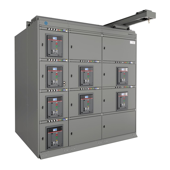
- Page 1 I N S TA L L AT I O N , O P E R AT I O N S A N D M A I N T E N A N C E M A N UA L ReliaGear® LV SG Low voltage switchgear...
- Page 2 These instructions convey information that pertains to ReliaGear® LV SG low voltage switchgear. These instructions do not purport to cover all details or variations in equipment nor to provide for every possible contingency to be met in connection with installation, operation or maintenance.
-
Page 3: Table Of Contents
TA B L E O F C O N T E N T S Table of contents Warranty and general information 04– 06 Introduction 07– 13 Receiving, handling and storage 14 – 27 Switchgear description 28 – 43 Equipment installation 44 –... -
Page 4: Warranty And General Information
R E L I A G E A R ® LV S G LO W V O LTA G E S W I TC H G E A R Warranty and general information Hazard classifications All third-party trademarks are the property of their The following important highlighted information respective owners. -
Page 5: Introduction
I N S TA L L AT I O N , O P E R AT I O N S A N D M A I N T E N A N C E M A N U A L Introduction DANGER General information... - Page 6 R E L I A G E A R ® LV S G LO W V O LTA G E S W I TC H G E A R — Testing and Inspection: reviews items which In addition to instruction books, the following As- should be tested or inspected prior to energizing built documentation will be supplied as required ReliaGear LV SG...
-
Page 7: Receiving, Handling And Storage
I N S TA L L AT I O N , O P E R AT I O N S A N D M A I N T E N A N C E M A N U A L Receiving, handling and storage Receiving Inspecting for damage... - Page 8 R E L I A G E A R ® LV S G LO W V O LTA G E S W I TC H G E A R — Packaging of loose material for shipment Spare compartment Carton containing loose material Shipping label —...
- Page 9 DANGER I N S TA L L AT I O N , O P E R AT I O N S A N D M A I N T E N A N C E M A N U A L WARNING CAUTION —...
- Page 10 R E L I A G E A R ® LV S G LO W V O LTA G E S W I TC H G E A R — Location of lifting plates of outdoor enclosure 1. Lifting plate 2.
- Page 11 I N S TA L L AT I O N , O P E R AT I O N S A N D M A I N T E N A N C E M A N U A L Spreaders and timber not Front...
- Page 12 R E L I A G E A R ® LV S G LO W V O LTA G E S W I TC H G E A R — Lifting plates must be removed where Method of rolling sections are joined equipment into place Roller DANGER...
- Page 13 I N S TA L L AT I O N , O P E R AT I O N S A N D M A I N T E N A N C E M A N U A L Jacks —...
- Page 14 R E L I A G E A R ® LV S G LO W V O LTA G E S W I TC H G E A R DANGER WARNING Storage Caution: If the space heaters are to CAUTION be temporarily energized from Switchgear external source, it is important to...
-
Page 15: Switchgear Description
I N S TA L L AT I O N , O P E R AT I O N S A N D M A I N T E N A N C E M A N U A L Switchgear description —... - Page 16 R E L I A G E A R ® LV S G LO W V O LTA G E S W I TC H G E A R — All of the primary circuit switching and protective The breakers are provided with self-aligning devices, secondary control and metering devices, primary and secondary disconnecting contacts, Outline of a typical load...
- Page 17 I N S TA L L AT I O N , O P E R AT I O N S A N D M A I N T E N A N C E M A N U A L —...
- Page 18 R E L I A G E A R ® LV S G LO W V O LTA G E S W I TC H G E A R — Breaker compartment Closed-door draw-out circuit breaker Emax 2 circuit breaker compartment compartments are standard construction with all —...
- Page 19 I N S TA L L AT I O N , O P E R AT I O N S A N D M A I N T E N A N C E M A N U A L DANGER —...
- Page 20 R E L I A G E A R ® LV S G LO W V O LTA G E S W I TC H G E A R — Primary disconnect shutters Primary disconnect shutters, Figure 23, are Primary disconnect shutter assembly (shown equipped as a standard to provide protection in closed position)
- Page 21 I N S TA L L AT I O N , O P E R AT I O N S A N D M A I N T E N A N C E M A N U A L —...
- Page 22 R E L I A G E A R ® LV S G LO W V O LTA G E S W I TC H G E A R — Compartments for future breakers • Mounting and wiring of additional metering, When specified, compartments may be supplied for relaying, and control devices requiring more Inside of Future breaker...
- Page 23 I N S TA L L AT I O N , O P E R AT I O N S A N D M A I N T E N A N C E M A N U A L —...
- Page 24 R E L I A G E A R ® LV S G LO W V O LTA G E S W I TC H G E A R — Busing system Bus bars are fully tin-plated copper with bolted Main breaker arrangement joints and silver plating is optional.
- Page 25 I N S TA L L AT I O N , O P E R AT I O N S A N D M A I N T E N A N C E M A N U A L —...
- Page 26 R E L I A G E A R ® LV S G LO W V O LTA G E S W I TC H G E A R — Feeder cable and busway The rear cable and terminal compartment, Figure 38 Bus system provides for cable installation and terminations.
- Page 27 I N S TA L L AT I O N , O P E R AT I O N S A N D M A I N T E N A N C E M A N U A L —...
- Page 28 R E L I A G E A R ® LV S G LO W V O LTA G E S W I TC H G E A R — Outdoor switchgear Space heaters, Figure 42 are provided as standard Switchgear designed for outdoor installations is equipment.
-
Page 29: Equipment Installation
I N S TA L L AT I O N , O P E R AT I O N S A N D M A I N T E N A N C E M A N U A L Equipment installation —... - Page 30 R E L I A G E A R ® LV S G LO W V O LTA G E S W I TC H G E A R — Foundation preparation - indoor equipment ABB switchgear and load center substations Refer to Figure 44 along with the owner's are frequently mounted on steel floors and/or Indoor enclosure...
- Page 31 I N S TA L L AT I O N , O P E R AT I O N S A N D M A I N T E N A N C E M A N U A L —...
- Page 32 R E L I A G E A R ® LV S G LO W V O LTA G E S W I TC H G E A R — Plan view at level "A" Outdoor walk-in enclosure anchor locations RELIAGEAR LV SG —...
- Page 33 I N S TA L L AT I O N , O P E R AT I O N S A N D M A I N T E N A N C E M A N U A L —...
- Page 34 R E L I A G E A R ® LV S G LO W V O LTA G E S W I TC H G E A R — 2. Remove the shipping skids - The equipment is fastened to the shipping skids with ½ inch lag View showing method of attaching equipment to screws through the equipment anchoring holes.
- Page 35 I N S TA L L AT I O N , O P E R AT I O N S A N D M A I N T E N A N C E M A N U A L DANGER WARNING —...
- Page 36 R E L I A G E A R ® LV S G LO W V O LTA G E S W I TC H G E A R — Neutral bus The neutral bus may be insulated from the Plan view of neutral bus splice installation grounded frame of the switchgear equipment;...
- Page 37 I N S TA L L AT I O N , O P E R AT I O N S A N D M A I N T E N A N C E M A N U A L —...
- Page 38 R E L I A G E A R ® LV S G LO W V O LTA G E S W I TC H G E A R — 10. Connect the transformer secondary - Cross-section view of The installation of the transformer connection assembled roof joint straps to the incoming bus should be done in —...
- Page 39 I N S TA L L AT I O N , O P E R AT I O N S A N D M A I N T E N A N C E M A N U A L —...
- Page 40 R E L I A G E A R ® LV S G LO W V O LTA G E S W I TC H G E A R — Indoor equipment weld anchoring — Spectra series* busway mounting (front-entry) Elevation Rear Plan view...
- Page 41 I N S TA L L AT I O N , O P E R AT I O N S A N D M A I N T E N A N C E M A N U A L —...
- Page 42 R E L I A G E A R ® LV S G LO W V O LTA G E S W I TC H G E A R This should result in the oozing of compound Make five revolutions around the "B" and "C" phase —...
- Page 43 I N S TA L L AT I O N , O P E R AT I O N S A N D M A I N T E N A N C E M A N U A L —...
- Page 44 R E L I A G E A R ® LV S G LO W V O LTA G E S W I TC H G E A R — After the sections have been aligned and bolted After the splice plates have been installed, run together, on each shipping split section remove the the breaker lifting device over the assembled Switchgear shipping...
-
Page 45: Installing And Removing Circuit
I N S TA L L AT I O N , O P E R AT I O N S A N D M A I N T E N A N C E M A N U A L Installing and removing circuit breakers General... - Page 46 DANGER R E L I A G E A R ® LV S G LO W V O LTA G E S W I TC H G E A R WARNING CAUTION — 3. Attach the appropriate lifting beam, Table 6, to Notice: If a breaker is rejected by the NOTICE the circuit breaker's lifting plates as shown in...
- Page 47 I N S TA L L AT I O N , O P E R AT I O N S A N D M A I N T E N A N C E M A N U A L —...
- Page 48 R E L I A G E A R ® LV S G LO W V O LTA G E S W I TC H G E A R 3. Open the compartment door and fully extend the Removing the circuit breakers DANGER draw-out rails.
-
Page 49: Testing And Inspection
I N S TA L L AT I O N , O P E R AT I O N S A N D M A I N T E N A N C E M A N U A L Testing and inspecting General General instructions for setting the relays are... - Page 50 R E L I A G E A R ® LV S G LO W V O LTA G E S W I TC H G E A R Key interlocks Complete Instructions for testing the trip units After initial installation of the switchgear are included with the test set.
- Page 51 I N S TA L L AT I O N , O P E R AT I O N S A N D M A I N T E N A N C E M A N U A L For specific wiring diagrams related to your order, For generic wiring diagram, please see please review the As-Built documentation.
-
Page 52: Cooling Fan Control Module
R E L I A G E A R ® LV S G LO W V O LTA G E S W I TC H G E A R Cooling fan control module — General Refer the Cooling Fan Installation and Trip Unit ReliaGear LV SG may be provided with a front- Programming Guide 1VAL106902-TG for more Front-mounted... - Page 53 I N S TA L L AT I O N , O P E R AT I O N S A N D M A I N T E N A N C E M A N U A L —...
- Page 54 R E L I A G E A R ® LV S G LO W V O LTA G E S W I TC H G E A R Operation • Amber current under set value indicating light is A three position Illuminated Fan Control Switch, not illuminated Figure 85, is provided to allow an operator to select •...
-
Page 55: Operating The Switchgear
I N S TA L L AT I O N , O P E R AT I O N S A N D M A I N T E N A N C E M A N U A L Operating the switchgear Circuit breaker operation Opening operation... - Page 56 R E L I A G E A R ® LV S G LO W V O LTA G E S W I TC H G E A R — Draw-out operation All breakers are supported on the draw-out rails Breaker shown in CONNECT position mounted on the side walls of the cradle.
- Page 57 I N S TA L L AT I O N , O P E R AT I O N S A N D M A I N T E N A N C E M A N U A L —...
- Page 58 R E L I A G E A R ® LV S G LO W V O LTA G E S W I TC H G E A R — Switchgear accessories Table 9 - Breaker Kirk lever kit ordering details Future circuit breaker Size Type...
- Page 59 I N S TA L L AT I O N , O P E R AT I O N S A N D M A I N T E N A N C E M A N U A L DANGER —...
-
Page 60: Energizing The Switchgear
R E L I A G E A R ® LV S G LO W V O LTA G E S W I TC H G E A R Energizing the switchgear DANGER Before energizing Energizing procedures WARNING Before switchgear is energized, a thorough Caution: Energizing switchgear for final check should be made using the following CAUTION... -
Page 61: Maintaining The Switchgear
I N S TA L L AT I O N , O P E R AT I O N S A N D M A I N T E N A N C E M A N U A L Maintaining the switchgear Maintenance requirements Wetted equipment... - Page 62 R E L I A G E A R ® LV S G LO W V O LTA G E S W I TC H G E A R DANGER Warning: De-energize equipment In addition to these checks, use a megohm-meter WARNING to test the switchgear.
- Page 63 I N S TA L L AT I O N , O P E R AT I O N S A N D M A I N T E N A N C E M A N U A L Lubrication Breaker compartment interiors DANGER...
- Page 64 R E L I A G E A R ® LV S G LO W V O LTA G E S W I TC H G E A R Bus area 1. Inspect all power cable connections for signs of overheatingand tighten all connections.
- Page 65 I N S TA L L AT I O N , O P E R AT I O N S A N D M A I N T E N A N C E M A N U A L Apply a coat of good acrylic enamel primer Both the primer (Sherwin-Williams E61 A 60) and (Sherman-Williams E61 A 60, part number...
- Page 66 R E L I A G E A R ® LV S G LO W V O LTA G E S W I TC H G E A R Appendix A - torque values Table A.1 - Torque values for low voltage equipment electrical joint hardware other than cable terminals (copper, tin or silver plated) Hardware Size...
- Page 67 I N S TA L L AT I O N , O P E R AT I O N S A N D M A I N T E N A N C E M A N U A L Appendix B - circuit breaker rejection features General...
- Page 68 R E L I A G E A R ® LV S G LO W V O LTA G E S W I TC H G E A R E1.2 UL 1066 800A B-A 1200A B-A 800A N-A 1200A N-A 250A S-A 800A S-A 1200A S-A...
- Page 69 I N S TA L L AT I O N , O P E R AT I O N S A N D M A I N T E N A N C E M A N U A L E2.2 UL 1066 800A S-A 1200A S-A...
- Page 70 R E L I A G E A R ® LV S G LO W V O LTA G E S W I TC H G E A R E4.2 UL1066 3200A S-A 3200A H-A...
- Page 71 I N S TA L L AT I O N , O P E R AT I O N S A N D M A I N T E N A N C E M A N U A L E6.2 UL 1066 3200A H-A 4000A H-A...
- Page 72 R E L I A G E A R ® LV S G LO W V O LTA G E S W I TC H G E A R E2.2 Non-automatic 2000A N-A 800A S-A 1600A S-A 2000A S-A 800A V-A 1600A V-A 2000A V-A...
- Page 73 I N S TA L L AT I O N , O P E R AT I O N S A N D M A I N T E N A N C E M A N U A L E4.2 Non-automatic 3200A S-A 3200A H-A...
- Page 74 R E L I A G E A R ® LV S G LO W V O LTA G E S W I TC H G E A R Appendix C - Circuit breaker information For all circuit breaker information, including ratings, weights, accessories, etc., reference: •...
- Page 75 Overhead Circuit Breaker Lifting Device Crank 673D0500021505 Racking Handle - External to Breaker RSGRH Circuit Breaker Lifting Cart GE-1000 Circuit Breaker Transfer Truck 71-746-02 Future Door Cover (E2.2, E4.2, E6.2) RSGFTDRCVR26 Below is a list of installation manuals to aid in field service activies: •...
- Page 76 305 Gregson Drive Cary, NC 27511 USA abb.com/contacts abb.com/lowvoltage GE is a trademark of GE. Manufactured by ABB Inc. under license from General Electric Company. The information contained in this document is for general information purposes only. While ABB strives to keep the...
Need help?
Do you have a question about the ABB ReliaGear LV SG and is the answer not in the manual?
Questions and answers