Advertisement
Available languages
Available languages
Quick Links
READ IT OR WATCH IT
Read instructions or watch easy-to-
follow video. Scan QR code or visit
https://goo.gl/7QMc7p
Questions? Contact our U.S.-based Consumer Care
at 1-800-654-8483 between 7AM-8PM CST.
B
C
A
E
D
Environmental ratings
Ambient Temperature: –40° to 130° F
Humidity: 0-95% RH, non-condensing
Wiring connections
Screw clamp terminals for up to two 8AWG wires per position. For supply connections at 40A max.
load, use 8AWG or larger wires suitable for at least 105° C. Use copper conductors only.
AWG
A
Read and follow all instructions and warranty information prior to use
to ensure
protection to connected equipment and warranty compliance.
1) Tools you will need
Pliers
14
15
105
º
c
Wire cutters
12
20
Phillips-head screwdriver
10
30
Flat-head screwdriver
8
40
Hammer
2) Pre-installation
Before installation, follow the instructions below to remove knockouts
to route wiring to connection terminals. Knockouts may be made 1/2
in. or 3/4 in.
For 1/2 in. knockout
1. Place small-blade screwdriver into inner ring of knockout circle [FIG 2].
2. Tap down lightly with the screwdriver to punch the 1/2in. knockout loose.
For 3/4in. knockout
1.
Create 1/2in. knockouts as instructed.
2.
Grip outer ring of
knockout circle with pliers.
3.
Gently twist and pull
to remove outer ring and
form 3/4in. knockout.
3) Choose a suitable mounting location
Mounting the box for drywall
1. Hold the box in place and use the three holes highlighted to mark position on the
mounting surface [FIG 3].
2. Drill a 3/16in. size hole for the drywall anchors at each marked location.
3. Insert an anchor in each hole, and gently tap the open end of anchor with a hammer until the
anchor is almost flush with the wall.
4. Mount the box to the anchors using the supplied screws.
Mounting the box for solid surface
1. Hold the box in place and use the three holes highlighted to mark position on the
mounting surface [FIG 3].
2. Drill a 3/32 in. hole at each marked location.
3. Mount the box to the surface using the supplied screws.
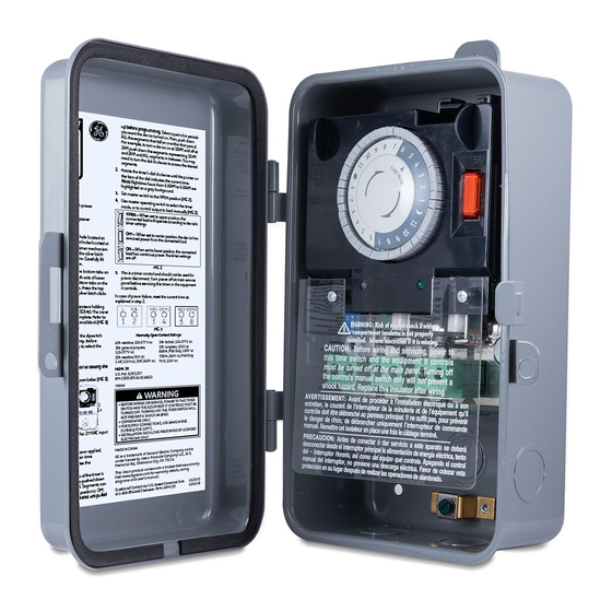
IMPORTANT! Always close the rainproof door after use.
A. Indicator Lights
Orange light — indicates timer is powered
Green light — indicates load is powered
B. Timer Dial
C. Operation Mode Switch
Timer — When set to upper position, the
connected load will operate according
to device's timer settings
Off — when set to center position, power is
removed from the connected load
4) Dipswitch configuration
On — when set to lower position, the
WARNING: Failure to properly configure the dipswitch will damage the unit and void the warranty. Before
connected load has continuous
installation, complete the following steps to select the proper dipswitch configuration.
power and timer settings are off
1. Determine the input voltage.
D. Connection Terminal
E. Dipswitch Configuation
2. Do not apply power to the timer prior to setting the input voltage dipswitch.
3. Set the dipswitch according to the diagram below [FIG 4].
5) Wiring
FIG 1
WARNING SHOCK HAZARD: Turn off the power to the branch circuit for the switch and lighting fixture at
the service panel. All wiring connections must be made with the power off to avoid personal injury and
damage to the switch.
FIG 2
6) Operating instructions
When the timer switch is installed and power applied, the timer's dial turns clockwise to maintain time.
The pointer on the face of the dial indicates the current time.
1. Be sure all segments are pulled up before programming. Select the period or periods you want the
2. The segments around the outer edge of the timer's dial represent 30 minutes and can be pushed down
FIG 3
3. Rotate the timer's dial clockwise until the pointer on the face of the dial indicates the current time.
4. Set master switch to the TIMER position [FIG 6]:
5. This is a timer control and should not be used for power disconnect. Turn power off at main service
Specifications
Input voltage: 120
FIG 4
in all units based upon dipswitch configuration.
Switch rating: DPDT Models
Normally open contact ratings:
40A resistive, 120-277VAC
30A general purpose, 120-277VAC
20A resistive, 30VDC
1 HP, 120VAC; 2HP, 240VAC;
20A ballast, 120-277VAC
15A tungsten, 120VAC
800VA, pilot duty, 120VAC
720VA, 240VAC, pilot duty
TV-5, 120VAC
MADE IN CHINA
GE is a trademark of General Electric Company and is
under license by Jasco Products Company LLC, 10 E.
Memorial Rd., Oklahoma City, OK 73114.
This Jasco product comes with a 1-year limited warranty.
Visit www.byjasco.com for warranty details.
Questions? Contact our U.S.-based Consumer Care at
1-800-654-8483 between 7AM—8PM CST.
device turned on.
using your finger or the tip of a pencil. Segments can be easily pulled up by hand. Up position = OFF,
down position = ON. Then, push down ALL the segments that fall on or within that period. [FIG 5]
Example: To turn a device on at
10PM and off at 2AM, push down the
Each segment
segments representing 10PM and 2AM
represents 30 minutes
and ALL segments in between. You
may need to turn the dial clockwise to
access the desired segments.
FIG 5
Note: Nighttime hours from 6:30PM to 6:30AM are highlighted on a gray background.
TIMER — when set to upper position, the connected load will
operate according to device's timer settings
OFF — when set to center position, the device has removed
power from the connected load
ON — when set to lower position, the connected load has
continuous power. The timer settings are off
FIG 6
panel before servicing this timer or the equipment it controls.
In case of power failure, reset the current time as explained in previous steps.
VAC
, 208/240
VAC
, or 277
VAC
NEMA 3R
U.S. Pat. 6,563,237
Model BM-C303US5-04
YYWW
WARNING
• RECOMMEND INSTALLATION BY LICENSED
ELECTRICIAN.
CAUTION: RISK OF ELECTRIC SHOCK
• MORE THAN ONE DISCONNECT SWITCH MAY BE
REQUIRED TO DE-ENERGIZE THE DEVICE BEFORE
SERVICING.
• HIGH VOLTAGE (THERE MAY BE MORE THAN ONE
SOURCE OF SUPPLY) DISCONNECT ALL POWER
SOURCES BEFORE SERVICING.
• USE COPPER CONDUCTORS ONLY.
• CLOSE THE COVER AFTER USE.
• TIGHTEN CONNECTIONS TO 25 LBF-IN.
• USE CORRECT GAUGE WIRE (8-14 AWG) BASED
ON LOCAL ELECTRICAL CODE OF AT LEAST 80°C
RATING (SINGLE CORE IN 8 AWG).
• RAINTIGHT, APPROVED FOR OUTDOOR USE.
• WIRE STRIP LENGTH 1/2 in.
GROUNDING
• NATIONAL ELECTRICAL CODE REQUIRES
GROUNDING MUST BE CONTINUOUS AND
IN PROPER ELECTRICAL CONTACT IN ALL
GROUNDING CONDUCTORS, METALLIC CONDUITS
AND GROUNDING TERMINALS.
46536 V2
07/31/2019
Advertisement

Related Manuals for GE BM-C303US5-04


Summary of Contents for GE BM-C303US5-04
- Page 1 GROUNDING CONDUCTORS, METALLIC CONDUITS MADE IN CHINA knockout circle with pliers. AND GROUNDING TERMINALS. GE is a trademark of General Electric Company and is NEMA 3R Gently twist and pull under license by Jasco Products Company LLC, 10 E. U.S. Pat. 6,563,237 to remove outer ring and Memorial Rd., Oklahoma City, OK 73114.
- Page 2 U.S. Pat. 6,563,237 2. En cada lugar marcado, perfore un orificio de 3/16” para los anclajes de la pared de yeso. GE es una marca comercial de General Electric Company con Model BM-C303US5-04 3. Introduzca un anclaje en cada orificio y golpee ligeramente el extremo abierto del anclaje con un martillo licencia otorgada a Jasco Products Company LLC, 10 E.
- Page 3 YYWW FABRIQUÉ EN CHINE 3) Choisir un endroit de montage adéquat GE est une marque de commerce de General Electric Installation du boîtier sur une cloison sèche Company et est sous licence par Jasco Products Company LLC, 1. Maintenir le boîtier en place et se servir des trois trous mis en évidence pour marquer son emplacement 10 E.
Need help?
Do you have a question about the BM-C303US5-04 and is the answer not in the manual?
Questions and answers