
Subscribe to Our Youtube Channel
Related Manuals for Paradyne ACCULINK 316x


Summary of Contents for Paradyne ACCULINK 316x
- Page 1 ACCULINK 316x DATA SERVICE UNIT/ CHANNEL SERVICE UNIT (INCLUDES TERMINAL USER INTERFACE) OPERATOR’S GUIDE Document No. 3160-A2-GB22-10 December 1996...
- Page 2 Paradyne Corporation makes no representation or warranties with respect to the contents hereof and specifically disclaims any implied warranties of merchantability or fitness for a particular purpose. Further , Paradyne Corporation reserves the right to revise this publication and to make changes from time to time in the contents hereof without obligation of Paradyne Corporation to notify any person of such revision or changes.
-
Page 3: Important Safety Instructions
Safety Instructions Important Safety Instructions Read and follow all warning notices and instructions marked on the product or included in the manual. This product is intended to be used with a three-wire grounding type plug - a plug which has a grounding pin. This is a safety feature. Equipment grounding is vital to ensure safe operation. - Page 4 ACCULINK 316x DSU/CSU Notices December 1996 3160-A2-GB22-10...
-
Page 5: Government Requirements And Equipment Return
Government Requirements Government Requirements and Equipment Return Certain governments require that instructions pertaining to DSU/CSU and modem connection to the telephone network be included in the installation and operation manual. Specific instructions are listed in the following sections. United States NOTICE TO USERS OF THE UNITED STATES TELEPHONE NETWORK 1. - Page 6 Via the Internet: Visit the Paradyne World Wide Web site at http://www.paradyne.com Via Telephone: Call our automated call system to receive current information via fax or to speak with a company representative.
- Page 7 Government Requirements CAUTION Users should not attempt to make such connections themselves, but should contact the appropriate electric inspection authority, or electrician, as appropriate. The load number is labeled on the equipment. The load number (LN) assigned to each terminal device denotes the percentage of the total load to be connected to a telephone loop which is used by the device to prevent overloading.
-
Page 8: Table Of Contents
Table of Contents Preface Objectives and Reader Assumptions ......Related Documents ........Reference Documents . - Page 9 ACCULINK 316x DSU/CSU Operation Operating the Front Panel ........Configuring the DSU/CSU .
- Page 10 Table of Contents List of Figures Figure Page 3160 DSU/CSU Front Panel ......... . . 3164 DSU/CSU Front Panel .
- Page 11 ACCULINK 316x DSU/CSU Figure Page 3-21 Edit User Screen ........... . 3-26 3-22 Communication Port Options Screen...
- Page 12 Table of Contents List of Tables Table Page Models 3160/3614 DSU/CSUs Rear Panel Connectors ..... . Auxiliary Backplane Connectors ........System LEDs .
- Page 13 ACCULINK 316x DSU/CSU Table Page T1 Network Interface Connector (J4) ........T1 Network Interface Connector (DA15P) .
-
Page 14: Preface
Preface Objectives and Reader Reference Documents Assumptions AT&T Technical Reference 54016 This operator’s guide contains installation and AT&T Technical Reference 62411 operation information for the ACCULINK 316x Data ANSI T1.403-1989 Service Unit (DSU)/Channel Service Unit (CSU). DOC Certification Standard CS-03 CSA-22.2 No. -
Page 15: Introduction
Introduction Overview ................Features . -
Page 16: Features
ACCULINK 316x DSU/CSU User Interface Independently selectable DTE interfaces (V.35, EIA-530A, V.11, and/or RS449/422). There are three ways of accessing the user interface: Flexible timing source, available from the Front panel – provides an LCD and a keypad T1 network interface, the DSX-1 T1 interface, at which enable you to display information about and least one of the synchronous DCE data ports, an interact with the DSU/CSU. -
Page 17: Front Panel Emulation
Introduction Front Panel Emulation Procedures throughout this manual are described specifically for a front panel user. Look for the subhead The 3160/3164 DSU/CSU offers the same functionality Differences Using the Async Terminal within each through Front Panel Emulation software as that provided procedure section for the user interface information on the by the DSU/CSU front panel. -
Page 18: Acculink 316X Dsu/Csu Physical Description
ACCULINK 316x DSU/CSU SNMP is an industry-standard network management ACCULINK 316x DSU/CSU system that is used to monitor network performance and Physical Description status, and to report alarms (i.e., traps). To function, SNMP requires a manager consisting of a software The ACCULINK 316x DSU/CSU series of products program housed within a workstation;... -
Page 19: Dsu/Csu Front Panel
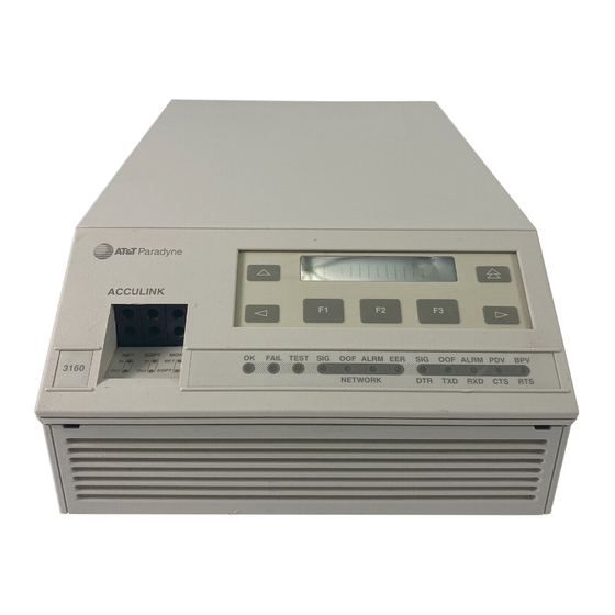
Introduction KEYPAD ACCULINK EQPT FAIL TEST OOF ALRM ALRM PDV NETWORK 496-14539-03 TEST JACKS LEDs Figure 1-1. 3160 DSU/CSU Front Panel ACCULINK EQPT FAIL TEST OOF ALRM ALRM PDV 3164 NETWORK 496-14566-01 Figure 1-2. 3164 DSU/CSU Front Panel 3160-A2-GB22-10 December 1996... -
Page 20: Dsu/Csu Rear Panel
ACCULINK 316x DSU/CSU Figure 1-3. 3160 DSU/CSU Rear Panel Figure 1-4. 3164 DSU/CSU Rear Panel December 1996 3160-A2-GB22-10... - Page 21 Introduction Table 1-1 Models 3160/3164 DSU/CSUs Rear Panel Connectors Connector Name Function POWER A modular connector that supplies power to the DSU/CSU. AUX PORT An auxiliary communications port for future use. COM PORT A communications port that provides access to the front panel from a locally connected PC.
-
Page 22: Dsu/Csu Faceplate
ACCULINK 316x DSU/CSU Carrier-Mounted Model 3161 DSU/CSU The 3161 DSU/CSU is a circuit card that is installed into the 3000 Series Carrier. A single carrier can house up Select to 16 DSU/CSUs; the DSU/CSUs are controlled by the Fail Test carrier’s Shared Diagnostic Control Panel (SDCP), which can control up to eight carriers. -
Page 23: Auxiliary Backplane
Introduction Figure 1-6. Auxiliary Backplane 3160-A2-GB22-10 December 1996... -
Page 24: Installation
Installation Overview ................Planning . -
Page 25: Example Point-To-Point Configuration
ACCULINK 316x DSU/CSU In addition, a 3160 DSU/CSU, acting as an SNMP Serial connection via the COM or MODEM port agent, can be connected to and managed from an SNMP (using PPP or SLIP) through a network device (e.g., management system in one of two ways: router) that supports IP routing to the network management system (Figure 2-6). -
Page 26: Multiport T1 Dsu/Csu In A Fractional T1 Network Configuration
Installation ACCULINK 3160/3164 DSU/CSU ROUTER FRACTIONAL T1 NETWORK ACCULINK 3160/3164 DSU/CSU ACCULINK 3160/3164 DSU/CSU ROUTERS ROUTER 496-14313a-01 Figure 2-3. Multiport T1 DSU/CSU in a Fractional T1 Network Configuration Figure 2-4. Central-Site T1 Termination Configuration 3160-A2-GB22-10 December 1996... -
Page 27: Serial Connection To Snmp
ACCULINK 316x DSU/CSU Figure 2-5. Serial Connection to SNMP Figure 2-6. Serial Connection through a Router to SNMP December 1996 3160-A2-GB22-10... -
Page 28: Box Contents
Installation Box Contents HANDLING PRECAUTIONS The 3160/3164 DSU/CSU product arrives in a single STATIC-SENSITIVE DEVICES box and should contain the following: This product is designed to protect One 3160/3164 DSU/CSU standalone unit sensitive components from damage due to electrostatic discharge (ESD) One 14.5 foot VF cable during normal operation. -
Page 29: Optional Power Selection
ACCULINK 316x DSU/CSU 5. If you intend to manage the 3160/3164 DSU/CSU in Chapter 3, Operation, and to Appendix C, with SNMP, cable either the COM or MODEM Configuration Options. port (as appropriate for your configuration). Then, configure the SNMP management link. See Chapter 3, Operation, and Appendix C, Optional Power Selection Configuration Options, for more information. -
Page 30: Vdc Single Source Power Supply Pinouts
Installation Installing the Single –48 Vdc Power Supply 2. Connect the green wire to a suitable earth ground. 3. Connect the orange and blue wires to the – 48 Vdc To install the 3160/3164 DSU/CSU using a single input source. source –... -
Page 31: Vdc Redundant Source Power Supply Pinouts
ACCULINK 316x DSU/CSU Installing the Redundant –48 Vdc Power 3. Connect the green wire to a suitable earth ground. Supply 4. Connect the orange wire to the –48 Vdc input source B. To install the 3160/3164 DSU/CSU using a redundant –... -
Page 32: Power-Up Self-Test
Installation Power-Up Self-Test 3. If the self-test is successful, the Passed screen appears for one second, the Fail LED is turned Off and the OK LED lights. After you connect the 3160/3164 DSU/CSU to a power outlet, the power-up self-test is performed to ensure that the unit is in good working order. -
Page 33: Selecting A Model 3161 Dsu/Csu
ACCULINK 316x DSU/CSU Differences Using the Async Terminal: To monitor the DSU/CSU Identity self-test from the async terminal, select Health, Test Status, and Self Test Results from the main/status menu. The identity of the 316x DSU/CSU (serial number, The full screen display capacity provides a complete test model number, software revision level, hardware revision results screen that includes the self-test results. - Page 34 Installation 4. The following screens appear in the order listed To change the customer ID, each time you press the key. 1. Press the key on the top-level menu to bring the Ctrl branch onto the front panel LCD. Identity: Ser=xxxxxxx DSU ESF Stat...
-
Page 35: Establishing Access Security On A Port
ACCULINK 316x DSU/CSU 6. Enter the desired ID. Press F1 (Up) and F2 (Down) to scroll up and down through the valid main/configuration/edit/user Customer ID: New Cust Model: ACCULINK XXXX characters/numbers for the customer ID. Valid characters are 0 through 9, #, -, ., /, A to Z, and User blank space. -
Page 36: Password Configuration Screen
Installation To set a password, 6. Enter the desired password. Press F1 (Up) and F2 (Down) to scroll up and down through the 1. Press the key on the top-level menu screen to valid characters/numbers for the password. Valid bring the Ctrl branch onto the front panel LCD. password characters are 0–9, a–z, A–Z, #, –, ., and /. -
Page 37: 3160/3164 Dsu/Csu Cabling
ACCULINK 316x DSU/CSU 3160/3164 DSU/CSU Cabling COM port cable to locally connect a PC. A dc voltage power cable for the –48 Vdc The 3160/3164 DSU/CSU is supplied with an ac power redundant source, –48 Vdc single source, and transformer and a VF cable for the integral modem. You +24 Vdc power source. -
Page 38: Dsu/Csu Cabling Configurations
Installation Figure 2-13. 3160/3164 DSU/CSU Cabling Configurations 3160-A2-GB22-10 December 1996 2-15... -
Page 39: Factory Default Configuration Options
ACCULINK 316x DSU/CSU Factory Default Configuration To install Front Panel Emulation software, Options 1. Insert the diskette into the appropriate drive. 2. Select File from Program Manager. The 316x DSU/CSU arrives with two preset factory default configuration settings. These settings are based on 3. -
Page 40: Enabling/Disabling The Front Panel
Installation Enabling/Disabling the Front 3. Press F1 to select Edit. Panel Choose Funct: You can enable or disable the display of data through Edit Save the front panel. This feature is useful for ensuring that other users do not inadvertently change the device’s configuration options while you are using the PC or async terminal interface. - Page 41 ACCULINK 316x DSU/CSU 3160/3164 DSU/CSU User You can only reach the screen that controls security access using the front panel; you cannot access this option Interface Access Security using front panel emulation, async terminal, or the modem interface. The user interface access security option allows you to The procedure for changing user interface access limit access to the 3160/3164 DSU/CSU to display-only security levels appears on the following tear-out page.
- Page 42 Installation 3. Press the key once. NOTE This page of the manual is self- DSU ESF supporting and can be removed to Stat Test Cnfig prevent unwanted knowledge of the security access levels and their selection. The Security screen appears. Changing User Interface Access Security To change user interface access security, Security:...
-
Page 43: Operation
Operation Operating the Front Panel ............. . - Page 44 ACCULINK 316x DSU/CSU Controlling the DSU/CSU ............3-61 Acquiring/Releasing the User Interface .
-
Page 45: Operating The Front Panel
Operation Operating the Front Panel NOTE The 3160 DSU/CSU front panel (Figure 3-1) consists You can display a graphical of an LCD that displays messages, a keypad, 12 LEDs, representation of the 316x and six test jacks. The Model 3161 CSU faceplate DSU/CSU front panel on an contains these same 12 LEDs and six test jacks (see attached PC. -
Page 46: Model 3161 Dsu/Csu Faceplate
ACCULINK 316x DSU/CSU Select Fail Test Alrm LEDS Alrm TEST JACKS DSU/CSU 3161 496-14543-01 Figure 3-2. Model 3161 DSU/CSU Faceplate CARRIER SLOTS 1–16 Select COMSPHERE 3000 OK Alarm BckUp Test 496-14392-01 SELECT STATUS KEYPAD LCD DISPLAY INDICATORS Figure 3-3. Shared Diagnostic Control Panel (SDCP) December 1996 3160-A2-GB22-10... -
Page 47: Lcd
Operation Context-Sensitive Menu The LCD displays messages and the front panel menu This DSU/CSU is an intelligent device that displays in an easy-to-read English format, including easily only valid options for the current configuration. recognizable abbreviations and symbols (Figure 3-4). Therefore, you are only presented with menu choices that are consistent with the current configuration and operational state of the DSU/CSU;... -
Page 48: Leds
ACCULINK 316x DSU/CSU LEDs Use the Function (F1, F2, F3) keys to make selections from the choices presented on the second line of the LCD. There are twelve LEDs on the 3160/3164 DSU/CSU When this line presents choices, it is generally divided front panel (Figure 3-6) as well as on the 3161 DSU/CSU into three sections, each displayed directly above one of faceplate. -
Page 49: System Leds
Operation Table 3-1 System LEDs Name Color Meaning Green Indicates the current operational state of the DSU/CSU. ON : The DSU/CSU is operational and has power. OFF : The DSU/CSU is performing a power-up self-test or a system failure has occurred. BLINKING : A software download is in progress. -
Page 50: Network Interface Leds
ACCULINK 316x DSU/CSU Table 3-2 NETWORK Interface LEDs Name Color Meaning Green Monitors the signal being received from the network. ON : A recoverable signal is being received from the network. OFF : The signal cannot be recovered from the network (a Loss of Signal condition exists). -
Page 51: Dsx-1 Drop/Insert Port Leds
Operation Table 3-3 DSX-1 Drop/Insert Port LEDs Name Color Meaning Green Monitors the signal being received from the DSX-1. ON : A recoverable signal is being received from the DSX-1. OFF : The signal cannot be recovered from the DSX-1 (a Loss of Signal condition exists). -
Page 52: Data Port Leds
ACCULINK 316x DSU/CSU Table 3-4 Data Port LEDs Name Color Meaning Green Monitors the state of interchange circuit CD (CCITT 108/1, /2) – DTE Ready received from the DTE. ON : DTR is being asserted by the DTE. OFF : DTR is not being asserted. -
Page 53: Displaying Led Conditions On The Front Panel
Operation Displaying LED Conditions on the Front Panel 4. From the Select LEDs screen, press the function key that corresponds to the T1 or port for which The same conditions monitored by the front panel you want to display LEDs. Use the scroll keys, if LEDs can also be monitored by the LED command. -
Page 54: Led Status Screen
ACCULINK 316x DSU/CSU 2. Press F3 to select Ctrl. main/status/leds Customer ID: New Cust Model: ACCULINK XXXX DSU ESF LEDs Test Cnfig Ctrl NET T1 DTE T1 Port1 Port2 Port3 Port4 Test Alrm Alrm 3. From the Ctrl screen, press F3 to select LED. Control: Call Refresh Main Previous Cntrl–x to Disconnect... -
Page 55: Led Display Selection Screen
Operation Figure 3-8 shows an example of this selection screen. The 3161 front panel emulation screen (Figure 3-10) You can set the front panel LED display to be DTE or a looks the same as the 3160/3164 DSU/CSU screen, except port. -
Page 56: Dsu/Csu Test Jacks
ACCULINK 316x DSU/CSU Table 3-5 Front Panel Emulation Screen Icons Icon Name Meaning Help Help Click on this pull-down menu to display online HELP. Options Options Click on this pull-down menu to access the following options: Phone Numbers Open COM Window Change MDM Cmds Exit Stop/Go Light... -
Page 57: Test Jack Block Diagram
Operation Figure 3-12. 3161 DSU/CSU Test Jacks Figure 3-13. Test Jack Block Diagram 3160-A2-GB22-10 December 1996 3-15... -
Page 58: Configuring The Dsu/Csu
ACCULINK 316x DSU/CSU Table 3-6 Test Jack Functions Test Jack Name Function Net In A break-in and test jack that allows a signal to be inserted toward the network by external test equipment. The signal is inserted on the DSX-1 side of the (Network In) DSU/CSU. -
Page 59: Configuration Branch For The Front Panel
Operation Configuration Procedures Use the Configuration (Cnfig) branch of the front panel menu tree to display or change DSU/CSU configuration options (see Figure 3-14). Figure 3-14. Configuration Branch for the Front Panel 3160-A2-GB22-10 December 1996 3-17... -
Page 60: Configuration Branch For The Async Terminal
ACCULINK 316x DSU/CSU Displaying/Editing Configuration Options Differences using the Async Terminal: Figure 3-15 shows the Configuration branch for the async terminal To display/edit configuration options, interface. 1. Press F3 to select Cnfig from the top-level menu screen. DSU ESF Stat Test Cnfig 2. -
Page 61: Load From Screen
Operation 4. From the Edit screen, select the functional group main/configuration you want to edit by pressing the appropriate Model: ACCULINK XXXX Customer ID: New Cust function key. Use the scroll keys, if necessary. Edit: Load From: ______ Port The configuration options for the selected functional group appear on the front panel one option at a time. -
Page 62: Saving Edit Changes
ACCULINK 316x DSU/CSU The bottom of the screen shows the addition of the Edit 1. From the Choose Function screen (one level above and Save functions. the Edit screen, two levels below the top-level menu screen), press F2 to select Save. The Save To: field can be populated with Active or Cust to enable a 1-step copy of one configuration option set into another when the Save function is subsequently... -
Page 63: Save Edit Screen
Operation Selecting a Specific Port To protect you from accidentally exiting an edit session before saving your changes, the system prompts Save To select a specific port to configure, Options? if you select either Main or Cntrl-x from an edit screen (see Figure 3-18). If you respond No, the 1. -
Page 64: Port Options Configuration Worksheets
ACCULINK 316x DSU/CSU Differences Using the Async Terminal: To select a port, use the Ports selection from the main/configuration/edit menu. The subsequent ports menu provides a list of the configured ports (see Figure 3-19). Prt3 Prt1 Value Value Options Options Port Type E530, V.35, RS449 Port Type... -
Page 65: To Copy To One Or All Ports
Operation To Copy to One or All Ports 5. From the Port Select screen, press F1 (Copy). To copy the configuration options to one or all ports, Port Select: 1. Press F3 to select Cnfig from the top-level menu Copy Prt1 Prt2 screen. -
Page 66: Snmp System Options Screen
ACCULINK 316x DSU/CSU Configuring the 3160/3164 DSU/CSU for main/configuration/edit/snmp/system SNMP Management Customer ID: New Cust Model: ACCULINK XXXX To configure a 3160/3164 DSU/CSU for management SNMP by an SNMP management system you must, System Name: Clear Select and configure the port (COM or MODEM) System Location: Clear providing the link to the SNMP management... - Page 67 Operation To select the MODEM port as the link to the SNMP 6. Press the F1 (Next) key until the Modem Use manager from the front panel, configuration option appears. 1. Press F3 to select Cnfig from the top-level menu screen.
-
Page 68: Edit User Screen
ACCULINK 316x DSU/CSU 3. Press F1 to select Edit. Differences Using the Async Terminal: To select the port to be used for SNMP communications, use the main/configuration/edit/user screen to set the Use field to SNMP for the appropriate port type. Figure 3-21 shows Choose Funct: an example of this screen. - Page 69 Operation To assign an IP address to the MODEM port, 6. Press F1 to select Gen from the SNMP Config screen. 1. Press F3 to select Cnfig from the top-level menu screen. SNMP Config: Trap DSU ESF Stat Test Cnfig 7.
-
Page 70: Selecting The Link Layer Protocol
ACCULINK 316x DSU/CSU Selecting the Link Layer Protocol 9. Use the keys to position the cursor under the digit you want to change. Press F1 (Up) You have the option of selecting either PPP or SLIP as to increment the digit or F2 (Down) to decrement the link layer protocol. -
Page 71: Specifying The Community Name(S) And Access Type(S)
Operation 2. Select the configuration option set to be copied 7. Press the F1 (Next) key until the Modem Link into the Edit area by using the appropriate configuration option appears. function key. Use the scroll keys, if necessary. System Name: Load from: Next Edit... - Page 72 ACCULINK 316x DSU/CSU 2. Select the configuration option set to be copied 7. Press the F1 (Next) key until the into the Edit area by using the appropriate CommunityName1 configuration option appears. function key. Use the scroll keys, if necessary. System Name: Load from: Next...
-
Page 73: Snmp Traps
Operation SNMP Traps 10. When you are through changing the community name, you must press F3 (Save) to save the value. A trap is an unsolicited message that is sent from the Otherwise, the original value will be retained. DSU/CSU to an SNMP manager when the device detects certain, prespecified conditions. -
Page 74: Selecting The Number Of Trap Managers
ACCULINK 316x DSU/CSU Selecting the Number of Trap Managers 4. Press the key from the Edit screen to display the SNMP selection. If you intend to issue traps to an SNMP manager(s) from this device, you must specify the number of SNMP managers that are to receive the traps. -
Page 75: Configuring An Ip Address For Snmp Trap Manager
Operation 3. Press F1 to select Edit. main/configuration/edit/snmp/traps Model: ACCULINK XXXX Customer ID: New Cust Choose Funct: Trap Options Number of Trap Managers: 6 Edit Save Trap Manager 1 IP Address: 000 000 000 000 Clear Trap Manager 2 IP Address: Clear Trap Manager 3 IP Address: Clear... -
Page 76: Configuring Ds0 Channels
ACCULINK 316x DSU/CSU 8. Press F2 (Edit) to edit the IP address. You have the To complete the configuration worksheets for DS0 option of using F3 (Clear) to reset the IP address channel allocation: to the factory default 000.000.000.000. Refer to 1. -
Page 77: Example Channel Allocation
Operation Figure 3-24. Example Channel Allocation 3160-A2-GB22-10 December 1996 3-35... -
Page 78: Example Interface Tables
ACCULINK 316x DSU/CSU Network T1 Interface DSX-1 (DTE) Drop/Insert T1 Interface Network Channel Allocation Drop/Insert Channel Allocation Prt1 Prt1 Prt1 Prt1 Prt1 Prt1 Prt3 Prt2 Prt2 Prt2 Prt2 Prt2 Prt2 Prt2 Prt2 Prt2 Prt2 Prt3 Allocations Allocations D1 – D24 indicates allocation to DSX-1 N1 –... -
Page 79: Ds0 Channels Containing Rbs Information Worksheet
Operation DTE Chan Assign: Voice Config (N1 – 24) (RBS or Data) Data Figure 3-26. DS0 Channels Containing RBS Information Worksheet 3160-A2-GB22-10 December 1996 3-37... -
Page 80: Example Port Channel Configuration Tables (Ports 1 And 2) Worksheet
ACCULINK 316x DSU/CSU Port Chan Options Value Conf Assign To NET, DTE Assign By Block, ACAMI, Chan Port Rate Nx64: 64, 128, 192, 256, 320, 384, 448, 512, 576, 640, 704, 768, 832, 896, 960, 1024, 1088, 1152, 1216, 1280, 1344, 1408, 1472, 1536 Nx56: 56, 112, 168, 224, 280, 336, 392, 448, 504, If Assign By Block 560, 616, 672, 728, 784, 840, 896, 952, 1008, 1064,... -
Page 81: Example Port Channel Configuration Tables (Ports 3 And 4) Worksheet
Operation Port Chan Options Value Conf Assign To NET, DTE Assign By Block, ACAMI, Chan Port Rate Nx64: 64, 128, 192, 256, 320, 384, 448, 512, 576, 640, 704, 768, 832, 896, 960, 1024, 1088, 1152, 1216, 1280, 1344, 1408, 1472, 1536 Nx56: 56, 112, 168, 224, 280, 336, 392, 448, 504, If Assign By Block 560, 616, 672, 728, 784, 840, 896, 952, 1008, 1064,... -
Page 82: Display Channel Symbols
ACCULINK 316x DSU/CSU Displaying DS0 Channel Assignments 2. Select the configuration option set to be copied into the Edit area by using the appropriate Use the Display command for channel configuration to function key. Use the scroll keys, if necessary. view how the DS0 channels for either the DSX-1 Drop/Insert T1 interface or the Network interface are currently allocated. -
Page 83: Display Channels Screen
Operation 7. From the Display Chan screen, press F1 (NET) to If you pressed F2 (DTE), the channels allocated to display the channels allocated to the Network T1 the DSX-1 Drop/Insert T1 interface are displayed. interface. Line 1 displays the 24 channels for the DSX-1 Drop/Insert T1 interface, while Line 2 displays what is allocated to the DS0 channel shown in Line 1. -
Page 84: Allocating Data Ports
ACCULINK 316x DSU/CSU Allocating Data Ports NOTE You have the capability of assigning a specific port For the 3164 DSU/CSU, there is a (Prt1...Prt2 for Models 3160/3161, Prt1...Prt4 for hardware limitation that limits the Model 3164) to DS0 channels on either the Network combined bandwidth used by interface or the DSX-1 Drop/Insert T1 interface using the Port1 and Port3 to a total of... -
Page 85: Block Channel Assignment Method Example
Operation 3. Press F1 to select Edit. 8. The configuration option for the data port channel allocation destination appears on the screen. Press F2 (NET) to assign this port to the Network T1 interface, or F3 (DTE) to assign this Choose Funct: port to the DSX-1 Drop/Insert T1 interface. -
Page 86: Acami Channel Assignment Method Example
ACCULINK 316x DSU/CSU 3. Use the key to scroll the desired port Start At:Clear rate onto the screen. Rates scroll in groups of Next Clear three. Available selections depend on the current base rate selected for the port. Press the corresponding Function key to select the port rate. -
Page 87: Individual Channel Assignment Method Example
Operation 4. The Start At screen displays the configuration 3. Press F1 (Next) to display the next configuration option used to select the starting DS0 channel. If option (channel allocation). the destination selected is the Network T1 interface, then the Network channels appear on the screen. - Page 88 ACCULINK 316x DSU/CSU 2. Select the configuration option set to be copied 6. From the Channel Config screen, press F3 to into the Edit area by using the appropriate select DTE. function key. Use the scroll keys, if necessary. Channel Config: Dsply Clear Load from:...
-
Page 89: Dte Assignment Screen
Operation Differences Using the Async Terminal: To allocate DS0 3. Press the Function key below the network channel channels from the DSX-1 Drop/Insert T1 interface to the desired. Line 1 displays the 24 DS0 channels for Network interface, select DTE Assign from the the DSX-1 Drop/Insert T1 interface. -
Page 90: Clearing Ds0 Channel Allocation
ACCULINK 316x DSU/CSU Clearing DS0 Channel Allocation 5. Press F3 to select Chan. You can clear (unallocate) all the DS0 channels currently allocated to either the Network T1 interface or Edit: the DSX-1 Drop/Insert T1 interface. Port Chan To clear DS0 channel allocation, 1. -
Page 91: Timing
Operation Timing NOTE The 316x DSU/CSU provides the ability to select a For Model 3161 DSU/CSUs, the master clock (timing) source that is used to synchronize external clock provides timing for all of the T1 and data port interfaces on the DSU/CSU. up to eight slots in the carrier. -
Page 92: Configuring For Network Timing Example
ACCULINK 316x DSU/CSU Configuring for Network Timing Example 5. Press F3 to select Gen for the general configuration options. To configure network timing, 1. Press F3 to select Cnfig from the top-level menu Edit: screen. Chan DSU ESF Stat Test Cnfig 6. -
Page 93: Configuring For External Timing Example
Operation Configuring for External Timing Example 6. The Generate Yellow Alarm configuration option displays first. Press F1 (next) once to display the To configure network timing, DSU/CSU Clock Source configuration option. 1. Press F3 to select Cnfig from the top-level menu screen. -
Page 94: Selecting The Shared Communication Port
ACCULINK 316x DSU/CSU Selecting the Shared 3. Select the configuration option set to be copied into the Edit area by using the appropriate Communication Port function key. Use the scroll keys, if necessary. Communication between the Model 3161 DSU/CSUs in the 3000 Series Carrier and an external PC (attached Load from: either locally or through an external modem) occurs Activ... -
Page 95: Checking The Status Of The Dsu/Csu
Operation 8. Press F2 to select Enab. Differences Using the Async Terminal: Figure 3-34 shows the menu hierarchy for the Status branch when using the async terminal. MasterCom:Disab Next Enab Disab Checking the Status of the Figure 3-34. Async Terminal Status Branch DSU/CSU You can request various types of status information from the 316x DSU/CSU’s front panel. -
Page 96: Health And Status Messages
ACCULINK 316x DSU/CSU Table 3-9 Health and Status Messages Message Description LOS at Net A Loss Of Signal (LOS) condition (declared after 175 consecutive zeros) has been detected on the network interface. The condition is cleared when the density of ones to zeros received is 12.5%. -
Page 97: Displaying Device Health And Status
Operation Displaying Device Health and Status The Auto Device Health and Status screen appears when there is no activity (no keys pressed) on the To display device health and status, active physical interface for five minutes. Only the highest priority message appears on Line 2 of the 1. -
Page 98: Self- Test Health Messages
ACCULINK 316x DSU/CSU Table 3-10 Self-Test Health Messages Message Description Passed No problems found during power-up. CPU fail Central Processing Unit failed internal testing. DTE T1 fail Unit failed to internally loop data on the DTE circuit. Failure xxxxxxxx An 8-digit hexadecimal failure code provided for service personnel. LCD fail The front panel Liquid Crystal Display (LCD) failed. -
Page 99: Performance Report
Operation Performance Report Registers shown on the front panel LCD are listed in Table 3-11. This data is updated in 15-minute intervals. Network performance is continuously monitored and After 15 minutes, the current interval is rolled over into a maintained in internal memory registers when the network set of registers that represent the previous 96 15-minute interface is configured for ESF operation. -
Page 100: Carrier (Telco) And User Register Organization
ACCULINK 316x DSU/CSU Table 3-11 (2 of 2) Performance Registers Register Interval Description Totals Description The number of Controlled Slip Seconds for the The total number of Controlled Slip Seconds for the current interval. previous 24 hours (maximum value is 255). StEvnt Status events register records whether one or more of the following events have occurred at... -
Page 101: Displaying User Performance Registers
Operation Displaying User Performance Registers When you press F1 from the User Registers screen, the User registers for the current To display a Performance Report on the front panel 15-minute interval appear. LCD, 1. Press F1 to select Stat from the top-level menu User Current: screen. -
Page 102: Telco Performance Report Screen
ACCULINK 316x DSU/CSU Differences Using the Async Terminal: To display a performance report, select Telco Performance or User main/status/user_performance Customer ID: New Cust Model: ACCULINK XXXX Performance from the main/status menu. Select Refresh to force an update to these screens. Figure 3-36 shows an User Performance example of the Telco Performance Report, and Event: dd,ddd... -
Page 103: Controlling The Dsu/Csu
Operation 3. From the Control screen, press to scroll Controlling the DSU/CSU ClrUsr on the screen. The Control branch of the front panel menu tree allows you to control various aspects of the user interface and Control: integral modem. Figure 3-38 shows the Control branch. Call 4. -
Page 104: Acquiring The Active Physical Interface
ACCULINK 316x DSU/CSU Acquiring/Releasing the Active Physical The inactive interface displays the following message when a function key is pressed or a connection is made on Interface the inactive physical interface and control cannot be You can access a user interface from either the front switched because the currently active interface is in use. -
Page 105: Using The Integral Modem
Operation 3. From the Control screen, press F2 to select Rel. The communications parameters for remote connectivity are listed in the User Interface Options section of Appendix C, Configuration Options. Control: Call Initiating a Call for Front Panel Pass-Through Operation The Pass command initiates a call for front panel pass-through operation. -
Page 106: Initiating A Call For Pc, Ascii Terminal/Printer, Async Terminal, Or Snmp Operation
ACCULINK 316x DSU/CSU 3. From the Control screen, press F1 to select Call. To initiate a call at the local DSU/CSU, 1. Press the key on the top-level menu screen to bring the Ctrl branch onto the front panel LCD. Control: Call DSU ESF... -
Page 107: Entering A Password To Gain Access
Operation 6. When the number of the desired directory appears The following screen appears when you call a on the screen, press F3 (Dial) to place the call. DSU/CSU that has a password enabled. Differences Using the Async Terminal: To initiate a call at the local DSU/CSU, select Call Setup from the Passwd: main/control menu. -
Page 108: Disconnecting The Modem Connection
ACCULINK 316x DSU/CSU Disconnecting the Modem Connection 3. From the Call Setup screen, press F1 to select Disc. The Disconnect command enables you to force a disconnect of an active modem connection from the front panel of the DSU/CSU. This command is only available Call Setup: when the DSU/CSU modem is connected, either through Disc... -
Page 109: Disconnect Screen
Operation Differences Using the Async Terminal: To disconnect 2. Press F3 to select Ctrl from the top-level menu an established modem connection, select Disconnect from screen. the main/control/call_setup screen. Figure 3-41 shows an example of the screen that appears. The Async Terminal feature does not support the pass-through disconnect DSU ESF feature. -
Page 110: Valid Phone Number Characters
ACCULINK 316x DSU/CSU 6. Press F3 (Edit) to change the displayed directory’s 8. Press F3 (Save) to store your changes in phone number (phone numbers can be up to 40 nonvolatile memory. If you press before characters). If you select Edit, the Edit screen saving the phone number you just changed, the appears. -
Page 111: Starting Front Panel Emulation
Operation Deactivating the Alarm Relay Starting Front Panel Emulation The Alarm Cut-off command forces a deactivation of the alarm relay on the 3000 Series Carrier during an alarm The front panel emulation function enables you to condition. Since this function only affects the 3000 Series display the front panel of a specified near-end or far-end Carrier, it is only available for Model 3161 DSU/CSUs. -
Page 112: Using The Async Terminal Feature
ACCULINK 316x DSU/CSU 3. Double click on the Front Panel icon that appears Using the Async Terminal after the Front Panel Emulation program is Feature installed on the PC. The Front Panel Emulation screen appears. You can use an async terminal to manage the 3160/3164 DSU/CSU devices from either the COM port or MODEM port. -
Page 113: Password Access Screen
Operation Activating Interface Option Changes password Model: ACCULINK XXXX Customer ID: New Cust After the async terminal configuration options are set, the changes must be saved and made active. Depending on your preference, changes are saved to the Customer (Cust) Configuration option set which, in turn, must be written to Enter Password: _________ the active Configuration option set to take affect. -
Page 114: Menu Screen Selections
ACCULINK 316x DSU/CSU Async Terminal feature displays all selections for a menu Appendix A provides a complete Front Panel Menu or configuration option in full screen format with tree which illustrates a menu structure similar to that functions available to operate on the screen information supported by the async terminal interface. -
Page 115: Hard-Key Representations For Edit Screens
Operation Edit screens support the following Function keys for Table 3-14 invoking an operation (Table 3-15). Hard-Key Representations for Edit Screens Usage Table 3-15 Tab key Moves between fields. Function Representations for Edit Screens Backspace Moves cursor one position Function Key Usage to the left. -
Page 116: Terminating A Session
ACCULINK 316x DSU/CSU Terminating a Session Display screens support the following Function keys for invoking an operation (Figure 3-16): To terminate the async terminal session from any screen, press Ctrl-x (control key plus x). If access security is not established, the session ends. If access security is Table 3-16 established, the system logs off and returns to the Function Representations for Display Screens... -
Page 117: Maintenance
Maintenance Overview ................Troubleshooting . -
Page 118: Snmp Trap Per Interface
ACCULINK 316x DSU/CSU Alarms Alarm Cleared. An Excessive Error Rate at the Network Interface. The 316x DSU/CSU monitors alarm conditions Yellow alarm signal received at the x Interface. occurring on either the network interface or the DSX-1 Drop/Insert port (DTE). For Model 3160/3164 Alarm Cleared. -
Page 119: Test Commands
Maintenance Test Commands Differences Using the Async Terminal: For the async terminal interface, the Test branch differs from the front panel Test branch in both organization and selection. The The test commands enable you to run loopbacks and async terminal’s full-screen display organizes the test test patterns on the DSU/CSU, and to test the front panel selections into tests run on the T1 interface and tests run LEDs. -
Page 120: Sending A Line Loopback Up Or Down
ACCULINK 316x DSU/CSU Sending a Line Loopback Up or Down When you select T1 Interface Loopbacks and Patterns, the subsequent screen displays the Remote To send a Line Loopback Up or Down code on the Loopback, Local Loopback, Send, Monitor, and Abort network to a far-end DSU/CSU, operations that are available to run on the T1 interface, as shown in Figure 4-2. -
Page 121: Local Loopback Tests
Maintenance Sending a V.54/ANSI FT1 4. From the Rem Loop screen, press the desired function key to select the specific port. Use the Activation/Deactivation scroll keys, if necessary. To send a V.54 or ANSI FT1 Activation or After you select a port, the sequence is sent to the Deactivation loopback sequence to the far-end DSU/CSU, far-end DSU/CSU. -
Page 122: Valid Loopback Combinations
ACCULINK 316x DSU/CSU Table 4-2 Valid Loopback Combinations DCLB DTLB DCLB (on separate (on separate ports) ports) DTLB (on separate (on separate ports) ports) Starting a Line Loopback 2. From the Test screen, press F2 to select Lpbk. The Line Loopback command (LLB) loops the received signal on the network interface back to the Test: network without change. -
Page 123: Starting A Payload Loopback
Maintenance Starting a Payload Loopback 3. From the Loopback screen, press F3 to select PLB. The Payload Loopback command (PLB) loops the received signal on the network interface back to the network. The signal is looped back as close to the DSX-1 Loopback: Drop/Insert port (DTE) as possible (after it has passed Abort... -
Page 124: Starting A Repeater Loopback
ACCULINK 316x DSU/CSU Starting a Repeater Loopback To perform a DTE loopback, 1. Press F2 to select Test from the top-level menu The Repeater Loopback command (RLB) loops the screen. signal being sent to the network and back to the DSX-1 Drop/Insert and data ports. -
Page 125: Starting A Data Channel Loopback
Maintenance 4. Press F3 to select RLB. 2. From the Test screen, press F2 to select Lpbk. Loopback: Test: Rlpbk Lpbk Ptrns Test Started appears on Line 2. If a Repeater 3. From the Loopback screen, press three times loopback is already in progress, the Already to display the DCLB selection on the screen. -
Page 126: Starting A Data Terminal Loopback
ACCULINK 316x DSU/CSU Starting a Data Terminal Loopback 2. From the Test screen, press F2 to select Lpbk. The Data Terminal loopback command (DTLB) loops the data received from the selected port, for all DS0 Test: channels allocated to the port, back out the port. This Rlpbk Lpbk Ptrns loopback occurs after the data passes through the port... -
Page 127: Dte-Initiated Loopbacks
Maintenance DTE-initiated Loopbacks 4. From the Loopback Abort screen, press the desired function key to abort All or one specific The 316x DSU/CSU complies with the V.54 standard loopback test. Use the scroll keys, if necessary. for initiating local and remote loopbacks. The local loopback initiates a DTLB, and the remote loopback initiates a DCLB. -
Page 128: Test Patterns
ACCULINK 316x DSU/CSU Test Patterns 3. From the Patterns screen, press F2 to select Send. Use the Test Pattern commands to send, monitor, and abort transmission of test patterns on the DSU/CSU Patterns: network. Available test patterns are: Abort Send QRSS –... -
Page 129: Valid Send Test Pattern Combinations
Maintenance Table 4-3 Valid Send Test Pattern Combinations QRSS (Network) QRSS (Port) 1 in 8 (Network) 511 (Port) QRSS (Network) QRSS (Port) YES (on YES (on separate ports) separate ports) 1 in 8 (Network) 511 (Port) YES (on separate ports) Monitoring Test Patterns 4. -
Page 130: Aborting Test Patterns
ACCULINK 316x DSU/CSU Aborting Test Patterns NOTE Use the Abort command to stop all test patterns or any Be careful when selecting a specific selected test pattern active on the DSU/CSU. test pattern to abort. If you mistakenly choose to abort a test pattern that is To abort test patterns, not currently running, a Command 1. -
Page 131: Aborting A Lamp Test
Maintenance 2. From the Test screen, press once to display 6. When you are satisfied that all LEDs are lighting the Lamp selection on the screen. and the LCD is functioning properly, you can abort the Lamp test from the Lamp Test screen. The Device Health and Status screen appears automatically if there is no activity on the Test:... -
Page 132: Test Status Messages
ACCULINK 316x DSU/CSU Displaying DSU/CSU Test Status Use the Test Status command to display the active tests for the DSU/CSU. Status messages that can display on the front panel LCD are listed in Table 4-4. Table 4-4 Test Status Messages Message Description No Test Active... -
Page 133: Downloading Software
Maintenance To display test status, Downloading Software 1. Press F1 to select Stat from the top-level menu The 3160/3164 DSU/CSU is capable of accepting a screen. software download from a PC through either its MODEM port or its COM (Communications) port. The Download procedure is the same for 3161 DSU/CSUs, except that DSU ESF DSU/CSUs in the 3000 Series Carrier have a single COM... - Page 134 ACCULINK 316x DSU/CSU 3. From the Control screen, press the key until 5. From the Device Reset screen, press F1 to initiate the Reset selection appears on the screen. a reset of the DSU/CSU (the power-up sequence screen appears). Press F2 instead to return to the Control screen without initiating a reset.
-
Page 135: Front Panel Menu
Front Panel Menu 3160-A2-GB22-10 December 1996... - Page 136 ACCULINK 316x DSU/CSU December 1996 3160-A2-GB22-10...
- Page 137 Front Panel Menu 3160-A2-GB22-10 December 1996...
-
Page 138: Technical Specifications
Technical Specifications The technical specifications for the Models 3160/3164 DSU/CSUs are listed in Table B-1. The technical specifications for the Model 3161 DSU/CSU are listed in Table B-2. Table B-1 (1 of 2) ACCULINK Models 3160/3164 DSU/CSUs Technical Specifications Specifications Criteria POWER REQUIREMENTS Typical... - Page 139 ACCULINK 316x DSU/CSU Table B-1 (2 of 2) ACCULINK Models 3160/3164 DSU/CSUs Technical Specifications Specifications Criteria APPROVALS FCC Part 15 Class A digital device FCC Part 68 Registration number AW2USA-75604-DD-E Listed UL 1950 Safety Certified CSA 22.2 No. 950-M89, Emissions Class A digital apparatus Class A, CSA 108.8-M1983 CS-03...
- Page 140 Technical Specifications Table B-2 (1 of 2) ACCULINK Model 3161 DSU/CSU Technical Specifications Specifications Criteria POWER REQUIREMENTS Sixteen 3161 DSU/CSUs, plus SDU, SDCP and fan module 115 Vac Power Supply 90 to 132 Vac, 60 Hz 3 (2.4 amp, 215 watts) –...
- Page 141 ACCULINK 316x DSU/CSU Table B-2 (2 of 2) ACCULINK Model 3161 DSU/CSU Technical Specifications Specifications Criteria WEIGHT 1.8 pounds (.82 kg) ENVIRONMENT Operating Temperature 32 F to 122 F (0 C to 50 C) Storage Temperature – 4 F to 158 F (– 20 C to 70 C) Relative Humidity Shock and 5%—95% (noncondensing) Vibration...
-
Page 142: Configuration Options
Configuration Options Functional Grouping ..............Context-Sensitive Menu . - Page 143 ACCULINK 316x DSU/CSU Context-Sensitive Menu DTE Interface Configuration Options This DSU/CSU is an intelligent device that displays only those options that are valid for the current configuration. Therefore, you will only be presented with menu choices that are consistent with the current configuration and operational state of the DSU/CSU;...
- Page 144 Configuration Options Table C-1 (2 of 2) DTE Interface Configuration Options Extrn DLB: Disab Next Enab Disab Prev DTE Loopback on External Contact. Allows initiation and termination of the DTE Loopback (DLB) to be controlled by an external contact (i.e., a PBX). See the DSX-1 Port DTE Interface section in Appendix D, Pin Assignments , for more information.
- Page 145 ACCULINK 316x DSU/CSU Port Configuration Options Table C-2 (1 of 3) Port Configuration Options Port Type: E530 (Factory 1) V.35 (Factory 2) Next E530 V.35 RS449 Prev Data Port Type. Allows selection of the data port type. E530 – Configures the port as an EIA-530A compatible DCE. EIA 530A DTEs can be directly connected to the DB25 connector for this port on the back of the DSU/CSU.
- Page 146 Configuration Options Table C-2 (2 of 3) Port Configuration Options Port LB: Disab (Factory 1) Both (Factory 2) Next Disab DTLB DCLB Both Prev Port (DTE) Initiated Loopbacks. Allows the initiation and termination of a local Data Terminal Loopback (DTLB, equivalent to a V.54 loop 3) or remote Data Channel Loopback (DCLB, equivalent to a V.54 loop 2) to be controlled by the DTE connected to this port.
- Page 147 ACCULINK 316x DSU/CSU Table C-2 (3 of 3) Port Configuration Options Tx Clock: Int Next Prev Data Port Transmit Clock. Specifies whether the transmitted data for the port is clocked using an internal clock provided by the DSU/CSU (synchronized to the clock source specified by the Clock Src General configuration option) or an external clock provided by the DTE connected to the port.
-
Page 148: C-3 Network Interface Configuration Options
Configuration Options Network Interface Configuration Options Table C-3 (1 of 2) Network Interface Configuration Options NET Framing: ESF (Factory 1) D4 (Factory 2) Next Prev Network Line Framing Format. The framing format to be used on the Network T1 interface. D4 –... - Page 149 ACCULINK 316x DSU/CSU Table C-3 (2 of 2) Network Interface Configuration Options NET PLB: Enab Next Enab Disab Prev Network Initiated Payload Loopback (PLB). Allows initiation and termination of the PLB to be controlled by the receipt of PLB-Actuate and PLB-Release commands from the network (or remote DSU/CSU). Enab –...
- Page 150 Configuration Options Channel Configuration Options The Channel configuration options are divided into two tables as follows: DTE Channel Configuration Options (Table C-4) Data Port Channel Configuration Options (Table C-5) Table C-4 DTE Channel Configuration Options DTE Channels: Assign Voice DTE Drop/Insert Channel. Assigns DS0 channels from the DTE Drop/Insert T1 interface to DS0 channels on the Network T1 interface and specifies which DS0 channels carry voice signaling information.
- Page 151 ACCULINK 316x DSU/CSU Table C-5 (1 of 2) Data Port Channel Configuration Options Prt(1, 2, 3, or 4): Data Port Channel. Assigns the port to DS0 channels on either the Network T1 interface or the DSX-1 Drop/Insert T1 interface. When you select a port, some of the following configuration options appear, depending on your selections. NOTE: Ports 3 and 4 are not available on Model 3161 DSU/CSUs.
- Page 152 Configuration Options Table C-5 (2 of 2) Data Port Channel Configuration Options Start At: Clear Next Clear Prev Start At: Clear Next Clear Prev Data Port Channel Allocation (appears for the block and ACAMI methods only). Designates the starting DS0 channel (N1–N24 for the Network T1 interface and D1–D24 for the DTE Drop/Insert T1 interface).
-
Page 153: C-6 General Configuration Options
ACCULINK 316x DSU/CSU General Configuration Options Table C-6 General Configuration Options Gen Yellow: Enab Next Enab Disab Prev Generate Yellow Alarm Signals. Determines whether the DSU/CSU generates yellow alarm signals on the Network and DTE Drop/Insert T1 Interfaces. NOTE: This configuration option is only available when the DSX-1 Drop/Insert T1 Interface is enabled. If the DTE Interface is disabled, the DSU/CSU always generates the yellow alarm signal on the Network interface and this configuration option does not appear. - Page 154 Configuration Options User Interface Configuration Options Table C-7 (1 of 4) User Interface Configuration Options Self-Test: Enab Next Enab Disab Prev Initial Self-Test. Specifies whether the DSU/CSU performs a device self-test at power-up and after a device reset. Enab – Enables a self-test. Disab –...
- Page 155 ACCULINK 316x DSU/CSU Table C-7 (2 of 4) User Interface Configuration Options MasterCom:Disab Next Enab Disab Prev Master Communication Unit. Specifies which circuit card in the 3000 Series Carrier is configured as the Master Communication Unit. This is the circuit card that provides the shared communication (COM) port connection for the rest of the carrier.
- Page 156 Configuration Options Table C-7 (3 of 4) User Interface Configuration Options Com Rate: 9.6 Next 14.4 19.2 Prev Communication Port Rate. Configures the bit rate used for the COM port. Changes take effect when they are saved to the Active configuration. 1.2 –...
- Page 157 ACCULINK 316x DSU/CSU Table C-7 (4 of 4) User Interface Configuration Options Modem Type: Async Next Async Sync Prev Modem Type. Specifies whether the port uses synchronous or asynchronous communication when the modem port is configured as the SNMP management link. NOTE: This configuration option is not available if the Modem Use configuration option is set to ASCII or Term.
-
Page 158: C-8 Alarm Configuration Options
Configuration Options Alarm Configuration Options Table C-8 (1 of 3) Alarm Configuration Options Alrm Msg: Disab Next Disab Modem Both Prev Alarm Messages. Controls the generation and routing of alarm messages to an ASCII terminal/printer attached to either the MODEM or COM port. An alarm message generates at the beginning of an alarm state and is followed by an alarm clear message. - Page 159 ACCULINK 316x DSU/CSU Table C-8 (2 of 3) Alarm Configuration Options DialOut: Disab Next Enab Disab Prev Alarm and Trap Dial Out. Controls whether alarm messages sent to the MODEM port initiate a call (to the phone number in Directory A) if the modem connection has not already been established. If the Call Retry configuration option is enabled, the alarm message is held until the call is completed or a maximum of five retries have occurred.
- Page 160 Configuration Options Table C-8 (3 of 3) Alarm Configuration Options Err Rate: 10E-4 Next 10E-4 10E-5 10E-6 10E-7 10E-8 10E-9 Prev Excessive Error Rate Threshold. Sets the error rate threshold that determines when an Excessive Error Rate (EER) condition is declared. This rate is determined by the ratio of the number of CRC6 errors to the total number of bits received over a set period of time.
- Page 161 ACCULINK 316x DSU/CSU SNMP Configuration Options The SNMP configuration options are divided into two tables as follows: General SNMP Configuration Options (Table C-9) SNMP Trap Configuration Options (Table C-10) Table C-9 (1 of 2) General SNMP Configuration Options System Name: Clear Next Edit Clear...
- Page 162 Configuration Options Table C-9 (2 of 2) General SNMP Configuration Options Access 2: Read Next Read Prev Access 2. Specifies the type of access allowed for community name 2. This is the type of access allowed for external SNMP managers accessing objects in the MIB using community name 2. Read –...
- Page 163 ACCULINK 316x DSU/CSU Table C-10 (1 of 2) SNMP Trap Configuration Options Num Trap Mgrs: 1 Next Prev Number of Trap Managers. Specifies the number of trap managers supported by the unit. NOTE: You must configure an IP address for each trap manager that is to receive trap messages. Trap n IP Adr: Clear Next Edit...
- Page 164 Configuration Options Table C-10 (2 of 2) SNMP Trap Configuration Options Link Trap: Both Next Disab Down Both Prev Link Trap Type. Specifies the link trap type to enable. Interfaces monitored for link-up and link-down traps can be specified with the Trap I/F configuration options. Disab –...
-
Page 165: Pin Assignments
Pin Assignments Cables ................T1 Network Connector Interface . -
Page 166: D-1 T1 Network Interface Connector (J4)
ACCULINK 316x DSU/CSU Figure D-1. T1 Line Interface Cable with RJ48C Connector (Feature Number 3100-F1-500) Table D-1 T1 Network Interface Connector (J4) Signal Pin Number Receiver Ring Receiver Tip Transmitter Ring Transmitter Tip December 1996 3160-A2-GB22-10... -
Page 167: D-2 T1 Network Interface Connector (Da15P)
Pin Assignments Figure D-2. T1 Line Interface Cable with DA15P Connector (Feature Number 3100-F1-510) Table D-2 T1 Network Interface Connector (DA15P) Pin Number Signal Signal RJ48C DA15P Receiver Ring Receiver Tip Transmitter Ring Transmitter Tip 3160-A2-GB22-10 December 1996... -
Page 168: D-3 (Dsx-1) Dte Interface Connector (J3)
ACCULINK 316x DSU/CSU DSX-1 Port DTE Interface the DSU/CSU end as shown in Figure D-3 to prevent ground loops. The DTE (DSX-1) interface connector is a DB15-type socket connector (Table D-3). Refer to the This cable is typically supplied by a DTE vendor and is Extrn DLB configuration option in the DTE Interface a 22 AWG solid, individually shielded twisted pair cable Configuration Options section of Appendix C for more... -
Page 169: D-4 Integral Modem Service Port Connector (J5)
Pin Assignments Integral Modem Service Port Interface The integral modem VF cable is a 14.5-foot, 26 AWG, 4-conductor keyed cable with an RJ11C-like plug connector (Figure D-4). This cable is supplied with your 3160/3164 DSU/CSU. The integral modem service port connector is a 4-position, RJ11C-like modular jack (Table D-4). -
Page 170: D-5 Extended Management Port Connector (J7)
ACCULINK 316x DSU/CSU AUX Port Interface The Auxiliary (AUX) port is reserved for future use for extended management functions. No connection should be made to this port. The port connector is an 8-position keyed modular jack (Table D-5). Table D-5 Extended Management Port Connector (J7) Signal Direction... - Page 171 Pin Assignments COM Port Interface The COM port-to-terminal/printer cable is a 14-foot, 26 AWG 8-conductor cable with an 8-position modular plug keyed connector and a DB25 plug connector The COM port connects to either a PC for front panel (Figure D-6). The COM port connector is an 8-position emulation or to an ASCII terminal or printer for alarms.
-
Page 172: D-6 Com Port Connector (J6)
ACCULINK 316x DSU/CSU Figure D-6. COM Port-to-Terminal/Printer Cable (Feature Number 3100-F1-540) Table D-6 COM Port Connector (J6) Signal Direction Pin Number Reserved for future use to DTE (Out) DCE Received Data to DTE (Out) Signal Ground — DCE Transmit Data from DTE (IN) DCE Data Terminal Ready from DTE (IN) -
Page 173: D-7 Eia-530A Port Interface Connector
Pin Assignments EIA-530A DB25 Port Interface Connector The EIA-530A Port Interface connector information is shown in Table D-7 and Figure D-7. Table D-7 EIA-530A Port Interface Connector Circuit CCITT Signal Direction Mnemonic Number Shield — — — Signal Common 102A —... -
Page 174: D-8 Rs449 Port Interface Connector
ACCULINK 316x DSU/CSU RS449 Port Interface Connector The RS449 Port Interface connector information is shown in Table D-8 and Figure D-7. Table D-8 RS449 Port Interface Connector Circuit CCITT Signal Direction Mnemonic Number Shield — — — Signal Ground 102A —... - Page 175 Pin Assignments Figure D-7. EIA-530A to RS449 Adapter Cable (Feature Number 3100-F1-580) 3160-A2-GB22-10 December 1996 D-11...
-
Page 176: D-9 V.35 Port Interface Connectors
ACCULINK 316x DSU/CSU V.35 Port Interface Connector The V.35 Port Interface connector information is shown in Table D-9 and Figure D-8. Table D-9 V.35 Port Interface Connectors CCITT Signal Direction Number Shield — — Signal Common — Transmitted Data To DCE P (A) S (B) Received Data... - Page 177 Pin Assignments Figure D-8. EIA-530A to V.35 Adapter Cable (Feature Number 3100-F1-570) 3160-A2-GB22-10 December 1996 D-13...
-
Page 178: D-10 Dc Power Connector
ACCULINK 316x DSU/CSU Power Cable Power Input Connector The power cable is a 14.5-foot, 18 AWG stranded The required input power connector leads are shown in cable. The connector is terminated at one end with a Table D-10. 6-position Molex 39-01-2060 connector. The other end of the cable is terminated with a bare wire that should be Table D-10 connected to a DC power source. -
Page 179: D-11 External Clock Connector
Pin Assignments External Clock Connector The External Clock connector cable diagram is shown in Figure D-10. This is a customer-supplied cable. Connector pinouts are in Table D-11. Figure D-10. External Clock Connector Table D-11 External Clock Connector Signal Pin Number Shield Clock (+) (RS422 only) Clock (–) (RS422 only) -
Page 180: D-12 Slide Latch Connector
ACCULINK 316x DSU/CSU Slide Latch Adapter The Slide Latch Adapter 12-inch cable is shown in Figure D-11. The connector information is in Table D-12. Figure D-11. Slide Latch Adapter Cable (Feature Number 3100-F1-560) Table D-12 Slide Latch Connector Signal DA15P DA15S Receiver Tip Receiver Ring... - Page 181 SNMP MIB Objects Management Information Base (MIB) II (RFC 1213 ..........System Group, MIB II .
-
Page 182: Management Information Base (Mib) Ii (Rfc 1213
ACCULINK 316x DSU/CSU 232-like MIB (RFC 1317) ........... E-10 32Number”... -
Page 183: Snmp Mib Objects
Set (system 6) this object to display the following string: This object provides the physical location of the AT&T Paradyne T1 DSU/CSU, model xxxx-xx-xxx. DSU/CSU. S/W Release: yy.yy.yy. H/W CCA numbers: CCA1 zzzz.zzz CCA2 zzzz-zzz. Serial number ssssssss System Group –... -
Page 184: Interface Group, Mib Ii
The currently configured data rate board]”. Modem: for the port. Data Ports: “Data Port n. AT&T Paradyne T1 Data Ports: The currently configured data rate DSU/CSU, Hardware Version: for the port when the port is [CCA number for the DSU allocated to one of the T1 board]”. -
Page 185: Interface Group - "Ifadminstatus" Object (Ifentry 7
SNMP MIB Objects Interface Group – “ifAdminStatus” Object MODEM Port: When configured as the SNMP (ifEntry 7) management link, up and down are based on the current state of the This object specifies the desired state (configuration) link layer protocol. Otherwise, the of the interface. -
Page 186: Interface Group - Output Counters (Objects Ifentry 16 To Ifentry 21
ACCULINK 316x DSU/CSU Interface Group – Output Counters IP Group – “ipNetToMediaTable” (objects ifEntry 16 to ifEntry 21) Object (ip 22) The objects used to collect statistics on the data This table is not supported. transmitted by an interface apply only to the COM port and the MODEM port when the port is configured as the ICMP Group, MIB II SNMP management link. -
Page 187: Snmp Group, Mib Ii
SNMP MIB Objects SNMP Group, MIB II All four tables are fully supported for the Network T1 interface. Since statistics are not kept for the DTE The SNMP Group objects that apply to a management Drop/Insert T1 interface, only the DS1 Configuration agent are fully supported by the T1 DSU/CSU. -
Page 188: Near End Group - "Dsx1Sendcode" Object (Dsx1Configentry 7
ACCULINK 316x DSU/CSU Near End Group – “dsx1SendCode” Object dsx1LineLoop(3) – Specifies that a Line Loopback (LLB) is active for the Network T1 interface or a (dsx1ConfigEntry 7) DTE Loopback (DLB) is active for the DTE This object specifies the test patterns/codes being sent Drop/Insert T1 interface. -
Page 189: Near End Group - "Dsx1Transmit"Clocksource" Object Dsx1Configentry 12
SNMP MIB Objects Near End Group – Near End Group – The DS1 Current Table “dsx1TransmitClockSource” Object Objects (dsx1CurrentEntry) (dsx1ConfigEntry 12) The following DS1 current table objects are provided for the Network T1 interface only. Objects in the table that This object specifies the timing source for the transmit are not listed are not supported and will return an error clock for this T1 interface. -
Page 190: Near End Group - The Ds1 Total Table Objects (Dsxtotalentry
ACCULINK 316x DSU/CSU Near End Group – The DS1 Total Table Operational Note: The fractional T1 group only allows specification of an entire interface to a particular time slot Objects (dsx1TotalEntry) on another interface (i.e., a time slot on one interface The following DS1 total table objects are provided for cannot be mapped to a time slot on another interface). - Page 191 SNMP MIB Objects Number of Ports – “rs232Number” Object General Port Table – (rs232 1) “rs232PortOutSigNumber” Object (rs232PortEntry 4) This object contains the number of ports in the RS-232-like general port table. This number is 4 for the This object contains the number of output signals 3160 DSU/CSU and 6 for the 3164 DSU/CSU.
- Page 192 ACCULINK 316x DSU/CSU Asynchronous Port Table, Synchronous Port Table – “rs232AsyncPortStopBits” “rs232SyncPortClockSource” (rs232AsyncPortEntry 3) (rs232SyncPortEntry 2) This object specifies the number of stop bits supported. This object specifies the clock source for the port. Only Only the following values are supported by the the following values are supported by the DSU/CSU.
- Page 193 SNMP MIB Objects Output Signal Table – “rs232OutSigName” Generic Interface Test Table, Generic (rs232OutSigEntry 2) Interface MIB This object contains the identification of a hardware The test table is used to provide access to additional output signal. Only the following values are supported by tests (loopbacks and pattern tests) that are not provided for the DSU/CSU.
- Page 194 ACCULINK 316x DSU/CSU Generic Interface Test Table – testMonQRSS – Initiates a Monitor QRSS test on the interface. Supported for the data ports and the “ifExtnsTestResult” Object Network T1 interface. (ifExtnsTestEntry 5) testMon511 – Initiates a Monitor 511 test on the This object contains the result of the most recently interface.
-
Page 195: Troubleshooting Table
Troubleshooting Table The ACCULINK 316x DSU/CSU is designed to problem occurs. For problems other than those listed in provide you with many years of trouble-free service. the table, please contact your service representative However, Table F-1 gives you some direction if a immediately (see Chapter 1, Introduction, for more information). - Page 196 ACCULINK 316x DSU/CSU Table F-1 (2 of 2) Troubleshooting Symptom Possible Cause Solutions Message DTE has detected an LOS or OOF condition. 1. Check the status of the DTE. Yellow at DTE 2. Check that the DSX-1 cable is securely appears attached at both ends.
-
Page 197: Configuration Worksheets
Configuration Worksheets This appendix contains one set of blank worksheets to be used when configuring your 316x DSU/CSU in the network. It is recommended that you copy these blank worksheets before using them. 3160-A2-GB22-10 December 1996... - Page 198 ACCULINK 316x DSU/CSU Value Options DTE Port Enab, Disab DTE Framing D4, ESF DTE Coding AMI, B8ZS Equal 0–133, 133–266, 266–399, 399–533, 533–655 Extrn DLB Enab, Disab Send Ones Enab, Disab Value Options NET Framing D4, ESF NET Coding AMI, B8ZS 0.0, –7.5, –15, –22.5 ANSI PRM Enab, Disab...
- Page 199 Configuration Worksheets Prt1 Prt3 Value Value Options Options Port Type E530, V.35, RS449 Port Type E530, V.35, RS449 Base Rate Nx64, Nx56 Base Rate Nx64, Nx56 NetDCLB Disab, V.54, FT1, Both NetDCLB Disab, V.54, FT1, Both Port LB Disab, DTLB, DCLB, Both Port LB Disab, DTLB, DCLB, Both All Ones...
- Page 200 ACCULINK 316x DSU/CSU Network T1 Interface DSX-1 (DTE) Drop/Insert T1 Interface Network Channel Allocation Drop/Insert Channel Allocation Allocations Allocations D1 – D24 indicates allocation to DSX-1 N1 – N24 indicates allocation to Network Drop/Insert T1 channels T1 Channels Prt1 – Prt4 indicates allocation to a Prt1 –...
- Page 201 Configuration Worksheets DTE Chan Assign: Voice Config (N1 – 24) (RBS or Data) 3160-A2-GB22-10 December 1996...
- Page 202 ACCULINK 316x DSU/CSU Port Chan Options Value Conf Assign To NET, DTE Assign By Block, ACAMI, Chan Port Rate Nx64: 64, 128, 192, 256, 320, 384, 448, 512, 576, 640, 704, 768, 832, 896, 960, 1024, 1088, 1152, 1216, 1280, 1344, 1408, 1472, 1536 Nx56: 56, 112, 168, 224, 280, 336, 392, 448, 504, If Assign By Block 560, 616, 672, 728, 784, 840, 896, 952, 1008, 1064,...
- Page 203 Configuration Worksheets Port Chan Options Value Conf Assign To NET, DTE Assign By Block, ACAMI, Chan Port Rate Nx64: 64, 128, 192, 256, 320, 384, 448, 512, 576, 640, 704, 768, 832, 896, 960, 1024, 1088, 1152, 1216, 1280, 1344, 1408, 1472, 1536 Nx56: 56, 112, 168, 224, 280, 336, 392, 448, 504, If Assign By Block 560, 616, 672, 728, 784, 840, 896, 952, 1008, 1064,...
- Page 204 ACCULINK 316x DSU/CSU General Options Value Alarm Value Options Gen Yellow Enab, Disab Alrm Msg Disab, Modem, Com, Both Clock Src NET, DTE, Prt1, Int, Ext SNMP Trap Enab, Disab Clock Rate 2048, 1544, 8 Trap Disc Enab, Disab DialOut Enab, Disab Call Retry Enab,Disab...
-
Page 205: Equipment List
Equipment List Equipment Feature Number COMCODE PEC Code Model 3160 DSU/CSU in housing 3160-A2-211 107575367 2156-AS2 Model 3164 DSU/CSU in housing 3164-A2-211 107575391 2156-AS4 T1 Line Interface Cable, RJ48C-to-RJ48C, 20 feet 3100-F1-500 406941559 21587 Modular COM Port-to-PC Cable, 8-pin modular to 3100-F1-550 406941542 21584... - Page 206 Glossary Alarm Indication Signal. A signal transmitted instead of the normal signal to continue transmission continuity and to indicate to the receiving terminal that a transmission fault exists at either the transmitting terminal or upstream of the transmitting signal. Sometimes referred to as Blue Alarm. Alternate Mark Inversion.
- Page 207 ACCULINK 316x DSU/CSU Excessive Error Rate. End of Number. Errored second. A second with one or more ESF error events (one or more CRC6 error events or OOFs). Electrostatic discharge. Extended Superframe. The T1 transmission standard that specifies 24 frames as an extended superframe to be used for frame synchronization and to locate signaling bits.
- Page 208 Index configuration options, 2-16 Alarm, C-1, C-17 abort areas, 3-16 loopback, 4-11 Channel, C-1, C-9, C-20 test pattern, 4-14 DTE Interface, C-1, C-2 alarm relay, 1-3, 4-2 General, C-1, C-12 alarms, 4-2 Network Interface, C-1, C-7 ASCII terminal, 1-2 Port, C-1, C-4 ASCII terminal/printer, 1-2, 2-14, 3-64, D-7 User Interface, C-1, C-13 async terminal, 3-70...
- Page 209 ACCULINK 316x DSU/CSU Data Ports, E-5 identity, 2-10 DCE, data ports, 1-2, 2-1, 3-6 integral modem, 1-2, 1-3, 3-61, 3-63, D-5 allocating, 3-42 interface device health and status, 3-5, 3-53 alarm, 1-2 displaying, 3-55 network, 1-2 messages, 3-54 physical, 3-62 downloading software, 4-17 acquiring, 3-62 DS0 Channel Assignment...
- Page 210 Index dsx1SendLineCode, E-8 testSendFT1Up, E-14 dsx1SendNoCode, E-8 testSendQRSS, E-14 dsx1SendOtherTestPattern, E-8 testSendV54Down, E-14 dsx1SendQRS, E-8 testSendV54Up, E-14 dsx1SendResetCode, E-8 RS-232-like MIB – RFC 1317, E-10 dsx1SignalMode, E-8 master communication unit, 3-52, C-14 dsx1TimeElapsed, E-7 menu, async terminal, 3-70, 3-71 dsx1TotalBESs, E-10 model number, 2-10 dsx1TotalCSSs, E-10 modem, 3-61...
- Page 211 ACCULINK 316x DSU/CSU rear panel carrier-mounted DSU/CSU, 1-8 interface connectors, 1-4 DSX-1, 1-2, 1-4, 3-5 standalone DSU/CSU, 1-4 network, 1-2, 2-1, D-1 reset, 4-17 lines, 1-1 revision levels, 2-10 network, 1-3 RFC 1213, E-2 interface, 3-6 RFC 1229, E-13 technical specifications, B-3 RFC 1317, E-10 terminating a session, 3-74 RFC 1406, E-7...
Need help?
Do you have a question about the ACCULINK 316x and is the answer not in the manual?
Questions and answers