Omron E5AN-H User Manual
Digital controllers
Hide thumbs
Also See for E5AN-H:
- Datasheet (27 pages) ,
- Manual (27 pages) ,
- Instruction manual (2 pages)
Table of Contents
Advertisement
Quick Links
SUB1
SUB2
SUB3
HA
OUT1
STOP
OUT2
CWM MANU
E5CN-H
Cat. No. H157-E1-02
Digital Controllers
SUB1
SUB2
SUB3
HA
OUT1
RSP STOP
OUT2
CMW
MANU
PF
A/M
E5AN-H
Advanced Type
E5CN-H
E5CN-H
E5CN-H
E5AN-H
E5AN-H
E5AN-H
E5EN-H
E5EN-H
E5EN-H
PV
SV
MV
Ir
User's Manual
SUB1
SUB2
HA
SUB3
PV
SV
RSP
OUT1
STOP
MV
OUT2
CMW
MANU
PF
A/M
Ir
E5EN-H
Advertisement
Chapters
Table of Contents

Related Manuals for Omron E5AN-H


Summary of Contents for Omron E5AN-H
- Page 1 E5AN-H E5AN-H E5EN-H E5EN-H E5EN-H Digital Controllers SUB1 SUB2 SUB1 SUB3 SUB2 SUB3 SUB1 SUB2 SUB3 OUT1 RSP STOP OUT1 STOP OUT2 MANU OUT2 MANU OUT1 STOP OUT2 CWM MANU E5EN-H E5AN-H E5CN-H User's Manual Advanced Type Cat. No. H157-E1-02...
- Page 2 E5CN-H E5AN-H E5EN-H Digital Controllers User’s Manual Advanced Type Revised March 2009...
- Page 4 OMRON, 2008 All rights reserved. No part of this publication may be reproduced, stored in a retrieval system, or transmitted, in any form, or by any means, mechanical, electronic, photocopying, recording, or otherwise, without the prior written permission of OMRON.
- Page 5 The following are some examples of applications for which particular attention must be given. This is not intended to be an exhaustive list of all possible uses of the products, nor is it intended to imply that the uses listed may be suitable for the products: •...
- Page 6 PERFORMANCE DATA Performance data given in this manual is provided as a guide for the user in determining suitability and does not constitute a warranty. It may represent the result of OMRON's test conditions, and the users must correlate it to actual application requirements.
-
Page 7: Safety Precautions
Safety Precautions ■ Definition of Precautionary Information The following notation is used in this manual to provide precautions required to ensure safe usage of the product. The safety precautions that are provided are extremely important to safety. Always read and heed the information provided in all safety precautions. - Page 8 30 V r.m.s. and 42.4 V peak or 60 VDC. Note 2: A class 2 power supply is one tested and certified by UL as having the current and voltage of the secondary output restricted to specific...
- Page 9 Tighten the terminal screws to between 0.74 and 0.90 N·m. Loose screws may occasionally result in fire. Set the parameters of the product so that they are suitable for the system being controlled. If they are not suitable, unexpected operation may occasionally result in property damage or accidents.
- Page 10 AWG24 to AWG14 (equal to cross-sectional areas of 0.205 to 2.081 mm ). (The stripping length is 5 to 6 mm.) Up to two wires of same size and type, or two crimp terminals can be inserted into a single terminal.
- Page 11 Digital Controllers and the service life will decrease. In such a case, use forced cooling by fans or other means of air ventila- tion to cool down the Digital Controllers. When providing forced cooling, however, be careful not to cool down the terminals sections alone to avoid measurement errors.
- Page 12 If the measurement accuracy is low, check to see if input shift has been set correctly. ● Waterproofing The degree of protection is as shown below. Sections without any specification on their degree of pro- tection or those with IP@0 are not waterproof.
-
Page 13: Precautions For Operation
When starting operation after the Digital Controller has warmed up, turn OFF the power and then turn it ON again at the same time as turning ON power for the load. (Instead of turning the Digital Controller OFF and ON again, switching from STOP mode to RUN mode can also be used.) Avoid using the Controller in places near a radio, television set, or wireless installing. - Page 14 ● Ferrite Core Connection Examples 1. E5CN/E5CN-H Auxiliary outputs (relay outputs) Auxiliary output 2 Control output 1 − Auxiliary DO NOT DO NOT output 1 ● Power supply − − ● − Input power AC/DC ● supply 3 turns DO NOT...
- Page 15 Preparations for Use Be sure to thoroughly read and understand the manual provided with the product, and check the fol- lowing points. Timing Check point Details Purchasing the prod- Product appearance After purchase, check that the product and packaging are not dented or otherwise damaged.
-
Page 16: Conventions Used In This Manual
Remote SP Local SP Note: (1) A heater short indicates that the heater remains ON even when the control output from the Digital Controller is OFF because the SSR has failed or for any other reason. (2) “EU” stands for Engineering Unit. EU is used as the minimum unit for engineering units such as °C, m, and g. - Page 17 N O P Q R S T U V W X Y Z The Character Select parameter in the advanced function setting level can be turned OFF to display the following 7-segment characters.
-
Page 18: Table Of Contents
Moving to the Advanced Function Setting Level ....... . . - Page 19 4-21 Counting Control Output ON/OFF Operations ........
-
Page 20: About This Manual
Section 5 describes the individual parameters used to set up, control, and monitor operation. • Operations for Applications Section 4 describes scaling, the SP ramp function, and other special functions that can be used to make the most of the functionality of the E5CN/AN/EN-H Digital Controllers. - Page 21 xxii...
-
Page 22: Introduction
I/O Configuration ........ -
Page 23: Names Of Parts
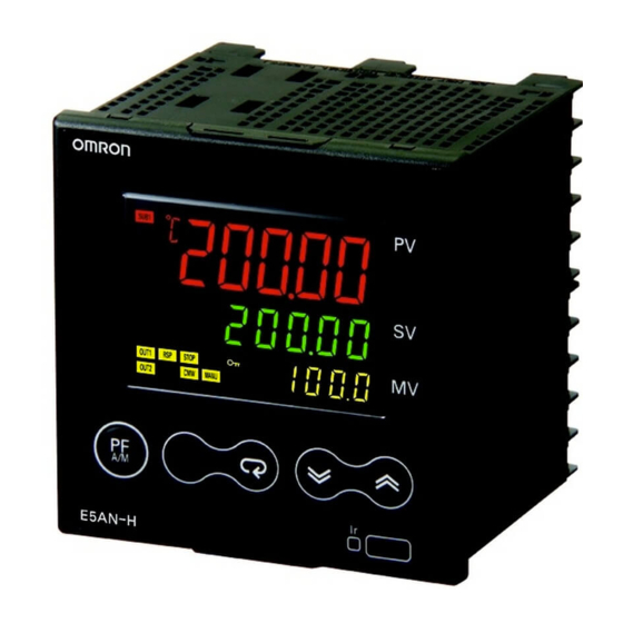
Names of Parts Section 1-1 Names of Parts 1-1-1 Front Panel E5CN-H Temperature unit No. 1 display Operation indicators No. 2 display Level Key Up Key Mode Key Down Key E5AN-H Temperature unit No. 1 display Operation indicators No. 2 display No. -
Page 24: Explanation Of Indicators
Displays the process value or parameter name. Lights for approximately one second during startup. No. 2 Display Displays the set point, parameter operation read value, or the variable input value. Lights for approximately one second during startup. No. 3 Display Displays MV (valve opening), soak time remain, or bank number. -
Page 25: Using The Keys
This section describes the basic functions of the front panel keys. PF (Function (Auto/ This is a function key. When it is pressed for at least 1 second, the function set Manual)) Key in the PF Setting parameter will operate. -
Page 26: I/O Configuration And Main Functions
O + D Keys ations), these key operations require simultaneously pressing the O key along with U or D key. This applies only to the parameter for the password to move to protect level. (Refer to page 174.) I/O Configuration and Main Functions... - Page 27 CN: E5CN-H or E5CN 2. Control Output 1 2. Function 1 R: Relay output Blank: None Q: Voltage output Control output 2 (voltage output for (for driving SSR) driving SSR) C: Current output Power supply for sensor V: Linear voltage output Current output 3.
- Page 28 Communications function Note Functions can be assigned individually to each output by changing the set val- ues for the Control Output 1 Assignment, Control Output 2 Assignment, Auxil- iary Output 1 Assignment, Auxiliary Output 2 Assignment, and Auxiliary Output 3 Assignment parameters in the advanced function setting level.
-
Page 29: Main Functions
1-2-2 Main Functions This section introduces the main E5@N-H functions. For details on particular functions and how to use them, refer to SECTION 3 Basic Operation and fol- lowing sections. Input Sensor Types • The following input sensors can be connected.:... - Page 30 Therefore, use auxiliary output 1 if an auxiliary output is required while using heating/cooling control. Alarms • Set the alarm type and alarm value or the alarm value upper and lower limits. • If necessary, a more comprehensive alarm function can be achieved by setting a standby sequence, alarm hysteresis, auxiliary output close in alarm/open in alarm, alarm latch, alarm ON delay, and alarm OFF delay.
- Page 31 I/O Configuration and Main Functions (4) The E5CN-H does not support the RS-422 interface. Transfer Output A 4 to 20-mA transfer output can be used with the E53-CN@FN2 for the E5CN-H, or the E5AN/EN-H@@F-500. Remote SP Inputs Remote SP inputs can be used with the E5AN-H and E5EN-H.
-
Page 32: Setting Level Configuration And Key Operations
Note (1) Your can return to the operation level by executing a software reset. (2) You cannot move to other levels by operating the keys on the front panel from the calibration level. You must turn OFF the power supply. - Page 33 • To switch to the protect level from the operation level, the adjustment level, bank setting level, or PID setting level, simultaneously hold down the O and M Keys for at least 3 seconds. (See note.) This level is for pre- venting unwanted or accidental modification of parameters. Protected lev- els will not be displayed, and so the parameters in that level cannot be modified.
- Page 34 • This is the level for changing the MV in manual mode. • To return to the operation level, press the O Key for at least one second. It is also possible to return to the operation level by pressing the PF Key for more than one second when the PF Setting is set to A-M.
-
Page 35: Communications Function
Parameter 4 1-3-2 Saving Settings • If you press the M Key at the final parameter, the display returns to the top parameter for the current level. • To change parameter settings, specify the setting using the U or D Key, and either leave the setting for at least two seconds or press the M Key. - Page 36 Section 1-4 Communications Function 2. Press the O Key for less than one second to move from the initial setting level to the communications setting level. 3. Select the parameters as shown below by pressing the M Key. 4. Press the U or D Key to change the parameter setting.
- Page 37 Section 1-4 Communications Function...
-
Page 38: Preparations
Wiring ..........Using the Support Software Port........ -
Page 39: Installation
Section 2-1 Installation Installation 2-1-1 Dimensions Unit: mm E5CN-H 48 × 48 E5AN-H 79.2 E5EN-H 79.2... -
Page 40: Panel Cutout
(96 × number of Units − 3.5) +1.0 Note Group mounting is not possible when an SSR output is used for control output 1 or 2 and an E53-C3N or E53-C3DN Output Unit is used. Mount at the intervals shown in the following diagram. - Page 41 60 min. • Waterproofing is not possible when group mounting several Controllers. • The recommended panel thickness is 1 to 5 mm for E5CN-H, and 1 to 8 mm for E5AN/E5EN-H. • Units must not be group mounted vertically. In addition, group mounting is not possible when an SSR output is used for control output 1 or 2 and an E53-C3N or E53-C3DN Output Unit is used.
- Page 42 2. Insert the E5CN-H into the mounting hole in the panel. 3. Push the adapter from the terminals up to the panel, and temporarily fasten the E5CN-H. 4. Tighten the two fastening screws on the adapter. Alternately tighten the two screws little by little to maintain a balance.
- Page 43 Installation Section 2-1 Mounting the Terminal Cover Make sure that the "UP" mark is facing up, and then attach the E53-COV17 Terminal Cover to the holes on the top and bottom of the Digital Controller. E5AN/EN-H Mounting Bracket Panel Terminal Cover...
- Page 44 2-1-4 Removing the Digital Controller from the Case The body of the Digital Controller can be removed from the case to set Output Units or to perform maintenance. Check the specifications of the case and Digital Controller before removing the Digital Controller from the case.
- Page 45 2. Insert the flat-blade screwdriver in the gap between the front panel and rear case, and pull out the front panel slightly. Hold the top and bottom of the front panel and carefully pull it out toward you, without applying unnec- essary force.
- Page 46 2. Insert a flat-blade screwdriver in the gap between the front panel and rear case (two on the top and two on the bottom), and use it to pry and pull out the front panel slightly. Then, pull out on the front panel gripping both sides.
- Page 47 E5AN/EN-H toward the rear case until it snaps into position. While pressing the E5AN/EN-H into place, press down on the hooks on the top and bottom surfaces of the rear case so that the hooks securely lock in place. Make sure that electronic components do not come into contact with the case.
- Page 48 Hooks securing PCB Hooks securing PCB E5AN-H E5EN-H 2. Set the Output Unit for control output 1 in the OUT1 socket. Set the Output Unit for control output 2 in the OUT2 socket. OUT1 OUT2 3. For the E5AN-H, use the enclosed clamps to secure the Output Units. Do not use clamps for the E5EN-H.
-
Page 49: Wiring Terminals
Section 2-2 Wiring Terminals Wiring Terminals Check the terminal arrangements for E5CN-H terminals 1 to 15 and E5AN/ EN-H terminals 1 to 30 as marked on the product label and on the side of the case. 2-2-1 Terminal Arrangement E5CN-H... - Page 50 4 to 20 mA DC Auxiliary output 1 Auxiliary output 1 Auxiliary output 1 Remote SP input 250 VAC, 3 A (resistive load) Note Wire all voltage input terminals correctly. The Controller may fail if voltage input terminals are wired incorrectly.
-
Page 51: Precautions When Wiring
• Use the following types of crimp terminals for M3.5 screws. 7.2 mm max. 7.2 mm max. Note Do not remove the terminal block. Doing so will result in malfunction or failure. 2-2-3 Wiring In the connection diagrams, the left side of the terminal numbers represents the inside of the Controller and the right side represents the outside. - Page 52 Section 2-2 Wiring Terminals Control Output 1 • Outputs are sent from terminals 1 and 2 with the E5CN-H and from pins 3 and 4 with the E5AN/EN-H. The following diagrams show the available outputs and their internal equalizing circuits.
- Page 53 • The E5CN-H voltage output (for driving SSR) is not electrically isolated from the internal circuits. When using a grounding thermocouple, do not connect any of the control output terminals to the ground. (If a control out- put terminal is connected to the ground, errors will occur in the measured temperature as a result of leakage current.) E5AN/EN-H voltage outputs...
- Page 54 440 to 470 V Control Output 2 • Outputs are sent from terminals 11, 12, 14, and 15 with the E5CN-H, and from pins 5 and 6 with the E5AN/EN-H. The following diagrams show the available outputs and their internal equalizing circuits.
- Page 55 (for driving SSR), however, are functionally isolated from the internal cir- cuits. • Control output 2 of the E5CN-H is a voltage output (for driving SSR) only, and outputs across terminals 11(+) and 12(-), or 14(+) and 15(-). • Control output 1 (voltage output for driving SSR) and control output 2 (voltage output for driving SSR) are not isolated.
- Page 56 HB alarm, HS alarm, or heater overcurrent alarm is output. If the alarm 1 function is to be used for HB alarm only, set the alarm 1 type to 0 (i.e., do not use alarm 1 function).
- Page 57 SUB2 SUB1 SUB1 E5AN/EN-H E5CN-H ALM1, 2, 3 can be output to auxiliary output 1, 2, 3 or changed with the advanced function setting level. • The relay specifications are as follows: E5@N-H (SUB1, SUB2) SPST-NO, 250 VAC, 3 A...
- Page 58 Even with models that do not have a transfer output, control outputs 1 or 2 can be used as a simple transfer output if it is a current output or linear output. For details on the operation, refer to 4-14 Using the Transfer Output.
- Page 59 Terminator (120 Ω, 1/2 W) • The RS-485 connection can be either one-to-one or one-to-N. A maxi- mum of 32 Units (including the host computer) can be connected in one- to-N systems. The maximum total cable length is 500 m. Use AWG24 (cross-sectional area: 0.205 mm...
- Page 60 RS (RTS) ER (DTR) CS (CTS) • A 1:1 connection is used. The maximum cable length is 15 m. To extend the transmission path, use the OMRON Z3R RS-232C Optical Interface. • Use AWG24 (cross-sectional area: 0.205 mm ) to AWG14 (cross-sec- tional area: 2.081 mm...
-
Page 61: Using The Support Software Port
(240 Ω, 1/2 W) Shielded cable • A 1:1 or 1:N connection is used. When a 1:N connection is used, a maxi- mum of 32 nodes including the host computer can be connected. • Use AWG24 (cross-sectional area: 0.205 mm ) to AWG14 (cross-sec- tional area: 2.081 mm... - Page 62 • Installation When the Cable is connected with the personal computer, the OS detects the product as a new device. At this time, install the driver using the instal- lation wizard. For details on installation methods, refer to the user’s man- ual for the E58-CIFQ1 USB-Serial Conversion Cable.
-
Page 63: Using Infrared Communications
• Installation When the Cable is connected with the personal computer, the OS will detect is as a new device. At this time, install the driver using the installa- tion wizard. For details on installation methods, refer to the Instruction Sheet and Setup Manual for the E58-CIFIR USB-Infrared Conversion Cable. - Page 64 Setup Manual for details on checking the COM port assigned to the USB-Infrared Conversion Cable. The communications conditions for infra- red COM ports are fixed as shown in the table below. Set the communica- tions conditions for the CX-Thermo Setup Tool according to the following table.
- Page 65 Using Infrared Communications Section 2-4...
-
Page 66: Basic Operation
Setting Output Specifications ........ -
Page 67: Initial Setting Examples
Initial hardware setup, including the sensor input type, alarm types, control periods, and other settings is done using parameter displays. The O and M Keys are used to switch between parameters, and the amount of time that you press the keys determines which parameter you move to. - Page 68 Set alarm type Check the Control Period It is recommended that 20 seconds control period. (Heat) be set for a relay output and 2 (Unit: Seconds) seconds for an SSR voltage output. Check the alt1 alarm type. Alarm 1 Type: Press the O key for at least 1 s.
- Page 69 5 (K thermocouple, −200.0°C to 1,300.0°C) Control method: Floating control (default) SP ramp time unit: EU/min (default) Travel time: 45 s SP ramp set value: 10.0 EU (°C) Set point: 250°C Setup Procedure Power ON Power ON Operation Level 25.0...
-
Page 70: Setting The Input Type
The following example shows how to set a K thermocouple for −20.0 to 500.0°C. Operating Procedure 1. Press the O Key for at least three seconds to move from the operation Operation Level level to the initial setting level. 25.0 2. - Page 71 • If a platinum resistance thermometer is mistakenly connected while a set- ting for other than a platinum resistance thermometer is in effect, S.ERR will be displayed. To clear the S.ERR display, check the wiring and then turn the power OFF and back ON.
-
Page 72: Selecting The Temperature Unit
Input Type in-t c: °C f: °F 3. To return to the operation level, press the O Key for at least one second. Temperature Unit Selecting PID Control or ON/OFF Control Two control methods are supported: 2-PID control and ON/OFF control. -
Page 73: Setting Output Specifications
Control Period better control performance, it is recommended that the control period be (Heating) set to 20 seconds or longer for a relay output to preserve the service life Control Period c-cp of the relay. After the settings have been made in the initial setup, readjust (Cooling) the control period, as required, by means such as trial operation. -
Page 74: Assigned Output Functions
30.0 Initial Setting Level 2. The input type is displayed. When the input type is being set for the first time, s (K thermocouple) is set. To select a different sensor, press the U Input Type in-t or D Key. - Page 75 Control Output 1 Assignment parameter, then alarm 1 has been assigned. Assigning a work bit to either control output 1 or 2 or to auxiliary output 1 to 3 is also considered to be the same as assigning an alarm. For example, if work bit 1 is set for the Auxiliary Output 1 Assignment parameter, then alarms 1 to 3 have been assigned.
- Page 76 M Key. (For details on moving between levels, refer to 4-8 Moving vanced Function Setting Level to the Advanced Function Setting Level.) 5. Press the D Key to enter the password (“−169”), and move from the initial Advanced Function Setting Level setting level to the advanced function setting level. Parameter...
-
Page 77: Setting The Set Point (Sp)
Setting the Set Point (SP) Operation Level The operation level is displayed when the power is turned ON. The process value (PV) is at the top of the display, and the set point (SP) is at the bottom. 20.0 Operation Level For Controllers that support a No. -
Page 78: Using On/Off Control
• Switching between 2-PID control and ON/OFF control is performed using the PID ON/OFF parameter in the initial setting level. When this parame- ter is set to pid, 2-PID control is selected, and when it is set to onof, ON/ OFF control is selected. The default is pid. -
Page 79: Settings
Three-position • In heating/cooling control, a dead band (an area where both control out- Control puts are 0) can be set to either the heating or cooling side. This makes it possible to use 3-position control. Reverse operation Dead band... - Page 80 PV/SP 25.0 100.0 2. Use the U and D Keys to set the SP. (In this example, it is set to 200.0.) 25.0 The new set value can be saved by pressing the M Key, or it will go into effect after two seconds have elapsed.
-
Page 81: Determining Pid Constants (At, St, Manual Setup)
• Either 40% AT or 100% AT can be selected depending on the width of MV variation in the limit cycle. In the AT Execute/Cancel parameter, specify at-2 (100% AT) or at-1 (40% AT). - Page 82 ■ 40% AT The width of MV variation in the limit cycle can be changed in the Limit Cycle MV Amplitude parameter, but the AT execution time may be longer than for 100% AT. The limit cycle timing varies according to whether the deviation (DV) at the start of auto-tuning execution is less than 10% FS.
-
Page 83: St (Self-Tuning)
ST (self-tuning) is enabled when the ST parameter is set to ON in the initial setting level. When the ST function is in operation, be sure to turn the power supply of the load connected to the control output ON simultaneously with or before starting Controller operation. - Page 84 2. When auto-tuning (AT) has been executed. 3. When the PID set has been changed during SRT. 4. When the PID set for the current bank is set to 0 (PID set automatic selec- tion). In addition, the following diagrams show the difference between setting a dif- ferent PID set for each bank and setting the same PID set.
-
Page 85: Rt (Robust Tuning)
• When the RT mode is selected, the derivative time setting unit be- comes the second. RT Features • Even when hunting occurs for PID constants when AT or ST is executed in normal mode, it is less likely to occur when AT or ST is executed in RT mode. - Page 86 Start of control Start of control • When the temperature (PV) falls short of the set point for the PID con- stants when using AT or ST in normal mode, executing AT or ST in RT mode tends to improve performance.
-
Page 87: Manual Setup
Determining PID Constants (AT, ST, Manual Setup) 5. Press the U Key to select on. off is the default. 6. To return to the initial setting level, press the O Key for at least one sec- Initial Setting Level ond. -
Page 88: Alarm Outputs
9. To return to the operation level, press the O Key. Note Proportional Action When PID constants I (integral time) and D (derivative time) are set to 0, con- trol is executed according to proportional action. As the default, the center value of the proportional band becomes the set point. - Page 89 (See note 6.) Note (1) With set values 1, 4, and 5, the upper- and lower-limit values can be set independently for each alarm type, and are expressed as “L” and “H.” (2) Set value: 1 (Upper- and lower-limit alarm)
-
Page 90: Alarm Values
: 0 to 7) • To set the alarm upper and lower limits for deviation, set the upper and .a2l lower limits in the Alarm 1 to 3 Upper Limit and Alarm 1 to 3 Lower Limit ∗ parameters. .a3l •... - Page 91 60 ms. If a positive value is set for the alarm value, the PV will operate as a change rate alarm in the rising direction. If a negative value is set, the PV will operate as a change rate alarm in the falling direction.
-
Page 92: Using Heater Burnout, Heater Short, And Heater Overcurrent Alarms
Control output (heating) Note (1) In the above diagram, power is considered to be ON (normal) if the heater current is greater than the heater burnout detection current during the Ton interval. If the heater is burned out, the measured current decreases and falls below the heater burnout detection value. -
Page 93: Installing Current Transformers (Ct)
1.0 A for heaters of less than 10.0 A, and at least 2.5 A for heaters of 10.0 A or more. If the heater current is too low, loop the load line several times through a CT, as shown in the diagram below. -
Page 94: Calculating Detection Current Values
Heater Burnout Detection 1/2 set value = Normal current value + Burnout current value HS Alarm 1/2 set value = Leakage current value (output OFF) + HS current value Heater overcurrent 1/2 set value = Normal current value + Overcurrent value •... -
Page 95: Application Examples
When the difference is less than 2.5 A, detection is unstable. • The setting range is 0.1 to 49.9 A. Heater burnout, HS, and heater over- current are not detected when the set value is 0.0 or 50.0. When the set value is 0.0, the heater burnout alarm is always OFF, the HS alarm is... - Page 96 Current when there is a burnout = 10 A × √3 × (√3/2) = 15 A (1/√3) = 10 A The heater burnout current when there is a burnout at the load line is as fol- lows: (Heater burnout detection current) = (17.3 + 15) / 2 ≈ 16.1 [A] The heater burnout current when there is a burnout at the load is as follows: (Heater burnout detection current) = (17.3 + 10) / 2 ≈...
- Page 97 Product To CT input 5.8 A→ Product To CT input The current when each phase is normal is 5.8 A (≈ 10 A × (1 /√3)). Burnout Burnout 5 A→ Load (such as a heater) Load (such as a heater)
- Page 98 Current when there is a burnout = 0 A = 5 A The heater burnout current when there is a burnout at the common is as fol- lows: Heater burnout detection current = (10 + 5) / 2 ≈ 7.5 [A] The heater burnout current when there is a burnout at the load is as follows: Heater burnout detection current = (10 + 0) / 2 ≈...
-
Page 99: Settings: Hb Alarm
(For details on moving between levels, refer to 4-8 Moving to the Ad- Input Type in-t vanced Function Setting Level.) 3. Press the D Key to enter the password (−169), and move from the initial Initial Setting Level setting level to the advanced function setting level. Moves to Ad-... -
Page 100: Settings: Heater Short Alarm
Section 3-10 Using Heater Burnout, Heater Short, and Heater Overcurrent Alarms 9. For this example, set 2.5. To return to the operation level, press the O Key for less than one second. 3-10-6 Settings: Heater Short Alarm To activate the HS alarm, set the HS Alarm Use parameter to ON in the advanced function setting level and set the HS Alarm 1 and HS Alarm 2 parameters in the adjustment level. -
Page 101: Settings: Heater Overcurrent Alarm
Using Heater Burnout, Heater Short, and Heater Overcurrent Alarms ■ HS Alarm Settings 5. Press the O Key for at least one second to move from the advanced Operation Level function setting level to the initial setting level. Press the O key again for PV/SP 25.0... - Page 102 Heater Overcurrent Detection 1 parameter. ■ Setting Heater Overcurrent Detection 5. Press the O Key for at least one second to move from the advanced Operation Level function setting level to the initial setting level. Press the O key again for PV/SP 25.0...
-
Page 103: Setting The No. 3 Display
Display for Heating and Cooling Control below. The MV for position-pro- portional models becomes the value for opening the valve. When 1, 2, 5, or 6 is selected, press the M Key to display the next value set for the PV/SP display (display 2). - Page 104 Input Type in-t The MV will be displayed on the No. 3 display. 8. Press the M Key to confirm that the Bank No. is displayed on the No. 3 Operation Level PV/SP 25.0 100.0 50.0...
- Page 105 Section 3-11 Setting the No. 3 Display...
-
Page 106: Applications Operations
Standby Sequence........ - Page 107 4-19 Setting the Width of MV Variation ....... . .
-
Page 108: Shifting Input Values
4-1-1 Shifting Inputs Either a 1-point shift or a 2-point shift can be used to shift the input. The default setting is for a 1-point shift. To execute a 2-point shift, change the Input Shift Type parameter setting (advanced function setting level) to INS2. -
Page 109: How To Calculate Input Shift Values For A 2-Point Shift
Section 4-1 Shifting Input Values Two-point shift • Separate shift values can be set for the upper limit and lower limit of the Upper-limit insh sensor input range for an infrared sensor as well as for a thermocouple or Temperature... - Page 110 (e.g., 120°C) (A) E5@N-H Figure 2 Illustration of 1-Point Shift Method for a 2-point Use a 2-point input shift if you want to increase the accuracy of the readout Shift values across the range of the Sensor. 1,2,3... 1. Shift the Controller readout at two points, near room temperature and near the value at which the temperature of the control target is to be controlled.
-
Page 111: Alarm Hysteresis
Example of a 2-point In this example, a K thermocouple from −200.0 to 1,300.0°C is used. In equa- tions 1 and 2, the set temperature lower limit YL is −200°C and the set tem- Temperature Input Shift perature upper limit YH is 1,300°C. -
Page 112: Alarm Latch
4-2-2 Alarm Latch • The alarm latch can be used to keep the alarm output ON until the latch is canceled regardless of the temperature once the alarm output has turned Any of the following methods can be used to clear the alarm latch. -
Page 113: Setting Scaling Upper And Lower Limits For Analog Inputs
Lower limit (10.0%) Input (mA) Operating Procedure In this example scaling is set to display 4 to 20 mA as 10.0% to 95.0%. 1. Press the O Key for three seconds to move from the operation level to Initial Setting Level the initial setting level. -
Page 114: Executing Heating/Cooling Control
7. Select the Decimal Point parameter by pressing the M Key. Decimal Point 8. Press the U and D Keys to set 1. 9. To return to the operation level, press the O Key for one second. Executing Heating/Cooling Control 4-4-1... - Page 115 • If an overlapping band is set, the bumpless function may not operate when switching between manual operation and automatic operation. • The default is 0.0 EU for a temperature input and 0.00% FS for an analog input. Dead band: Dead band...
-
Page 116: Settings
Operating Procedure PID 1 Cooling Coefficient = 10 1. Press the O Key to move from the operation level to the PID setting level. PID Setting Level The current PID set number will be displayed. Use the U or D Key to Display PID d.pid... -
Page 117: Using Event Inputs
• Depending on the Controller, there are either two event inputs (event inputs 1 and 2 or 3 and 4) or four event inputs (event inputs 1 to 4). The number of event inputs that can be used varies. (Only the E5AN/EN-H has event inputs 3 and 4.) - Page 118 • Switching is possible between two banks (0 and 1) by setting the Bank Numbers Used parameter to 1. The default setting is 1 and does not need to be changed. Banks 0 and 1 are specified by the status of event input 1 or 3.
-
Page 119: Operation Commands Other Than Bank Selection
ON/OFF changes are detected for inputs of 50 ms or longer. (However, inputs of 250 ms or longer is determined using logic operation.) The functions are described in detail below. Event inputs 1 and 2 are taken as examples. When using event inputs 3 and 4, substitute event input 3 for event input 1 and event input 4 for event input 2. - Page 120 When the Event Input Assignment 1 or Event Input Assignment 2 parameter of the Simple is set to PRST (program start), the program will start when event input 1 or 2 turns ON. The program will be reset when the input turns OFF and the RUN/ Program Function STOP status will automatically switch to STOP mode.
-
Page 121: Setting The Sp Upper And Lower Limit Values
When WTPT (Setting Change Enable/Disable) is set for either the Event Input Change Enable/ Assignment 1 or Event Input Assignment 2 parameter, the setting change will be disabled when event input 1 or 2 turns ON and will be enabled when the Disable input turns OFF. -
Page 122: Setting
4-6-2 Setting Set the set point upper and lower limits in the Set Point Upper Limit and Set Point Lower Limit parameters in the initial setting level. In this example, it is assumed that the input type is set to a K thermocouple with a temperature range of −200.0 to 1300.0°C. -
Page 123: Using The Sp Ramp Function To Limit The Sp Change Rate
During the SP ramp, control will be performed not for the specified set point but rather for the set point restricted by the rate of change set for the SP ramp function. - Page 124 STOP to RUN mode, the process value reaches the set point using the SP ramp function in the same way as when the set point is changed. In this case, operation is carried out with the process value treated as the set point before the change was made.
-
Page 125: Moving To The Advanced Function Setting Level
The operation of alarms during SP ramp operation depends on whether Ramp Operation alarms are set to be based on the ramp set point or the target set point (refer to the following diagrams). The set point to be used is set in the Alarm SP Selection parameter. - Page 126 M Key or leave the setting for at least two seconds to move to the ad- Parameter init vanced function setting level from the initial setting level. Initialization 9. To return to the initial setting level, press the O Key for at least one sec- Initial Setting Level ond. Input Type in-t 10.
-
Page 127: Using The Key Protect Level
4-9-1 Protection • To move to the protect level, press the O and M Keys simultaneously for at least three seconds in operation level or adjustment level. (See note.) Note The key pressing time can be changed in the Move to Protect Level Time parameter (advanced function setting level). -
Page 128: Entering The Password To Move To The Protect Level
■ Example with a Password of 1234 Operation Level PV/SP 25.0 100.0 1. Press the O and M Keys simultaneously for at least the time set in the Protect Level Move to Protect Level Time parameter to move from the operation level Move to Protect pmov to the protect level. - Page 129 Write Variable operation commands to write parameters in the protect level will result in operation errors. (2) If a password is not set or if it is set to 0, the display will change to the Operation/Adjustment Protect parameter and writing the parameters in...
-
Page 130: Pv Change Color
PV Change Color 4-10 PV Change Color 4-10-1 PV Color Change Function Use the PV color change function to change the color of the PV display (No. 1 display). There are three display colors, orange, red, and green, and you can select from the following three modes and eight functions. -
Page 131: Setting
Section 4-10 PV Change Color PV Stable Band When the mode to link to the PV stable band is selected, the PV display color will change according to whether the present value (PV) is lower than, within, PV Stable pv-b Band or higher than the PV stable band shown in the following figure. - Page 132 7. Use the U Key to set the parameter to 15.0. pv-b 15.0 8. To return to the initial setting level, press the O Key for at least one sec- ond. 9. To return to the operation level, press the O Key for at least one second.
-
Page 133: Alarm Delays
Alarm will not turn ON. • The alarm will not turn ON if the time that the alarm is ON is equal to or less than the ON delay set time. Also, the alarm will not turn OFF if the time that the alarm is OFF is equal to or less than the OFF delay set time. - Page 134 (1) The defaults are 0, i.e., the ON and OFF delays are disabled. (2) The parameters are displayed when alarm functions are assigned and when the alarm type is set to any type but 0 (none), 12: LBA, or 13: PV change rate alarm.
-
Page 135: Loop Burnout Alarm
Loop Burnout Alarm Section 4-12 9. Press the O Key for at least one second to move from the initial setting Operation Level level to the operation level. PV/SP 25.0 100.0 4-12 Loop Burnout Alarm 4-12-1 Loop Burnout Alarm (LBA) •... - Page 136 LBA level, preventing detection of the loop burnout. • If the set point is so high or low that it cannot be reached even with a sat- urated manipulated variable, a temperature deviation may remain even in a steady state and a loop burnout may be detected.
- Page 137 Operating Procedure Perform the following procedure to use the loop burnout alarm. In this example, the LBA detection time is set to 10, the LBA level is set to 8.0, and the LBA band is set to 3.0. Operation Level PV/SP 25.0...
- Page 138 12. Press the U Key to set the parameter to 8.0. (The default is 8.0.) lbal 13. Select the LBA Band parameter by pressing the M Key. Advanced Function Setting Level LBA Band lbab 14. Press the U or D Key to set the parameter to 3.0. (The default is 3.0.) lbab...
- Page 139 12. Press the U Key to set the parameter to 8.0. (The default is 8.0.) LBA Band lbab 13. Select the LBA Band parameter by pressing the M Key. Advanced Function Setting Level lbab 14. Press the U or D Key to set the parameter to 3.0. (The default is 3.0.)
-
Page 140: Performing Manual Control
15. Press the O Key for at least one second to move from the advanced Initial Setting Level function setting level to the initial setting level. Input Type in-t 16. Press the O Key for at least one second to move from the initial setting Operation Level level to the operation level. PV/SP 25.0 100.0... - Page 141 • Switching between manual and automatic operation is possible for a maximum of one million times. • When close control is used or when the Direct Setting of Position Propor- tional MV parameter is set to ON: • Just as with standard models, the MV is set numerically.
-
Page 142: Manual Control Level
OFF: Disabled, ON: Enabled Enable Moving from the • When the O Key is pressed for at least 3 seconds in the operation level's Operation Level to the auto/manual switching display, the manual mode will be entered and the manual control level will be displayed. It is not possible to move to any dis- Manual Control Level plays except for the PV/MV parameter during manual operation. - Page 143 Use the following procedure to set the manipulated variable in manual mode. Operation Level PV/SP 25.0 100.0 1. Press the O Key for at least three seconds to move from the operation Initial Setting Level level to the initial setting level. Input Type in-t 2.
- Page 144 10. Press the O Key for at least three seconds to move from the operation Manual Control Level level to the manual control level. PV/MV 25.0 11. Press the U or D Key to set the manual MV. (In this example, the MV is 25.0 set to 500%.) 50.0 Note...
-
Page 145: Using The Transfer Output
10. Press the PF Key for at least one second to move from the operation level to the manual control level. PV/MV 25.0 11. Press the U or D Key to set the manual MV. (In this example, the MV is 25.0 set to 50.0%.) 50.0... - Page 146 Using the Transfer Output • The operation differs for models with a transfer output and models without a transfer output for which control output 1 or control output 2 is used as a simple transfer output, as shown in the following table.
- Page 147 Control output MV (%) (The above graph is for when the linear current output is set to 4 to 20 mA.) (3) When the set point is selected, remote SP will be output while the Remote SP Mode is set in the SP Mode parameter.
- Page 148 Transfer output lower limit upper limit (The above graph is for when the linear current output is set to 4 to 20 mA.) The following procedure sets the transfer output for an SP range of −50 to Operating Procedure 200.
- Page 149 Using the Transfer Output 7. Use the U Key to set the parameter to −50.0. The default is −200.0. tr-l -50.0 8. To return to the operation level, press the O Key for at least one second. Operation Level PV/SP 25.0...
-
Page 150: Using Banks And Pid Sets
If the following parameters are changed, the changes will be saved in the cur- rent bank: Set Point, Alarm Values 1 to 3, Alarm Value Upper Limits 1 to 3, Alarm Val- ue Lower Limits 1 to 3, (operation level) SP Ramp Set Value, Soak Time, Wait Band (adjustment level). - Page 151 LBA Detection Time (advanced function setting level) Automatic PID Set Selection • If the PID Set No. parameter for a bank is set to 0, the PID set will be selected automatically according to preset conditions. In the setting example on the left (with the PID Set Automatic Selection Data parame-...
- Page 152 PID Set Automatic PV: Process value None Setting Data DV: Derivative value SP: Set point PID Set Automatic 0.10 to 99.99 0.50 Hysteresis Note When the PID Set Automatic Hysteresis parameter is set to DV, the default setting becomes %FS.
-
Page 153: Using The Simple Program Function
The program can be created from the required number of banks by speci- fying the end bank in the Valid Program Bank parameter. A simple program can be started from any of the banks from bank 0 to the end bank. When operation is finished in one bank, the program switches to the next bank and operation starts in that bank. - Page 154 0 and the program execution will continue. • Banks where the Soak Time parameter is set to 0 will not be executed. • The bank number can be changed even during program operation by using either an event input or key operations.
- Page 155 Note When an event input is used to start and reset the simple program, writing is performed to EEPROM. Be sure to consider the write life (1 million writes) of the EEPROM in the system design. When the program start is assigned to an...
- Page 156 (i.e., SP ± wait band). In the following dia- gram, the timer will be stopped between the start and (1), (2) and (3), and (4) and (5) and will measure the time only between (1) and (2), (3) and (4), and (5) and the end.
-
Page 157: Operation At The Program End
Section 4-16 Using the Simple Program Function Note If the wait band is set to OFF, the wait band will be treated as infinity and the timer will measure time continuously after changing from RSET to STRT. Operation When The following will occur if a power interruption occurs during execution of a... -
Page 158: Combining A Simple Program With An Sp Ramp
Bank n Bank n+1 If the program moves to the next bank at the end of the soak time before the ramp SP reaches the SP, the SP ramp operation will extend across the banks as shown below as long as the SP Ramp Set Value parameter is not set to 0. -
Page 159: Relationships Between Simple Programs And Other Functions
Using the Simple Program Function SP Start Program operation can be started by using an SP start from the bank 0 LSP. To use an SP start, set the SP Ramp Set Value and Soak Time parameters for bank 0 to 0. Example... - Page 160 • Changing Banks If the bank is changed while the simple program is being executed, the time up to that point will be cleared and timing will start for the new bank's set value. Operating Procedure Perform the following procedure to use the simple program function.
- Page 161 5. Use the U and D Keys to set 2. pbnk 6. Press the O Key for at least one second to move from the initial setting pbnk level to the operation level. 7. Press the O Key to move from the operation level to the bank setting lev-...
-
Page 162: Output Adjustment Functions
0.sok 22. Use the U and D Keys to set the parameter to 5.0. Bank 1 1.wtb Wait band 23. Press the O Key to move from the bank setting level to the operation lev- 1.wtb Operation Level PV/SP 25.0 100.0... -
Page 163: Mv At Stop
For heating/cooling control, the MV at stop will apply to the cooling side if the MV is negative and to the heating side if the MV is positive. The default is 0.0, so an MV will not be output for either standard or heating/cooling control. -
Page 164: Mv At Pv Error
OPEN (Control output 1 ON) Note The order of priority is as follows: Manual MV > MV at stop > MV at PV error. • The following table shows the operation when a potentiometer error occurs when the Direct Setting of Position Proportional MV parameter is set to ON. -
Page 165: Using The Extraction Of Square Root Parameter
OPEN (Control output 1 ON) Note The order of priority is as follows: Manual MV > MV at stop > MV at PV error. • The following table shows the operation when a potentiometer error occurs when the Direct Setting of Position Proportional MV parameter is set to ON. - Page 166 Input Type in-t 2. Use the U and D Keys to set the parameter to 25 (4 to 20 mA). in-t 3. Press the M Key to select the Extraction of Square Root Enable param- Extraction eter.
-
Page 167: Setting The Width Of Mv Variation
Section 4-19 Setting the Width of MV Variation 5. Press the O Key for at least one second to move from the initial setting Operation Level level to the operation level. PV/SP 25.0 100.0 6. Press the O Key to move from the operation level to the adjustment level. - Page 168 4. Press the M Key to select the ST parameter. 5. Press the D Key to select OFF. 6. Press the O Key for at least one second to move from the initial setting Operation Level level to the operation level.
-
Page 169: Setting The Pf Key
Setting the PF Key 4-20 Setting the PF Key 4-20-1 PF Setting (Function Key) PF Setting • Pressing the PF Key for at least one second executes the operation set in the PF Setting parameter (E5AN/EN-H only). Set value Symbol... - Page 170 (2) While a monitor/setting item is being displayed, the display will be switched to the top parameter in the operation level if the M Key or the O Key is pressed.
-
Page 171: Counting Control Output On/Off Operations
Function Setting Level -169 3. Press the D Key to enter the password (−169). It is possible to move to Advanced Function Setting Level the advanced function setting level by either pressing the M Key or wait- Parameter init ing two seconds without pressing any key. - Page 172 OFF Count Alarm value, an ON/OFF count alarm will occur. The alarm status can be assigned to a control output or an auxiliary output, or it can be displayed at the Control- Function ler. The ON/OFF count alarm set value function is disabled by setting the ON/ OFF count alarm set value to 0.
-
Page 173: Displaying Pv/Sv Status
Control Output 1 ON/OFF Count Alarm Set Value 6. Press the O Key for at least one second to move to the initial setting lev- Initial Setting Level Input Type in-t 7. Press the O Key for at least one second to move to the operation level. - Page 174 100.0 25.0 SV Status Display The SP, Blank, or Manual MV in the PV/SP, PV, or PV/Manual MV Display Function (Valve Opening) and the control and alarm status specified for the SV status display function are alternately displayed in 0.5-s cycles.
- Page 175 Function Setting Level -169 3. Use the D Key to enter the password (−169). It is possible to move to the Advanced Function Setting Level advanced function setting level by either pressing the M Key or waiting Parameter init two seconds without pressing any key.
-
Page 176: Using A Remote Sp
Remote SP Upper Limit and Remote SP Lower Limit parameter settings. • The remote SP input can be input in a range of −10% to 110% of 4 to 20 mA. Input values outside of this range treated as out-of-range input val- ues (RSP input error) and clamped to the upper or lower limit. - Page 177 SP is selected in SP mode, the RSP single indicator will light. Remote SP Monitor In remote SP mode, the remote SP can be checked on the No. 2 display in the PV/SP Display Screen. In local SP mode, it can be checked with the Remote SP Monitor parameter.
-
Page 178: Position-Proportional Control
Position-proportional Control 4-24 Position-proportional Control The control method used to adjust the opening and closing of a valve with a control motor is called "position-proportional control" or "ON/OFF servo con- trol." Either closed control or floating control can be selected for position-pro- portional control. - Page 179 When the process value (PV) is within the PV dead band, control is executed as if the process value is equal to the set point for the current bank to prevent unnecessary outputs when the process value is in the vicinity of the set point.
-
Page 180: Logic Operations
Up and Down Keys. The output on the open side is ON while the Up Key is pressed, and the output on the closed side is ON while the Down Key is pressed. If the Direct... - Page 181 1,2,3... 1. Displaying the Library Import Dialog Box Logic operation samples for specific cases are set in the library in advance. Examples of settings for specific cases are loaded by selecting them from the library list and clicking the OK Button.
- Page 182 Logic Operations Example: Selecting Library 1 2. Switching Work Bit Operations Select the work bit logic operations from the Operation of Work Bit 1 to Op- eration of Work Bit 8 Tab Pages. 3. Selecting the Operation Type From one to four operations are supported. If work bits are not to be used, set them to No operation (Always OFF) (the default).
- Page 183 Section 4-25 Logic Operations • Operation 3 A or B or C or D When condition A, B, C or D is satisfied • Operation 4 A and B and C and D When conditions A, B, C and D are all satisfied...
- Page 184 Section 4-25 Logic Operations 4. Selecting Input Assignments Select the input assignment for the work bit logic operation from the follow- ing settings. Parameter Setting range name Work Bit 1 Input 0: Always OFF Assignment A 1: Always ON 2: ON for one cycle when power is turned ON 3: Event Input 1 (external input) (See note 1.)
- Page 185 For example, if the Bank Numbers Used parameter is set to 2 for a model with event inputs 3 and 4, and the following settings are made, then event input 1 (work bit 1) and event input 2 (work bit 2) will be used for bank se- lection.
- Page 186 Controller model. For details, re- fer to 3-5-3 Assigned Output Functions. Assigning a work bit to either a control output or to an auxiliary output is also considered to be the same as assigning an alarm. For example, if work bit 1 is set for the Auxiliary Output 1 Assignment parameter, then alarms 1 to 3 have been assigned.
- Page 187 Operation 3 from the Operation Type Field. 3. Set the operation by selecting one of the following: Work bit 1 input assignment A = 4: Event input 2 (ex- ternal input) Work bit 1 input assignment B = 0: Always OFF...
- Page 188 Section 4-25 Logic Operations Operating Procedure This procedure outputs alarm 1 status to auxiliary output 1 during operation (RUN). A library object is used to make the setting. Work bit 1 Alarm 1 RUN/STOP Always OFF Always OFF 1. Select Logic Operation Editor from the CX-Thermo tree, and click the Start Button.
- Page 189 Section 4-25 Logic Operations...
-
Page 190: Parameters
5-11 Communications Setting Level ........ -
Page 191: Conventions Used In This Section
1 is assigned. Assigning a work bit to either control output 1 or 2 or to auxiliary output 1 to 3 is also considered to be the same as assigning an alarm. For example, if work bit 1 is set for the Auxiliary Output 1 Assignment parameter, then alarms 1 to 3 have been assigned. -
Page 192: Protect Level
Move to Protect Level Level Time parameter. To move from the operation level to the protect level, press O and M Keys for three seconds (see note) or more. Note The time taken to move to the protect level can be adjusted by changing the Move to Protect Level Time parameter setting. - Page 193 The password to move to the protect level is entered for this parameter. • The password to move to the protect level (i.e., the password set for the Password to Move to Protect Level parameter) is entered for this parame- ter.
- Page 194 Function Setting range Default on: Enabled, off: Disabled Setting Note A parameter mask can be used to hide the displays of parameters that are not needed. The parameter mask function is provided by the Setup Tool. Setup Tool: CX-Thermo (EST2-2C-MV4)
- Page 195 Password to Move to Protect Level This parameter is used to set the password to move to the protect level. • To prevent setting the password incorrectly, the U and O Keys or D and O Keys must be pressed simultaneously to set the password.
-
Page 196: Operation Level
Control in progress Level Press the O Key for less than 1 s. Control stopped This level is displayed immediately after the power is turned ON. To move to other levels, press the O Key or the O and M Keys. - Page 197 Monitor prst MV Monitor (Heating) Program Start rset sktr MV Monitor (Cooling) Soak Time Remain Valve Opening Monitor Note For details on the displays of Controllers with a No. 3 display (E5AN/EN-H), refer to Process Value/Set Point on page 177.
-
Page 198: Process Value
2) parameter is supported for Process Value/Set Point (Display 2) the E5AN-H and E5EN-H only.) The process value is displayed on the No. 1 display, and the set point is dis- played on the No. 2 display. Function Monitor range... - Page 199 PV/SP/MV and PV/SP/Soak time remain are displayed in order. Only PV/SP/Soak time remain are displayed. When 1, 2, 5, or 6 is selected, press the M Key to display PV/SP (Display 2). Example: When the PV/SP Display Screen Selection Parameter Is Set to 2...
- Page 200 Bank No. must be set to 0. • This parameter is used to select the bank. The SP, PID set number, SP ramp set value, alarm value, soak time, and wait band are set in bank set- ting level for each bank to be used, and then operation is switched...
- Page 201 The ST parameter must be set to OFF. This parameter monitors the set point during SP ramp operation. A ramp is used to restrict the change width of the set point as a rate of change. Function This parameter is displayed when a set value is input for the Bank * SP Ramp Set Value parameter (bank setting level).
- Page 202 • ffff is displayed when 55.0 A is exceeded. • If a heater burnout detection 1 or heater overcurrent detection 1 alarm is output, the HA indicator will light and the No. 1 display for the heater cur- rent 1 value monitor will flash.
- Page 203 • ffff is displayed when 55.0 A is exceeded. • If a heater burnout detection 2 or heater overcurrent detection 2 alarm is output, the HA indicator will light and the No. 1 display for the heater cur- rent 2 value monitor will flash.
- Page 204 Monitor • ffff is displayed when 55.0 A is exceeded. • If an HS alarm 1 alarm is output, the HA indicator will light and the No. 1 display for the leakage current 1 monitor will flash. ■ Related Parameters...
- Page 205 • The simple program will stop when this parameter is set to RSET. • This parameter will function as a monitor display for the start/stop status of the simple program if an event input is selected to start the simple pro- gram.
- Page 206 The alarm 1 type must not be 0, 1, 4, 5, or 12. This parameter is set to one of the input values “X” in the alarm type list. • This parameter sets the alarm value for alarm 1. • During temperature input, the decimal point position depends on the cur-...
- Page 207 The alarm 2 type must not be 0, 1, 4, 5, or 12. This parameter is set to one of the input values “X” in the alarm type list. • This parameter sets the alarm value for alarm 2. • During temperature input, the decimal point position depends on the cur-...
- Page 208 Decimal Function Point parameter setting. • The set value is saved in the Alarm Value Upper Limit 1 and Alarm Value Lower Limit 1 parameters in the current bank. Setting range...
- Page 209 Page 244, Auxiliary output * open in alarm: Page 245, Alarm 2 hystere- sis: Page 233, Alarm 2 latch: Page 250 (advanced function setting level) Bank * alarm value upper limit 2, Bank * alarm value lower limit 2 (bank setting level): Page 213...
- Page 210 MV Monitor (Cooling) The MV Display parameter must be set to ON. This parameter is used to check the manipulated variable for the cooling con- trol output during operation. • This parameter cannot be set. • During heating/cooling control, the manipulated variable on the control output (cooling) is monitored.
-
Page 211: Adjustment Level
Level Level Control in progress To move to the adjustment level from the operation level, press the O Key once. • The following parameters are displayed for Controllers with CT Inputs: Heater current monitors, Leakage current monitors, heater burnout detec- tions, HS alarms, and heater overcurrent detections. - Page 212 Heater Burnout Dead Band Dead Band Detection 2 Manual Reset Value oc-h of-r Open/Close Hysteresis Heater Overcurrent Clear the offset during stabilization of P or PD Detection 2 50.0 50.0 control. Extraction of Square sqrp lcr1 Leakage Current 1 Hysteresis (Heating)
- Page 213 Adjustment Level Display This parameter is displayed after moving to the adjustment level. When a logic operation is set, a period "." will be displayed on the No. 2. dis- play. • This parameter indicates that the adjustment level has been entered.
- Page 214 • This parameter is used to select the SP mode. • In Local SP Mode, the local SP set in bank is used as the target value in the control operation. In Remote SP Mode, the remote SP set via an Function external signal (e.g., 4 to 20 mA) is used as the target value in the control...
- Page 215 • ffff is displayed when 55.0 A is exceeded. • If a heater burnout detection 1 or heater overcurrent detection 1 alarm is output, the HA indicator will light and the No. 1 display for the heater cur- rent 1 value monitor will flash.
- Page 216 • ffff is displayed when 55.0 A is exceeded. • If a heater burnout detection 2 or heater overcurrent detection 2 alarm is output, the HA indicator will light and the No. 1 display for the heater cur- rent 2 value monitor will flash.
- Page 217 • The heater burnout alarm is output when the heater current value falls below the setting of this parameter. • When the set value is 0.0, the heater burnout alarm output is turned OFF. Function When the set value is 50.0, the heater burnout alarm output is turned ON.
- Page 218 Monitor • ffff is displayed when 55.0 A is exceeded. • If an HS alarm 1 alarm is output, the HA indicator will light and the No. 1 display for the leakage current 1 monitor will flash. ■ Related Parameters...
- Page 219 Monitor • ffff is displayed when 55.0 A is exceeded. • If an HS alarm 2 alarm is output, the HA indicator will light and the No. 1 display for the leakage current 2 monitor will flash. ■ Related Parameters...
- Page 220 The compensated value is displayed as the measurement value and used for control. The entire input range is shifted by a fixed rate (1-point shift). If the input shift value is set to −1°C, control will be performed for a value 1°C lower than the measured temperature.
- Page 221 P action: Refers to control in which the MV is proportional to the deviation (control error). I action: Refers to a control action that is proportional to the time integral of Function the deviation. With proportional control, there is normally an offset (control error).
- Page 222 Con- troller. • The set value is saved in the Cooling Coefficient parameter for the current PID set. Setting range...
- Page 223 Hysteresis (Cooling) ing control. This parameter sets the hysteresis for ensuring stable operation at the ON/ OFF switching point. • For standard control, use the Hysteresis (Heating) parameter. The Hyster- esis (Cooling) parameter cannot be used.
- Page 224 OFF. • This parameter sets the time for the control operation when using the sim- ple program function. • The set value is saved in the Soak Time parameter for the current bank. Function Setting range...
- Page 225 The control must be set to 2-PID control. mv-s MV at Stop The MV at Stop and Error Addition parameter must be ON. • This parameter sets the MV to use when the RUN/STOP status changes from RUN to STOP. Function Setting range Unit Default Standard control: −5.0 to 105.0...
- Page 226 • During temperature input, the decimal point position of the SP ramp set value is dependent on the currently selected sensor, and during analog input it is dependent on scaling. • The set value is saved in the SP Ramp Set Value parameter for the cur- rent bank. Setting range...
- Page 227 (close) ■ Related Parameters PID ON/OFF: Page 228, ST: Page 228 (initial setting level) PID * MV upper limit, PID * MV lower limit (PID setting level): Page 217 2-PID control must be used. MV Change Rate Limit ST must be OFF.
- Page 228 Extraction of Square Root Low-cut Point Root Enable parameter must be set to ON. • This parameter sets the extraction of square root low-cut point used for the inputs. The data after extracting the square root is shown below. Function...
- Page 229 Section 5-4 Adjustment Level • The low-cut point is used for extracting the square root for flowrate sen- sors. Operation result 100% FS Extraction of square root low-cut point 100% FS Argument 1 (input data) Setting range Unit Default 0.0 to 100.0 Setting ■...
-
Page 230: Bank Setting Level
Bank Setting Level Bank Setting Level The bank setting level is used to make settings such as the SP, PID set, alarm value, soak time, and wait band for each bank. Move to a particular bank from the Display Bank Selection parameter, which is displayed first in the bank selection level. - Page 231 • This parameter selects the bank number for which the display settings are to be made. • Up to eight banks (0 to 7) can be used. The following items are registered Function in each bank: SP, alarm value, SP ramp set value, soak time, and wait band.
- Page 232 1 type must not be 0, 1, 4, 5, (*: 0 to 7) or 12. These parameters set one of the input values "X" in the alarm type list for each bank. • These parameters set the value for alarm value 1 in banks 0 to 7.
- Page 233 Alarm 1 Type parameter (initial setting level). • These parameters set the upper and lower limits of alarm 1 for banks 0 to • During temperature input, the decimal point position is set automatically...
- Page 234 Alarm 2 Type parameter (initial setting level). • These parameters set the upper and lower limits of alarm 2 for banks 0 to • During temperature input, the decimal point position is set automatically...
- Page 235 Alarm 3 Type parameter (initial setting level). • These parameters set the upper and lower limits of alarm 3 for banks 0 to • During temperature input, the decimal point position is set automatically...
- Page 236 OFF. These parameters set the soak time for each bank. • These parameters set the time for the control operation in each bank when using the simple program function • When the bank function is enabled, this parameter is enabled when the Function current bank program pattern is not set to OFF.
-
Page 237: Pid Setting Level
The PID setting level is used to make settings such as PID values for each PID set and MV limit values. Move to a particular PID set from the Display PID Set Selection parameter, which is displayed first in the PID setting level. - Page 238 PID * Integral Time 2-PID control must be used. PID * Derivative Time (*: 1 to 8) These parameters set the PID constants for each PID set. When AT and ST are executed, the parameters are set automatically. P action: For the P action, the MV is proportional to the derivative.
- Page 239 2-PID control must be used. *.aut Limit (*: 1 to 8) These parameters set the upper limit for each PID set when PID sets are selected automatically. • These parameters are used to set the automatic selection range upper limits for PID sets 1 to 8.
- Page 240 PID constants, the cooling coefficient can be used to adjust the proportional band (P) for the control output assigned to the cooling side. One parameter is set for each PID set.
-
Page 241: Monitor/Setting Item Level
Item 1 to 5 parameters must not be set to OFF. • When the PF Key is set to display monitor/setting items, pressing the PF Key will display in order the contents of the Monitor/Setting Item 1 to 5 parameters. The contents of these parameters are shown in the following Function table. -
Page 242: Manual Control Level
• It is not possible to move to any displays except for the PV/MV parameter during manual operation. • To return to the operation level, press the O Key or the PF Key in the manual control level for at least one second. - Page 243 Position-proportional control (See note.) Note When the Manual MV Limit Enable parameter is set to ON, the setting range will be the MV lower limit to the MV upper limit. ■ Related Parameters Standard or heating/cooling (initial setting level): Page 228...
-
Page 244: Initial Setting Level
This level is used to set up the basic Digital Controller specifications. In this level, you can set the Input Type parameter to set the sensor input to be con- nected, limit the setting range of set points, set the alarm modes, and perform other operations. - Page 245 Input Type • This parameter sets the type of sensor. • When this parameter is changed, the set point limiter is changed to the defaults. If the limiter must be specified, set the SP Upper Limit and SP Function...
- Page 246 • If a platinum resistance thermometer is mistakenly connected while a set- Setting ting for other than a platinum resistance thermometer is in effect, S.ERR will be displayed. To clear the S.ERR display, check the wiring and then cycle the power. Input type...
- Page 247 Scaling Lower limit Decimal Point • These parameters can be used when the input type is set for an analog input. • When an analog input is used, scaling is performed. Set the upper limit in Function the Scaling Upper Limit parameter and the lower limit in the Scaling Lower Limit parameter.
- Page 248 SP Lower Limit • These parameters set the upper and lower limits of the set points. A set point can be set within the range defined by the upper and lower limit set values in the SP Upper Limit and SP Lower Limit parameters. If these...
- Page 249 • The ST (self-tuning) function executes tuning from the start of program execution to calculate PID constants matched to the control target. When the ST function is in operation, be sure to turn ON the power supply of the Function load connected to the control output simultaneously with or before starting Controller operation.
- Page 250 This parameter sets the type of control when using the simple program func- tion. • If the Program Pattern parameter is set to OFF, the simple program will not operate. • If the Program Pattern parameter is set to STOP, the RUN/STOP status...
- Page 251 • For standard control, use the Control Period (Heating) parameter. The Control Period (Cooling) parameter cannot be used. • When the heating control output is a current output, the Control Period (Heating) parameter cannot be used. • For heating/cooling control, the control period can be set independently for heating and cooling.
- Page 252 Setting alt1 Alarm 1 Type Alarm 1 must be assigned. • Select one of the following six alarm 1 types: Deviation, deviation range, absolute value, LBA, PV change rate alarm, or RSP alarm. Function Set values Alarm type Alarm output operation...
- Page 253 6.) Note (1) With set values 1, 4 and 5, the upper- and lower- limit values can be set independently for each alarm type, and are expressed as “L” and “H.” (2) Set value: 1 (Upper- and lower-limit alarm)
- Page 254 0.02 ■ Related Parameters Bank * alarm value 1 to 3: Page 211, 212, 213, Bank * alarm value upper limit 1 to 3, Bank * alarm value lower limit 1 to 3: (bank setting level): Page 212, 213, 214...
- Page 255 Setting ■ Related Parameters Bank * alarm value 3: Page 213, Bank * alarm value upper limit 3, Bank * alarm value lower limit 3: Page 214 (operation level) Standby sequence reset: Page 244, Auxiliary output * open in alarm: Page...
- Page 256 • This parameter sets the transfer output type. • The following table shows the differences between models with a transfer output and models without a transfer output that use control output 1 or control output 2 as a simple transfer output.
- Page 257 (See note 4.) portional Note (1) If the set point is selected, the remote SP will be output as long as the Remote SP Mode is selected in the SP Mode parameter. (2) This setting will be ignored for position-proportional model.
- Page 258 The Bank Numbers Used parameter is used when switching bank numbers according to ON/OFF combinations of event inputs that have been preset for bank numbers 0 to 7. The number of banks used can be changed to 2, 4, or 8, Function according to the set value.
- Page 259 3.) Note (1) For Controllers with event inputs 3 and 4, this becomes event input 3. (2) For Controllers with event inputs 3 and 4, this becomes event input 4. (3) Turn event inputs ON and OFF while power is being supplied. Changes in ON/OFF status are detected for inputs of 50 ms or longer.
- Page 260 (1) PRST (Program Start) can be set even when the Program Pattern param- eter is set to OFF, but the function will be disabled. (2) This can be selected only for models that support the remote SP function. (3) This setting will be ignored for heating/cooling control or for position-pro- portional (floating) control.
- Page 261 Motor Calibration supported and there must be a potentiometer input. • This parameter is used to calibrate a motor. It must be executed when monitoring valve opening. (The display cannot be changed during motor calibration.) Function • The travel time is reset when motor calibration is executed.
- Page 262 Protect parameter must be set to 0. • Set the Move to Advanced Function Setting Level parameter set value to “−169.” • Move to the advanced function setting level either by pressing M Key or Function O Key or by waiting or two seconds to elapse.
-
Page 263: Advanced Function Setting Level
5-10 Advanced Function Setting Level The advanced function setting level is used for optimizing Controller perfor- mance. To move to this level, input the password (“−169”) from the initial set- ting level. To be able to enter the password, the Initial Setting/Communications Protect parameter in the protect level must be set to 0. - Page 264 Monitor/Setting Item 1 sp-m ins1 rspu Remote SP Enable pfd2 Monitor/Setting Item 2 spru SP Ramp Time Unit Automatic Display mvse MV at Stop and Error Return Time Addition Standby Sequence rsph pfd3 a1lt amad Remote SP Monitor/Setting Item 3 rest...
- Page 265 Setting The ST parameter must be set to spru SP Ramp Time Unit OFF. • This parameter sets the time unit for the rate of change during SP ramp operation. Function Setting range Default s: EU/s, m: EU/min, h: EU/h Setting ■...
- Page 266 • This parameter sets the output status of auxiliary outputs 1 to 3. • When Close in Alarm is set, the status of the auxiliary output function is output unchanged. When Open in Alarm is set, the status of the auxiliary Function output function is reversed before being output.
- Page 267 The Heater Burnout Detection parameter must be set to ON. • When this parameter is set to ON, the heater burnout alarm is held until either of the following conditions is satisfied. Heater burnout detection is set to 0.0 A.
- Page 268 Default °C or °F 0.1 to 3240.0 15.0 Setting ■ Related Parameters Input type: Page 224, PID ON/OFF: Page 228, ST: Page 228 (initial setting level) ST must be OFF and 2-PID control alfa α must be set. • Normally, use the default for this parameter.
- Page 269 Limit Cycle MV Amplitude • Normally use the default values for these parameters. • The AT Calculated Gain parameter sets the gain for when PID values are calculated using AT. When emphasizing response, decrease the set Function value. When emphasizing stability, increase the set value.
- Page 270 Additional PV Display This parameter adds a display at the beginning of the operation level for the process value (PV). If there is no need to display the set point, use this to dis- play only the present temperature. Function Set to ON to display, and OFF to not display.
- Page 271 Alarm 3 must be assigned, and the a3lt Alarm 3 Latch alarm 3 type must not be 0 or 12. • When this parameter is set to ON, the alarm function is held until one of the following conditions is satisfied. The power is cycled. Function The latch is cancelled by the PF Key.
- Page 272 • If an auxiliary output is set to close in alarm, the output is kept closed. If it is set to open in alarm, it is kept open. Setting range...
- Page 273 • The MB command (communications writing switch) is the equivalent of Function the MB command (remote/local switch) of the E5@J. • The setting indicated by the shaded cell indicates the default (same logic as E5@J). Text data of MB command...
- Page 274 Section 5-10 Advanced Function Setting Level colr PV Change Color Use the PV color change function to change the color of the PV display (No. 1 display). There are three display colors, orange, red, and green, and you can select Function from the following three modes and eight types.
- Page 275 This parameter sets the PV stable band width within which the PV display color is changed. • When the mode to link to the PV stable band is selected with the PV Function Change Color parameter, the PV display color will change according to whether the present value (PV) is lower than, within, or higher than the PV stable band, as shown in the following figure.
- Page 276 Alarm 3 ON Delay alarm 3 type must not be 0, 12, or Alarm 1, 2, or 3 outputs are prevented from turning ON until after the delay times set in these parameters have elapsed. • Set the time for which the ON delay is to be enabled.
- Page 277 This parameter sets whether or not the MV at Stop and MV at PV Error parameters are to be displayed. • Set whether or not the MV at Stop and MV at PV Error parameters are to be displayed. Function...
- Page 278 Function • Even when hunting occurs for PID constants when AT or ST is executed in normal mode, it is less likely to occur when AT or ST is executed in RT mode. Setting range...
- Page 279 The HS Alarm parameter must be set to ON. • When this parameter is set to ON, the HS alarm is held until any of the fol- lowing conditions is satisfied. The HS alarm current is set to 50.0 A.
- Page 280 The LBA detection time must not be 0. (See note.) • This parameter sets the LBA level. • If the deviation between the SP and PV exceeds the LBA level, a loop burnout is detected. Function Note For ON/OFF control, the LBA Detection Time parameter (advanced function setting level) must not be set to 0.
- Page 281 The LBA detection time must not be 0. (See note.) • This parameter sets the LBA band. • If a control deviation greater than the LBA band is not reduced when the LBA level is exceeded, an loop burnout is detected. Function Note For ON/OFF control, the LBA Detection Time parameter (advanced function setting level) must not be set to 0.
- Page 282 Work bit 7 (See notes 2 and 4.) wr8: Work bit 8 (See notes 2 and 4.) (1) If c-o is assigned for standard control, a value equivalent to 0% is output. Note (2) Can be selected for a relay output, voltage output (for driving SSR), or SSR output only.
- Page 283 Work bit 7 (See notes 2 and 4.) wr8: Work bit 8 (See notes 2 and 4.) (1) If c-o is assigned for standard control, a value equivalent to 0% will be Note output. (2) Can be selected for a relay output, voltage output (for driving SSR), or SSR output only.
- Page 284 Work bit 7 (See note 4.) wr8: Work bit 8 (See note 4.) (1) If c-o is assigned for standard control, a value equivalent to 0% will be Note output. (2) Can be selected when the Program Pattern parameter is set to OFF, but the function will be disabled.
- Page 285 Work bit 7 (See note 4.) wr8: Work bit 8 (See note 4.) (1) If c-o is assigned for standard control, a value equivalent to 0% will be Note output. (2) Can be selected when the Program Pattern parameter is set to OFF, but the function will be disabled.
- Page 286 Work bit 7 (See note 3.) wr8: Work bit 8 (See note 3.) (1) If c-o is assigned for standard control, a value equivalent to 0% will be Note output. (2) Can be selected when the Program Pattern parameter is set to OFF, but the function will be disabled.
- Page 287 This parameter sets whether the set point that triggers a deviation alarm dur- ing SP ramp operation is to be the ramp SP or target SP. • Set whether the set point that triggers a deviation alarm is the ramp SP or target SP.
- Page 288 Section 5-10 Advanced Function Setting Level • When this parameter is set to OFF, only the local SP can be used. In addi- tion, the Set Point During SP Ramp parameter is enabled only when the SP ramp function is set to ON.
- Page 289 Remote SP Mode to Local SP Mode. • When this parameter is set to ON, Local SP Mode inherits the remote SP. Function • When this parameter is set to OFF, the local SP is not affected by the remote SP. Setting range...
- Page 290 PV Dead Band supported. • For position-proportional models, control is executed with the process value equal to the set point when the process value is within the PV dead band. Function • This function prevents unnecessary outputs when the process value approaches the set point.
- Page 291 Setting range Default on: Enabled, off: Disabled Setting ■ Related Parameters PID * MV upper limit, PID * MV lower limit (PID setting level): Page 217 Direct Setting of Position Close control (position-proportional pmvd models) must be used. Proportional MV •...
- Page 292 PV Rate of Change Calculation Period The alarm type must be set to 13. • The change width can be found for PV input values in any set period. Dif- ferences with previous values in each set period are calculated, and an alarm is output if the results exceed the alarm value.
- Page 293 Heater Overcurrent Latch supported (two CTs). Alarm 1 must be assigned. • When this parameter is set to ON, the HS alarm is held until any of the fol- lowing conditions is satisfied. Heater overcurrent detection is set to 50.0 A.
- Page 294 BANK: bank Bank No. Specifies switching to the bank number + 1. Note (1) When AT cancel is specified, it means that AT is cancelled regardless of whether the AT currently being executed is 100% AT or 40% AT.
- Page 295 (floating) control. (3) Alarms 1 to 3, heater burnout, HS alarms, and heater overcurrent latches are cancelled. (4) For details on auto/manual operations using the PF Key, refer to 4-13 Per- forming Manual Control. ■ Related Parameters Monitor/setting item 1 to 5 (advanced function setting level): Page 274...
- Page 296 Advanced Function Setting Level The No. 3 display must be supported spdp PV/SP Display Screen Selection (E5AN/EN-H). • This parameter sets the PV/SP Screen No. 3 display and order of display. • The default is 4. Function Set value Display contents Only PV/SP is displayed (with no No.
- Page 297 PV Status Display Function • The PV in the No. 1 display for the PV/SP, PV, or PV/Manual MV (Valve Opening) Screen is alternately displayed in 0.5-s cycles with the control and alarm status specified for the PV status display function.
- Page 298 SV Status Display Function • The SP, Blank, or Manual MV in the No. 2 display for the PV/SP, PV, or PV/Manual MV (Valve Opening) Screen is alternately displayed in 0.5-s cycles with the control and alarm status specified for the SV status display function.
- Page 299 0. • This parameter monitors the number of times that control output 1 is turned ON and OFF. • This function is not displayed when the set value is 0, or when the control Function output is a linear output.
- Page 300 SSR), or SSR output must be used. • An ON/OFF count alarm occurs when the ON/OFF counter exceeds the value set for this parameter. • It is possible to assign ON/OFF count alarms to auxiliary outputs and to Function have them displayed on the screen.
- Page 301 This parameter sets the password to move to the calibration level. • Set the password to move to the calibration level. The password is 1201. • Move to the calibration level either by pressing the M Key or O Key or by waiting for two seconds to elapse.
-
Page 302: Communications Setting Level
Send Data Wait Time • Each parameter is enabled when the power is reset. • Match the communications specifications of the E5@N-H and the host computer. If multiple devices are connected, ensure that the communica- tions specifications for all devices in the system (except the Communica- tions unit number) are the same. - Page 303 Section 5-11 Communications Setting Level...
-
Page 304: Calibration
Calibrating Inputs ........ -
Page 305: Parameter Structure
Parameter Structure Parameter Structure • To execute user calibration, enter the password “1201” at the Move to Cal- ibration Level parameter in the advanced function setting level. The mode will be changed to the calibration mode, and adj will be displayed. -
Page 306: User Calibration
The E5@N-H is correctly calibrated before it is shipped from the factory, and normally need not be calibrated by the user. If, however, it must be calibrated by the user, use the parameters for calibrat- ing temperature input and analog input. OMRON, however, cannot ensure the results of calibration by the user. -
Page 307: Preparations
• In the above figure, STV indicates a standard DC current/voltage source. • Use the compensating conductor designed for the selected thermocou- ple. When thermocouples R, S, E, B, W, or PLII is used, the cold junction compensator and the compensating conductor can be substituted with the cold junction compensator and the compensating conductor for ther- mocouple K. - Page 308 This starts the 30-minute aging timer. This timer provides an approximate timer for aging. After 30 minutes have elapsed, the No. 2 display changes to 0. You can advance to the next step in this procedure even if 0 is not displayed.
- Page 309 When doing this, be sure to disconnect the wiring on the STV side. 11. Allow the count value on the No. 2 display to fully stabilize, then press the D Key to temporarily register the calibration settings. 12. When the M Key is pressed, the status changes as shown to the left.
-
Page 310: Platinum Resistance Thermometer Calibration (Thermocouple/Resistance Thermometer Input)
This starts the 30-minute aging timer. This timer provides an approximate timer for aging. After 30 minutes have elapsed, the No. 2 display changes to 0. You can advance to the next step in this procedure even if 0 is not displayed. -
Page 311: Calibrating Analog Input (Analog Input)
This starts the 30-minute aging timer. This timer provides an approximate timer for aging. After 30 minutes have elapsed, the No. 2 display changes to 0. You can advance to the next step in this procedure even if 0 is not displayed. -
Page 312: Calibrating A Voltage Input
This starts the 30-minute aging timer. This timer provides an approximate timer for aging. After 30 minutes have elapsed, the No. 2 display changes to 0. You can advance to the next step in this procedure even if 0 is not displayed. -
Page 313: Calibrating The Transfer Output
Section 6-6 Calibrating the Transfer Output 6. When the M Key is pressed, the status changes as shown to the left. Input type 27 or 28: Set the STV to 1 V. 1v-1 Allow the count value on the No. 2 display to fully stabilize, then press the D Key to temporarily register the calibration settings. - Page 314 DMM monitor value to 4 mA, and then press the M Key. The contents of the calibration will be temporarily registered. 0037 5. Press the U Key. The No. 2 display changes to yes. Release the key and wait two str.t seconds or press the M Key. This stores the temporarily registered calibration data to EEPROM.
-
Page 315: Checking Indication Accuracy
Compensating conductor • Operation Make sure that the cold junction compensator is at 0°C, and set the STV output to the voltage equivalent of the starting power of the check value. The cold junction compensator and compensation conductor are not required when an external cold junction compensation method is used. -
Page 316: Analog Input
E5AN/EN-H Input power supply − Voltage Input for a Controller with an Analog Input E5CN-H Input power supply − E5AN/EN-H Input power supply − • Operation Set the STV output to the voltage or current equivalent to the check value. - Page 317 Section 6-7 Checking Indication Accuracy...
-
Page 318: Appendix
Controllers with Analog (See note 2.) Current input: 4 to 20 mA, 0 to 20 mA (Input impedance: 150 Ω max.) Voltage input: 1 to 5 V, 0 to 5 V, 0 to 10 V (Input impedance: 1 MΩ max.) Control output (See note 3.) - Page 319 (1) When the control output 1 ON time is less than 100 ms, heater burnout detection, heater overcurrent detection, and heater current measurement are not performed. (2) When the control output 1 OFF time is less than 100 ms, HS alarm, and leakage current measure- ment are not performed.
- Page 320 (1) The indication accuracy of K thermocouples in the −200 to 1,300°C range, T and N thermocouples Note at a temperature of −100°C or less, and U and L thermocouples at any temperature is ±2°C ±1 digit maximum. The indication accuracy of B thermocouples at a temperature of 400°C to 800±3°C or less is not specified.
- Page 321 Communications method: RS-485 (2-wire, half duplex), RS-232C or RS-422 (4-wire, half duplex) Synchronization: Start-stop Baud rate: 1.2, 2.4, 4.8, 9.6, 19.2, 38.4, or 57.6 kbps 4 to 20 mA DC, Load: 600 Ω max., Resolution: Approx. 10,000, Accuracy: ±0.3% Transfer output Current Transformer (CT)
- Page 322 Appendix E54-CT3 2.36 dia.
-
Page 323: Specifications
Power supply Bus power (5 VDC supplied from USB host controller) Current consumption 70 mA Ambient operating temperature 0 to 55°C (with no condensation or icing) Ambient operating humidity 10% to 80% −20 to 60°C (with no condensation or icing) - Page 324 Approx. 130 g (including mounting adapter) Accessories Instruction Sheet, Setup Manual, driver CD-ROM, mounting adapter Compatible Operating Environment A personal computer that includes the following specifications is required. • USB port • CD-ROM drive • Windows 2000/XP/Vista Appearance and Nomenclature...
-
Page 325: Error Displays
An error message is displayed when the PV, PV/SP, or PV/MV is displayed. Note The control output turns OFF. When the manual MV, MV at stop, or MV at PV error is set, however the control output corresponds to the set value. - Page 326 There is an error in internal circuits. Action First, turn the power OFF then back ON again. If the display remains the same, the Controller must be repaired. If the display is restored, then the probable cause is electrical noise affecting the control system.
- Page 327 Check the wiring of the potentiometer. Operation The control outputs will turn OFF or will output the MV value set for errors. Operation will be normal if floating control is being used. The valve opening monitor value will be displayed as “- - - -.”...
-
Page 328: Troubleshooting
Appendix Troubleshooting Checking Problems If the Digital Controller is not operating normally, check the following points before requesting repairs. If the problem persists, contact your OMRON representative for details on returning the product. Timing Status Meaning Countermeasures Page Turning ON the... - Page 329 Input shift is not set Set a suitable input shift. If input shift is not correctly (default: required, set the input shift value to 0.0. 0°C) Keys will not operate Setting change pro- Turn OFF setting change protect.
- Page 330 The communications cable is broken. Replace the cable. The communications cable is too long. The total cable length is 500 m maximum for RS-485 and 15 m maximum for RS-232C communications. To extend the communications distance for RS-232C communications, use OMROM's Z3R Optical Interface.
- Page 331 Separate the communications cable from the source of noise. Use a shielded, twisted-pair cable for the communications cable. Use as short a communications cable as possible, and do not lay or loop extra cable. To prevent inductive noise, do not run the communications cable parallel to a power line.
-
Page 332: Parameter Operation Lists
Alarm Value Lower Limit 3 (See note 1.) −5.0 to 105.5 (standard) MV Monitor (Heating) 0.0 to 105.0 (heating/cooling) MV Monitor 0.0 to 105.0 (Cooling) −10.0 to 110.0 Valve Opening Moni- Note (1) The parameters in the current bank will be accessed. - Page 333 Appendix (2) Unless the Program Pattern parameter is set to OFF, the bank number will be from 0 to the value set for the Valid Program Bank parameter. Adjustment Level Parameters Characters Setting (monitor) value Display Default Unit Set value l.adj...
- Page 334 Heating/cooling: −105.0 to 105.0 clos, Position proportional (Float- HOLD None hold, open ing or Direct Setting of Posi- tion Proportional MV parameter set to OFF): CLOS, HOLD, OPEN Position proportional (Close and Direct Setting of Position Proportional MV parameter set to ON): −5.0 to 105.0...
- Page 335 0.0 to 100.0 Root Low-cut Point Note (1) The parameters in the current PID set will be accessed. (2) The parameters in the current bank will be accessed. (3) Not displayed for heating/cooling control or floating control (for models with position-proportional control).
-
Page 336: Bank Setting Level
Display Bank Selec- 0 to 7 (See note 1.) None tion 0.lsp Bank 0 SP SP lower limit to SP upper limit 0.pid Bank 0 PID Set No. 0 to 8 (0: Auto selection) None 0.spr off, 1 to 32400... - Page 337 Bank 7 Wait Band Temperature input: OFF, 0.1 to 3240.0 off, 0.01 to 99.99 Analog input: OFF, 0.01 to 99.99 Note The current bank is displayed. If the bank is changed with the Up or Down Key, monitor functions will be lost.
- Page 338 PID 1 MV Upper Standard: MV lower limit (0.1 105.0 Limit to 105.0) Heating/cooling: 0.0 to 105.0 Position proportional (closed): MV lower limit (0.1 to 105.0) 1.oll Standard: −5.0 to MV upper −5.0 PID 1 MV Lower limit −0.1 Limit Heating/cooling: −105.0 to 0.0...
- Page 339 Note (1) The current PID is displayed. If the PID set is changed with the Up or Down Key, monitor functions will be lost. (2) The unit will be %FS if the PID Set Automatic Selection Data parameter is set to DV.
- Page 340 °C Temperature Unit None sl-h SP Upper Limit Temperature input: SP lower 1300.0 limit + 1 to input range upper limit Analog input: SP lower limit + 1 to Scaling upper limit −200.0 sl-l SP Lower Limit Temperature input: Input range lower limit to SP upper limit −1...
- Page 341 Alarm 1 Hysteresis Temperature input: 0.1 to 3240.0 Analog input: 0.01 to 99.99 0.02 alt2 Alarm 2 Type Same settings as the alarm 1 None type. Note The 12: LBA (Loop Burnout Alarm) setting cannot be used. alh2 °C or °F Alarm 2 Hysteresis Temperature input: 0.1 to...
- Page 342 Note (1) Displayed when there is a remote SP input. (2) If the PV is selected, the remote SP will be output as long as the SP Mode is set to the Remote SP Mode. (3) This setting is ignored for position-proportional control models.
- Page 343 (See notes 1 and 2.) Note (1) When the Manual MV Limit Enable parameter is set to ON, the setting range will be the MV lower limit to the MV upper limit. (2) The valve opening will be monitored for floating control or close control when the Direct Setting of Position Proportional MV parameter is set to OFF.
- Page 344 None Switching colr org, red, PV Change Color Orange, Red, Green None Red to Green: When ALM1 is Green to Red: When ALM1 is r-g.r Red to Green to Red Within PV stable band: Green Outside stable band: Red g-o.r...
- Page 345 Parameters Characters Setting (monitor) value Display Default Unit Set value a1on Alarm 1 ON Delay 0 to 999 (0: ON delay dis- Second abled) a2on Alarm 2 ON Delay 0 to 999 (0: ON delay dis- Second abled) a3on Alarm 3 ON Delay...
- Page 346 (See note 5.) RALM: Control output ON/ ralm OFF count alarm WR1: Work bit 1 (See note 6.) WR2: Work bit 2 (See note 6.) WR3: Work bit 3 (See note 6.) WR4: Work bit 4 (See note 6.) WR5: Work bit 5 (See note 6.) WR6: Work bit 6 (See note 6.)
- Page 347 (See note 5.) ralm RALM: Control output ON/ OFF count alarm WR1: Work bit 1 (See note 6.) WR2: Work bit 2 (See note 6.) WR3: Work bit 3 (See note 6.) WR4: Work bit 4 (See note 6.) WR5: Work bit 5 (See note 6.) WR6: Work bit 6 (See note 6.)
- Page 348 Default Unit Set value rspu off, on Remote SP Enable OFF, ON None rsph Remote SP Upper SP lower limit to SP upper 1300.0 Limit limit rspl −200.0 Remote SP Lower SP lower limit to SP upper Limit limit sptr...
- Page 349 Function MANU: Manual stop STOP: Stop alm1 ALM1: Alarm 1 alm2 ALM2: Alarm 2 alm3 ALM3: Alarm 3 ALM: Alarm 1 to 3 OR status HA: Heater alarm svst SV Status Display OFF: OFF None manu Function MANU: Manual stop...
- Page 350 (2) Displayed for ON/OFF control. (3) The setting range depends on whether control output 1 is a linear output (relay output, current out- put, or linear voltage output) or an ON/OFF output (voltage output (for driving SSR) or SSR output.
- Page 351 Appendix Initialization According to Parameter Changes The parameters that are initialized when parameters are changed are shown under Related initialized parame- ters. Changed Input Tempera Scaling PID/ON Stan- Pro- Valid Remote type ture unit Lower Lower dard or gram Program...
- Page 352 ● (See PID 1 to 8 Proportional Band notes 4 (See note 16.) and 15.) PID 1 to 8 Integral Time (See note 16.) ● (See notes 4 and 15.) ● (See PID 1 to 8 Derivative Time notes 4 (See note 16.)
- Page 353 FB control and FB input input, close control SP Upper Limit, SP Lower Limit Set Point Bank No. RUN/STOP Proportional Band (See note 16.) ● (See note 17.) Integral Time (See note 16.) Derivative Time (See note 16.) MV Upper Limit, MV Lower Limit ●...
- Page 354 (2) Initialized to SP upper and lower limits. (3) Clamped by SP upper and lower limits. (4) Initialized only when the input type is changed to analog input when RT turns ON. The defaults are as follows: RT: OFF (5) Initialization is performed as shown below according to the transfer output type setting. The initial- ization differs depending on the changed parameter and the output type setting.
- Page 355 Appendix (11) Initialized to 4.0 for close control and to 2.0 for floating control. (12) If the ST is changed to ON, the SP Mode will be initialized to LSP and the remote SP function will be disabled. (13) If the remote SP function is disabled, the SP Mode will be initialized to LSP.
- Page 356 Specific Input setting range Input indication range ations value −200.0 to 850.0 (°C)/−300.0 to 1,500.0 (°F) −220.0 to 870.0 (°C)/−340.0 to 1,540.0 (°F) Resistance Pt100 thermometer −199.9 to 500.0 (°C)/−199.9 to 900.0 (°F) −199.9 to 520.0 (°C)/−199.9 to 940.0 (°F) −20.0 to 120.0 (°C)/−40.0 to 250.0 (°F)
-
Page 357: Setting Levels Diagram
(1) You can return to the operation level by executing a software reset. (2) It is not possible to move to other levels from the calibration level by operating the keys on the front panel. It can be done only by first turning OFF the power. - Page 358 Appendix (4) When the PF Setting parameter is set to A-M for a Controller with a PF Key (E5AN/EN-H). (5) When the PF Setting parameter is set to PFDP for a Controller with a PF Key (E5AN/EN-H)
-
Page 359: Parameter Flow
Appendix Parameter Flow This section describes the parameters set in each level. Pressing the M Key at the last parameter in each level returns to the top parameter in that level. Power ON Manual Control Level Operation Adjustment Bank Setting... - Page 360 PF Key (See note 2.) Note: 1. When the PF Setting parameter is set to A-M for a Controller with a PF Key (E5AN/EN-H). 2. When the PF Setting parameter is set to PFDP for a Controller with a PF Key (E5AN/EN-H).
- Page 361 The time taken to move to the protect level Displayed only for models with communications. Changes can be adjusted by changing the "Move to are effective after cycling power or after a software reset. protect level time" setting. in-h Scaling Upper Limit...
- Page 362 Level Level Communica- Initial Setting tions Setting Level Level Advanced Function Setting Level Press the O Key for at least 1 s. Advanced Function Setting Level pfd1 Input Shift Type alsp Alarm SP Selection istp init o-dp MV Display Monitor/Setting Item 1...
- Page 363 Appendix...
-
Page 364: Index
1 and 2 alarm latch wiring alarm outputs alarm types control periods alarm values Controllers with Analog Input operation... - Page 365 E5CN-H inputs E5EN-H wiring installation E5AN/E5EN-H mounting the terminal cover HB alarm (heater burnout alarm) mounting to the panel settings E5CN-H Heater Burnout (error display) mounting the terminal cover heater burnout alarm mounting to the panel heater burnout hysteresis...
- Page 366 1 ON/OFF control alarm value 2 setting alarm value 3 one-point shift alarm value lower limit 1 operation level alarm value lower limit 2 parameter operation list alarm value lower limit 3 operation/adjustment protect alarm value upper limit 1...
- Page 367 HS alarm latch bank * alarm value upper limit 2 HS alarm use bank * alarm value upper limit 3 hysteresis (cooling) bank 0 to 7 SP ramp set value hysteresis (heating) bank No. infrared communications use bank numbers used...
- Page 368 SP ramp time unit operation/adjustment protect SP tracking parameter initialization SP upper limit parameter mask enable ST (self-tuning) password to move to protect level ST stable range PF key protect standard or heating/cooling PF setting standby sequence reset PID * cooling coefficient...
- Page 369 RT (robust tuning) specifications run/stop control Current Transformer (CT) output USB-Serial Conversion Cable ST (self-tuning) scaling ST stable range upper and lower limits for analog inputs startup conditions standard control self-tuning (ST) sensor input standby sequence control range startup indication range...
- Page 370 Index universal inputs up key USB-Serial Conversion Cable specifications user calibration voltage input calibration wait band wiring auxiliary outputs 2, and 3 communications RS-485 control output 1 control output 2 CT inputs event inputs inputs power supply precautions terminal arrangement...
- Page 371 Index...
-
Page 372: Revision History
Revision History A manual revision code appears as a suffix to the catalog number on the front cover of the manual. Cat. No. H157-E1-02 Revision code The following table outlines the changes made to the manual during each revision. Page numbers refer to the previous version. - Page 374 Analog Controller Division Shiokoji Horikawa, Shimogyo-ku, OMRON ASIA PACIFIC PTE. LTD. Kyoto, 600-8530 Japan Tel: (81) 75-344-7080/Fax: (81) 75-344-7149 No. 438A Alexandra Road # 05-05/08 (Lobby 2), 2-2-1 Nishikusatsu, Kusatsu-shi, Alexandra Technopark, Singapore 119967 Shiga, 525-0035 Japan Tel: (65) 6835-3011/Fax: (65) 6835-2711...
Need help?
Do you have a question about the E5AN-H and is the answer not in the manual?
Questions and answers