Omron E5EN-H Instruction Manual
Digital controller
Hide thumbs
Also See for E5EN-H:
- User manual (374 pages) ,
- Communications manual (128 pages) ,
- Datasheet (27 pages)
Advertisement
Quick Links
E5EN-H
Digital Controller
EN
INSTRUCTION MANUAL
Thank you for purchasing the OMRON E5EN-H Digital Controller.
This manual describes the functions, performance,
and application methods needed for optimum use of
the product.
Please observe the following items when using the product.
• This product is designed for use by qualified personnel with a
knowledge of electrical systems.
• Before using the product, thoroughly read and understand this
manual to ensure correct use.
• Keep this manual in a safe location so that it is available for
reference whenever required.
OMRON Corporation
©All Rights Reserved
For detailed operating instructions, please refer to the E5CN-H/E5AN-H/E5EN-H
Digital Controllers User's Manual Advanced Type (Cat. No. H157).
Significance of WARNINGs and CAUTIONs
Safety Precautions
Key to Warning Symbols
Indicates a potentially hazardous situation which, if
not avoided, is likely to result in minor or moderate
injury or property damage. Read this manual
CAUTION
carefully before using the product.
EH1
1661077-6E
Wiring
Dimensions
79.2
Dimensions (mm)
6
78
2
48
44
Watertight
packing
Mounting
Terminal
cover
bracket
* The internal mechanisms can be drawn out for maintenance without removing terminal wiring.
* Do not remove the terminal block. Doing so may result in failure or malfunction.
* A Setup Tool port is provided on the bottom of the product. Use this port to connect a personal computer to the
product when using the Setup Tool. E58-CIFQ1 USB-Serial Conversion Cable is required to connect the personal
computer to the product. (Do not use the product with the USB-Serial Conversion Cable left permanently
connected.)
Refer to the instruction manual provided with the USB-Serial Conversion Cable for details on connection methods.
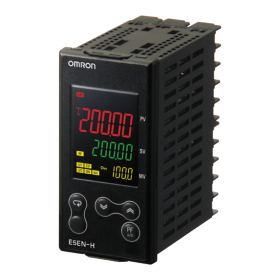
Names of parts on front panel
• Mode key
Press this key to change the
contents of the display.
Press this button for 1 s or
longer for reverse scroll.
• Level key
Use this key to change levels:
• Press the
key and the
M
key
together for at least 3 seconds to
switch to protect level.
• Function key/Auto/Manual key
Press this function key to operate
the function set with the PF Setting.
Operation menu
Input Type
Input type
Input
Setting
Input Setting range
0
-200.0 to 850.0(°C)
/ -300.0 to 1500.0 (°F)
Platinum
Pt100
1
-199.9 to 500.0(°C)
/ -199.9 to 900.0 (°F)
resistance
2
0.0 to 100.0(°C)
/
0.0 to 210.0 (°F)
thermometer
3
-199.9 to 500.0(°C)
/ -199.9 to 900.0 (°F)
JPt100
4
0.0 to 100.0(°C)
/
0.0 to 210.0 (°F)
-200.0 to 1300.0(°C)
K
5
/-300.0 to 2300.0 (°F)
6
-20.0 to 500.0(°C)
/
0.0 to 900.0 (°F)
Thermocouple
J
7
-100.0 to 850.0(°C)
/-100.0 to 1500.0 (°F)
8
-20.0 to 400.0(°C)
/
0.0 to 750.0 (°F)
9
-200.0 to 400.0(°C)
/-300.0 to 700.0 (°F)
T
-199.9 to 400.0(°C)
10
/-199.9 to 700.0 (°F)
11
E
-200.0 to 600.0(°C)
/-300.0 to 1100.0 (°F)
12
L
-100.0 to 850.0(°C)
/-100.0 to 1500.0 (°F)
U
13
-200.0 to 400.0(°C)
/-300.0 to 700.0 (°F)
14
-199.9 to 400.0(°C)
/-199.9 to 700.0 (°F)
15
-200.0 to 1300.0(°C)
N
/-300.0 to 2300.0 (°F)
16
R
0.0 to 1700.0(°C)
/
0.0 to 3000.0 (°F)
17
S
0.0 to 1700.0(°C)
/
0.0 to 3000.0 (°F)
B
18
100.0 to 1800.0(°C)
/ 300.0 to 3200.0 (°F)
19
0.0 to 2300.0(°C)
/
0.0 to 3200.0 (°F)
W
PL II
20
0.0 to 1300.0 (°C)
/
0.0 to 2300.0 (°F)
21
-50.00 to 200.00(°C)
/ -50.00 to 200.00(°F)
K
22
-50.00 to 200.00(°C)
/ -50.00 to 200.00(°F)
J
23
-50.00 to 200.00(°C)
/ -50.00 to 200.00(°F)
T
Platinum
24
Pt100
-50.00 to 200.00(°C)
/ -50.00 to 200.00(°F)
resistance
thermometer
25
4 to 20mA
One of the following ranges is used depending on scaling.
Current input
0 to 20mA
26
-19999 to 32400
1 to 5V
27
-1999.9 to 3240.0
Voltage input
28
0 to 5V
-199.99 to 324.00
-19.999 to 32.400
0 to 10V
29
*The default is"5".
*s.err will be displayed when a platinum resistance thermometer is mistakenly connected while
input type is not set for it. To clear the s.err display, correct the wiring and cycle the power supply.
Alarms
Alarm output function
Setting
Alarm type
Positive alarm value (X) Negative alarm value (X)
Output off
No alarm function
0
*1
1
Deviation upper/lower limit
X
2
ON
Deviation upper limit
OFF
SP
X
ON
3
Deviation lower limit
OFF
SP
L H
4
*1
ON
Deviation upper/lower range
OFF
SP
L H
Deviation upper/lower limit
ON
5
*1
standby sequence ON
OFF
SP
X
Deviation upper limit
ON
6
standby sequence ON
OFF
SP
X
Deviation lower limit
ON
7
standby sequence ON
OFF
SP
X
ON
8
Absolute value upper limit
OFF
0
X
ON
9
Absolute value lower limit
OFF
0
X
Absolute value upper limit
ON
10
standby sequence ON
OFF
0
X
Absolute value lower limit
ON
11
standby sequence ON
OFF
0
LBA (only for alarm 1)
12
13
PV change rate alarm
X
RSP absolute value upper limit
ON
14
OFF
0
X
ON
RSP absolute value lower limit
15
OFF
0
*1: Upper and lower limits can be set for parameters 1, 4 and 5 to provide for
different types of alarm. These are indicated by the letter "L" and "H".
• The default alarm type is "2"
Error display (troubleshooting)
When an error has occurred, the No.1 display shows the error code. Take
necessary measure according to the error code, referring the table below.
No.1 display
Meaning
Action
Check the setting of the Input Type parameter, check
Input error
the input wiring, and check for broken or shorts in the
s.err
(S. Err)
*2
temperature sensor.
After the correction of A/D converter error, turn the
power OFF then back ON again. If the display
remains the same, the controller must be repaired.
A/D converter error
e333
If the display is restored to normal, then a
(E333)
*2
probable cause can be external noise affecting the
control system. Check for external noise.
Turn the power OFF then back ON again. If the
display remains the same, the controller must be
repaired. If the display is restored to normal, then
e111
Memory error
(E111)
a probable cause can be external noise affecting
the control system. Check for external noise.
If the input value exceeds the display limit (
-
19999 to 32400), though it is within the control
range, [[[[ will be displayed under −19999 and ]]]] above 32400. Under these conditions,
control output and alarm output will operate normally.
Refer to E5CN-H/E5AN-H/E5EN-H User's Manual Advanced Type (Cat. No. H157) for details of control range.
*2: Error shown only for "Process value / Set point". Not shown for other status.
Warning Symbols
CAUTION
Do not touch the terminals while power is being supplied.
Doing so may occasionally result in minor injury due to electric shock.
Do not allow pieces of metal, wire clippings, or fine metallic shavings or filings from installation to
enter the product. Doing so may occasionally result in electric shock, fire, or malfunction.
Do not use the product where subject to flammable or explosive gas. Otherwise, minor injury from
explosion may occasionally occur.
Never disassemble, modify, or repair the product or touch any of the internal parts. Minor electric
shock, fire, or malfunction may occasionally occur.
CAUTION - Risk of Fire and Electric Shock
a) This product is UL listed as Open Type Process Control Equipment. It must be mounted in an enclosure that
does not allow fire to escape externally.
b) More than one disconnect switch may be required to de-energize the equipment before servicing.
c) Signal inputs are SELV, limited energy.
d) Caution: To reduce the risk of fire or electric shock, do not interconnect the outputs of different Class 2 circuits.
If the output relays are used past their life expectancy, contact fusing or burning may occasionally occur. Always
consider the application conditions and use the output relays within their rated load and electrical life expectancy.
The life expectancy of output relays varies considerably with the output load and switching conditions.
Tighten the terminal screws to between 0.74 and 0.90 N•m. Loose screws may occasionally result in fire.
Set the parameters of the product so that they are suitable for the system being controlled. If they are not suitable,
unexpected operation may occasionally result in property damage or accidents.
A malfunction in the Digital Controller may occasionally make control operations impossible or prevent
alarm outputs, resulting in property damage. To maintain safety in the event of malfunction of the Digital
Controller, take appropriate safety measures, such as installing a monitoring device on a separate line.
Suitability for Use
OMRON shall not be responsible for conformity with any standards, codes, or regulations that
apply to the combination of the products in the customer's application or use of the product.
Take all necessary steps to determine the suitability of the product for the systems, machines,
and equipment with which it will be used.
Know and observe all prohibitions of use applicable to this product.
NEVER USE THE PRODUCTS FOR AN APPLICATION INVOLVING SERIOUS RISK TO LIFE
OR PROPERTY WITHOUT ENSURING THAT THE SYSTEM AS A WHOLE HAS BEEN
DESIGNED TO ADDRESS THE RISKS, AND THAT THE OMRON PRODUCT IS PROPERLY
RATED AND INSTALLED FOR THE INTENDED USE WITHIN THE OVERALL EQUIPMENT
OR SYSTEM.
See also Product catalog for Warranty and Limitation of Liability.
Installation
Individual mounting (mm)
In the pack:
• Main unit
• Watertight packing
• Two mounting brackets
• Instruction manual
• Terminal cover
(Provided only for models
with "-500" suffix.)
Solderless terminal size: M3.5
Terminal cover:
(Model: E53-COV16)
USB-Serial Conversion Cable
(Sold Separately)(E58-CIFQ1)
+ 0.6
45
0
• No.1 display
Operation indicators
Process value or set data symbol
• No.2 display
• SUB1: Auxiliary output 1 indicator
Set point, set data read-out value or changed
input value
• No. 3 display
• SUB2: Auxiliary output 2 indicator
MV, Soak Time Remain, and Bank No. .
• Up and Down keys
Use the keys to change the values displayed on
the No.2 display.
• SUB3: Auxiliary output 3 indicator
Each press of
U
key increments or advances the
values displayed on the No.2 display.
Each press of
D
key decrements or returns the
• HA: Heater burnout alarm/Heater short
values displayed on the No.2 display.
Initial Setting Level
Operation stopped.
(Control/alarm are both stopped.)
in-t
Input Type
*3
5
in-h
Scaling Upper Limit
*6
(only when setting analog input)
100
in-l
Scaling Lower Limit
*6
(only when setting analog input)
0
dp
Decimal Point
*6
(only when setting analog input)
0
c
°C=
Temperature Unit
d-u
f
°F=
*6
c
(C stands for Celsius, F for Fahrenheit)
sl-h
SP Upper Limit
1300.0
sl-l
:
SP Lower Limit
-200.0
cntl
PID ON/OFF
onof
In ON/OFF control =
pid
pid
In 2-PID control =
Standard or Heating/Cooling
stnd
s-hc
Standard control =
h-c
Heating and cooling control =
stnd
(Select standard control or heating
and cooling control as required)
st
ST (Self-tuning)
*6
on
ST ON =
on
off
ST OFF =
ptrn
Program Pattern
off
Vary with "L", "H" values
cp
*6
Control Period (Heating)
X
20
ON
(Unit: Seconds)
OFF
SP
X
c-cp
ON
Control Period (Cooling)
*6
OFF
(Unit: Seconds)
20
SP
Vary with "L", "H" values
Direct/Reverse Operation
orev
or-r
=
In Reverse Operation (Heating)
or-r
or-d
In Direct Operation (Cooling)
=
Vary with "L", "H" values
alt1
X
ON
*3
*6
Alarm 1 Type: Specified models only
OFF
2
*4
SP
X
ON
OFF
alh1
SP
*6
Alarm 1 Hysteresis
X
0.2
ON
OFF
0
alt2
*3
X
*6
ON
Alarm 2 Type: Specified models only
*4
2
OFF
0
X
ON
alh2
OFF
*6
0
Alarm 2 Hysteresis
0.2
X
ON
OFF
0
tr-t
*6
Transfer Output Type
off
tr-h
*6
Transfer Output Upper Limit
100.0
X
ON
OFF
0
tr-l
*6
X
Transfer Output Lower Limit
ON
0.0
OFF
0
sqr
Extraction of Square Root Enable
*6
(Only when analog input is set)
off
amov
Move to Advanced
*6
Function Setting Level
0
Status at error
Control
Alarm
output
Operates
Initial setting level enables users to specify their
as above the
preferred operating conditions (input type, alarm type,
OFF
upper limit.
control method, etc.)
OFF
OFF
* 3: Refer to the adjoining tables for details of input types and alarm types.
* 4: Applicable only to models with alarm functions.
* 5: Operation is stopped when moved to the initial setting level.
(control/alarm are both stopped.)
OFF
OFF
* 6: The grayed-out setting items may not be displayed according to the models
and setting.
* 7: This function is supported only by models with heater burnout detection.
Precautions for Safe Use
Be sure to observe the following precautions to prevent operation failure, malfunction, or adverse affects on the performance
and functions of the product. Not doing so may occasionally result in unexpected events.
Use the product within specifications.
(1) The product is designed for indoor use only. Do not use the product outdoors. Do not use or store the product in any of
the following locations.
• Places directly subject to heat radiated from heating equipment.
• Places subject to splashing liquid or oil atmosphere.
• Places subject to direct sunlight.
• Places subject to dust or corrosive gas (in particular, sulfide gas and ammonia gas).
• Places subject to intense temperature change.
• Places subject to icing and condensation.
• Places subject to vibration and large shocks.
(2) Use/store within the rated temperature and humidity ranges.
Provide forced-cooling if required.
(3) To allow heat to escape, do not block the area around the product.
Do not block the ventilation holes on the product.
(4) Be sure to wire properly with correct polarity of terminals.
(5) Use specified size (M3.5, width 7.2 mm or less) crimped terminals for wiring. To connect bare wires to the terminal
block, use copper braided or solid wires with a gage of AWG24 to AWG14 (equal to a cross-sectional area of 0.205 to
2.081 mm
2
). (The stripping length is 5 to 6 mm.). Up to two wires of same size and type, or two crimped terminals can
be inserted into a single terminal.
(6) Do not wire the terminals which are not used.
(7) Allow as much space as possible between the controller and devices that generate a powerful high-frequency or
surge.Separate the high-voltage or large-current power lines from other lines, and avoid parallel or common wiring with
the power lines when you are wiring to the terminals.
(8) Use this product within the rated load and power supply.
(9) Make sure that the rated voltage is attained within two seconds of turning ON the power using a switch or relay contact.
If the voltage is applied gradually, the power may not be reset or output malfunctions may occur.
(10) Make sure that the Digital Controller has 30 minutes or more to warm up after turning ON the power before starting
actual control operations to ensure the correct temperature display.
(11) When executing self-tuning, turn the load and the unit ON simultaneously, or turn the load ON before you turn the
controller ON.
(12) A switch or circuit breaker should be provided close to this unit.The switch or circuit breaker should be within easy
reach of the operator, and must be marked as a disconnecting means for this unit.
(13) Always turn OFF the power supply before pulling out the interior of the product, and never touch nor apply shock to the
terminals or electronic components. When inserting the interior of the product, do not allow the electronic components
to touch the case.
(14) Do not use paint thinner or similar chemical to clean with. Use standard grade alcohol.
(15) Design system (control panel, etc) considering the 2 second of delay that the controller's output to be set after power
ON.
(16) The output may turn OFF when shifting to certain levels. Take this into consideration when performing control.
(17) The number of non-volatile memory write operations is limited. Therefore, use RAM write mode when frequently
overwriting data during communications or other operations.
(18) Refer to the instruction sheet for installing Option unit (E53-AKB/E53-EN01/E53-EN03).
(19) Read the information provided in the catalog and manual and be sure you understand it before attaching a Control Output
Unit.
(20) When disassembling the Temperature Controller for disposal, use suitable tools.
(21) Do not use the Temperature Controller if the front sheet is peeling or torn.
Mounting the output unit
{OUT}
E53-RN
When waterproofing is
OUT1
E53-QN
required, fit watertight
E53-Q3
packing on the backside of
E53-Q4
front panel.
E53-C3N
OUT2
E53-C3DN
E53-V34N
E53-V35N
Output placement is not required on the E5EN-HPRR@@
• Insert the main unit through the mounting hole in the panel (1-8 mm
thickness). Insert the mounting brackets (supplied) into the fixing
slots located on the top and bottom of the rear case.
• Alternately tighten the top and bottom screws on the mounting
fixtures applying equal pressure a little at a time until the rachet
rotates freely.
• When more than one machine is installed, make sure that the
ambient temperature does not exceed the specified limit.
• Do not use the clamps provided with the E53 for the E5EN-H.
• OUT1: Control output 1 indicator
Lit when control output 1 is ON and not
Lit when the function assigned to auxiliary
lit when it's OFF.
output 1 is ON.
For a current output, lit except for a 0% output.
• OUT2: Control output 2 indicator
Lit when control output 2 is ON and not
Lit when the function assigned to auxiliary
output 2 is ON.
lit when it's OFF.
For a current output, lit except for a 0% output.
• STOP: control stop indicator
Lit when the function assigned to auxiliary
Lit when event input or "Run/Stop" is
output 3 is ON.
stopped during operation.
During control stop, functions other than
control output are valid.
alarm/Heater overcurrent alarm indicator
• CMW: communications writing enable/
Lit when a heater burnout alarm,heater short
disable indicator
alarm, or heater overcurrent alarm has
Lit when communications writing is
occurred.
"enabled" and is out when it is "disabled".
• RSP:Lit when Remote SP Mode is set.
The setting data for the E5EN-HAA2HBF is shown here as an example.
Check the wiring before turning ON the power supply.
POWER ON
*5
Operation Level
25.0
PV/SP
s.err is displayed when
connected sensor is
0.0
25.0
different from input type.
0.0
bank
*6
Bank No.
0
Hold
down
rsp
*6
for at least
Remote SP Monitor
0.0
3 seconds
(No.1display flushes,
sp-m
Set Point During
then the control stops.)
*6
SP Ramp
0.0
Heater Current 1
ct1
Hold
down
*6
Value Monitor
for at least
0.0
(Unit: A)
1 second
Leakage Current 1
lcr1
*6
Value Monitor
0.0
(Unit: A)
prst
*6
Program Start
rset
sktr
*6
Soak Time Remain
0
RUN/STOP
r-s
*6
When control start
run
When control stop
al-1
*6
Alarm Value 1
0.0
al1h
*6
Alarm Value Upper Limit 1
0.0
al1l
*6
Alarm Value Lower Limit 1
0.0
al-2
*6
Alarm Value 2
0.0
al2h
*6
Alarm Value Upper Limit 2
Advanced Function
0.0
Setting Level
al2l
*6
Alarm Value Lower Limit 2
init
0.0
Hold
down
Parameter
off
for at least
Initialization
1 second
Operation level should normally
be used during operations.
Moving to the next level is
possible when the
and M keys down
Hold
password(-169) is input.
for at least 1 seconds
Protect Level
oapt
Operation / Adjustment
Protect
0
icpt
Initial Setting /
AT (auto-tuning)
Communication Protect
0
• AT in Adjustment level
Designate "at-2: 100% AT execute" or
wtpt
at-1: 40%
Setting Change Protect
AT execute" to execute AT and
"at-1 : 40%
off
"off : AT cancel"
to cancel AT.
"at" flashes
pfpt
"100%AT Execute"
PF Key Protect
off
at
at
U
prlp
off
at-2
D
Password to Move
"AT cancel"
0
to Protect Level
Also when AT execution ends, the
display automatically returns to "
off ".
Restricts which settings can be displayed
or changed, and restricts change by key
operation.
Other functions
For details about advanced function
setting level, bank setting level,pid
setting level,monitor/setting item
level, or manual control level, refer to
E5CN-H/E5AN-H/E5EN-H Digital Con-
trollers User's Manual Advanced Type
(Cat. No. H157).
For communications details, refer to
E5CN-H/E5AN-H/E5EN-H Digital
Controllers Communications Manual
Advanced Type (Cat. No. H159).
Power supply voltage
Operating voltage range
Power consumption
Indication accuracy
(Ambient temperature: 23°C) (±0.1 % of indication value or ±1°C,
Event input
Contact input
No-contact input
Control output 1,2
Control method
Auxiliary outputs
Ambient temperature
Ambient humidity
Storage temperature
Altitude
Recommended fuse
Weight
Degree of protection
Installation environment
Memory protection
Input
Transfer output
Connections
(The applicability of the electric terminals varies with the type of machine.)
• 100 to 240 VAC
Event Inputs
• 24 VAC/VDC (no polarity)
1
21
11
Control output 1, 2
Input power supply
Relay output
EV2
2
22
12
250 VAC, 5A
EV1
(resistive load)
+
3
23
13
SSR output
Control output 1
CT2
75-250 VAC, 1A
Potentiometer
(resistive load)
4
24
14
-
O
CT1
Control Output Unit
+
5
25
15
Control output 1, 2
W
Control output 2
CT2
6
26
16
-
C
+
DO NOT
DO NOT
7
27
17
USE
USE
Auxiliary output
Auxiliary output 2
A
DO NOT
DO NOT
1, 2, 3
8
28
18
USE
USE
V
Relay outputs
-
B
9
29
19
250 VAC, 3 A
-
(resistive load)
Auxiliary output 1
B
DO NOT
10
20
30
+
USE
The E5@N-H is set for a K thermocouple (input type of 5) by default. If a different sensor is
used, an input error (s.err) will occur. Check the setting of the Input Type parameter.
• The last character of the lot number "R" indicates that reinforced insulation is provided between input power supply, relay outputs, and between other
terminals.
• °C / °F : temperature unit
The temperature unit is displayed
when the displayed value is a
temperature.
When this parameter is set to "°C",
"C" is displayed, and when set to
"°F", "
" is displayed.
F
This flashes while ST (Self-Tuning) is
activated.
•
: Protection indicator
Lit when Setting Change Protect is
ON (disables the Up and Down Keys).
• MANU: Manual output indicator
Lit when the Auto/Manual Mode is set
to Manual Mode.
Adjustment Level
l.adj
*6
(The No. 3 display
has been omitted.)
spmd
*6
Press
ct1
*6
(less than
1 second)
hb1
*6
●
oc1
*6
Bank Setting Level
*7
lcr1
d.bnk
Display Bank
*6
*7
Selection
0
Press
(less than
hs1
*6
1 second)
Press
(less than
ins
*6
1 second)
●
PID Setting Level
insh
run
=
*6
stop
=
d.pid
Display PID
1
insl
Selection
*4
*6
Press
*6
(less than
*4
1 second)
*6
233.0
*4
*4
Protection function
Protection function, to prevent unwanted settings, restricts the setting items to be used
or designates if operation of the key is valid or invalid.
Operation / Adjustment protection
*4
The following table shows the relationship between settings and protect limits related to
Operation level and Adjustment level.
*4
Level
Process value
Operation level
PV/SP
Others
Adjustment level
and M keys down
Hold
for at least 3 seconds
Initial setting/Communications protection
This protect level restricts movement to the initial setting level,
communications setting level and advanced function setting level.
Initial setting
Communications
Set value
level
0
1
×
2
Setting change protection
Setting changes by key operation are restricted.
OFF "off": Setting can be changed by key operation
ON "on"
: Setting cannot be changed by key operation ("
(Protect level settings can all be changed.)
PF key protection
PF Key operation can be enabled or disabled.
OFF "off": PF Key enabled.
ON "on" : PF Key disabled.
OMRON EUROPE B.V.
Wegalaan 67-69, NL-2132 JD Hoofddorp The Netherlands
Phone 31-2356-81-300
FAX 31-2356-81-388
OMRON ELECTRONICS LLC
One Commerce Drive Schaumburg, IL 60173-5302 U.S.A
Phone 1-847-843-7900
FAX 1-847-843-7787
OMRON ASIA PACIFIC PTE. LTD.
No. 438A Alexandra Road # 05-05/08 (Lobby 2),
Alexandra Technopark, Singapore 119967
Phone 65-6835-3011
FAX 65-6835-2711
OMRON Corporation
Shiokoji Horikawa, Shimogyo-ku, Kyoto 600-8530 JAPAN
Specifications
100 to 240 VAC, 50/60 Hz or
24 VAC, 50/60 Hz /
24VDC
85 to 110% of the rated voltage
Approx. 12 VA (100 to 240 VAC)
Approx. 8.5 VA (24 VAC)/5.5 W (24 VDC)
Thermocouple:
whichever is greater) ±1 digit max.
Platinum resistance thermometer:
(±0.1 % of indication value or ±0.5°C,
whichever is greater) ±1 digit max.
Analog input: ±0.1 % FS ±1 digit max.
Output current: approx. 7 mA per contact.
ON:1 k Ω max., OFF: 100 kΩ min.
ON: residual voltage 1.5 V max.,
OFF: leakage current 0.1 mA max.
Relay output: SPST-NO,
250 VAC, 5 A (resistive load)
Electrical life of relay: 100,000 operations
SSR output 75-250 VAC, 1A (resistive load)
Control Output Unit
ON/OFF or 2-PID control
Relay outputs: SPST-NO,250 VAC, 3 A
(resistive load),
Electrical life of relay: 100,000 operations
–10 to 55°C
(Avoid freezing or condensation)
RH 25 to 85%
–25 to 65°C
(Avoid freezing or condensation)
Max. 2,000 m
T2A, 250 VAC, time-lag,
low-breaking capacity
Approx. 260 g (main unit only)
Front panel: IP66
Rear case: IP20, Terminal section: IP00
Installation category II, pollution
degree 2 (as per IEC61010-1)
Non-volatile memory
(Number of write operations: 1,000,000)
Position proportional potentiometer input,
Remote SP input
4 to 20 mA DC, Load: 600 Ω max.
Communications
RS-232C
RS-485
RS-422
SD
RDB
B(+)
11
11
11
RD
RDA
A(-)
12
12
12
SG
SG
13
13
13
DO NOT USE
21
DO NOT USE
SDB
B(+)
21
21
21
Auxiliary
22
DO NOT USE
SDA
A(-)
output 3
22
22
22
14
23
EV3
15
24
EV4
16
25
DO NOT
26
DO NOT
USE
A heater burnout alarm, Heater Short
USE
+
+
alarm, heater overcurrent alarm, or
27
Transfer output
4-20mA DC
input alarm is output to the output to
mA
(Load: 600 Ω
28
max.)
which the alarm 1 function is assigned.
-
-
+
29
DO NOT
4-20 mA DC
Remote SP input
USE
30
-
Conformance to EN/IEC Standards
This is a class A product.
In residential areas it may cause radio
interference, in which case the user may
be required to take adequate measures
to reduce interference.
Conformance to Safety Standards
Reinforced insulation is
provided between input power
supply, relay outputs, and
between other terminals.
Only the value set to the "ins: Temperature Input Shift" parameter is
applied to the entire temperature input range. When the process value is
200 °C, the process value is treated as 201.2 °C after input shift if the
input shift value is set to 1.2 °C.
The process value is treated as 198.8 °C after input shift if the input shift
value is set to –1.2 °C.
d
*6
Derivative Time
Adjustment Level
(Unit: secs)
40.0
AT Execute/Cancel
at
c-sc
Cooling Coefficient
at-2
*6
100%AT Execute
off
1.00
at-1
40%AT Execute
c-db
Dead Band
*6
SP Mode
0.0
lsp
Heater Current 1
of-r
Manual Reset Value
*6
Value Monitor
(Unit: %)
0.0
50.0
*7
(Unit: A)
Heater Burnout
hys
Hysteresis
*6
Detection 1
(Heating)
0.0
1.0
*7
(Unit: A)
Heater Overcurrent
chys
Hysteresis
Detection 1
*6
(Cooling)
50.0
1.0
*7
(Unit: A)
Leakage Current 1
soak
Value Monitor
*6
Soak Time
0.0
1
(Unit: A)
*7
wt-b
HS Alarm 1
*6
Wait Band
(Unit: A)
*7
50.0
off
sprt
Temperature Input Shift
*6
SP Ramp Set Value
(Unit:°C or°F)
0.00
off
Upper Limit Temperature
ol-h
Input Shift Value
MV Upper Limit
*6
when 2 point input shift
0.00
105.0
is selected
Lower Limit Temperature
ol-l
Input Shift Value
*6
MV Lower Limit
when 2 point input shift
0.00
-5.0
is selected
p
orl
*6
Proportional Band
MV Change Rate Limit
8.0
0.0
i
sqrp
Extraction of Square
Integral Time
*6
Root Low-cut Point
(Unit: secs)
0.0
Adjustment level is for entering set
values and shift values for control.
: Can be displayed and changed
Set value
: Can be displayed
0
1
2
3
× : Display or shifting to another
level is not possible.
×
×
×
×
×
Default setting : 0
: Change to
Advanced function
other levels
setting level
setting level
possible
× : Change to
other levels
×
not possible
×
×
0
Default setting :
" will light.)
Advertisement

Related Manuals for Omron E5EN-H


Summary of Contents for Omron E5EN-H
- Page 1 Controllers Communications Manual Phone 65-6835-3011 Refer to E5CN-H/E5AN-H/E5EN-H User's Manual Advanced Type (Cat. No. H157) for details of control range. Advanced Type (Cat. No. H159). FAX 65-6835-2711 *2: Error shown only for "Process value / Set point". Not shown for other status.
- Page 2 ●警告表示 ●仕様 安全上の要点 電源電圧 AC100-240V 50/60Hz 形 E5EN-H 注意 またはAC24V 50/60Hz/DC24V 許容電圧変動範囲 定格電圧の85~110% 製品の動作不良、誤動作または性能・機能への悪影響を防ぐため、以下のことを守ってください。不具合事象が稀 感電により軽度の傷害が稀に起こる恐れがあります。 デジタル調節計 消費電力 約12VA(AC100-240V) に起こることがあります。仕様外の取扱いはしないでください。 通電中は端子に触らないでください。 (1) 屋内専用機器のため屋内のみで使用してください。ただし、下記の環境では使用、または保管はしないでください。 約8.5VA(AC24V)/約 5.5W(DC24V) 軽度の感電、発火、機器の故障が稀に起こる恐れがあります。製品の中に金属、導線または、取り付け加工中の切粉 ・加熱機器から輻射熱を直接受けるところ ・水がかかるところ、被油のあるところ 指示精度 熱電対: (指示値の±0.1 % または±1℃ などが入らないようにしてください。 ・直射日光が当たるところ ・温度変化の激しいところ (周囲温度:23℃) の大きい方)± 1ディジット以下 取扱説明書 ・氷結、結露の恐れのあるところ...
Need help?
Do you have a question about the E5EN-H and is the answer not in the manual?
Questions and answers