Omron E5CN-HT User Manual
Digital controllers programmable type
Hide thumbs
Also See for E5CN-HT:
- Communications manual (128 pages) ,
- Instruction manual (2 pages) ,
- Instruction manual (2 pages)

Related Manuals for Omron E5CN-HT


Summary of Contents for Omron E5CN-HT
- Page 1 E5CN-HT E5CN-HT E5CN-HT E5AN-HT E5AN-HT E5AN-HT E5EN-HT E5EN-HT E5EN-HT Digital Controllers User's Manual Programmable Type Cat. No. H169-E1-01...
- Page 3 E5CN-HT E5AN-HT E5EN-HT Digital Controllers User’s Manual Programmable Type Produced December 2010...
- Page 5 • Up to 8 programs (patterns) can be created and each program can have up to 32 segments (steps). This manual describes the E5CN-HT, E5AN-HT, and E5EN-HT. Read this manual thoroughly and be sure you understand it before attempting to use the Digital Controller and use the Digital Controller cor- rectly according to the information provided.
- Page 6 OMRON. No patent liability is assumed with respect to the use of the information contained herein. Moreover, because OMRON is con- stantly striving to improve its high-quality products, the information contained in this manual is subject to change without notice.
- Page 7 WHETHER SUCH CLAIM IS BASED ON CONTRACT, WARRANTY, NEGLIGENCE, OR STRICT LIABILITY. In no event shall the responsibility of OMRON for any act exceed the individual price of the product on which liability is asserted. IN NO EVENT SHALL OMRON BE RESPONSIBLE FOR WARRANTY, REPAIR, OR OTHER CLAIMS...
- Page 8 Performance data given in this manual is provided as a guide for the user in determining suitability and does not constitute a warranty. It may represent the result of OMRON's test conditions, and the users must correlate it to actual application requirements. Actual performance is subject to the OMRON Warranty and Limitations of Liability.
-
Page 9: Safety Precautions
Safety Precautions ■ Definition of Precautionary Information The following notation is used in this manual to provide precautions required to ensure safe usage of the product. The safety precautions that are provided are extremely important to safety. Always read and heed the information provided in all safety precautions. The following notation is used. - Page 10 ■ Safety Precautions CAUTION Do not touch the terminals while power is being supplied. Doing so may occasionally result in minor injury due to electric shock. Do not allow pieces of metal, wire clippings, or fine metallic shav- ings or filings from installation to enter the product. Doing so may occasionally result in electric shock, fire, or malfunction.
- Page 11 CAUTION Tighten the terminal screws to between 0.74 and 0.90 N·m. Loose screws may occasionally result in fire. Set the parameters of the product so that they are suitable for the system being controlled. If they are not suitable, unexpected operation may occasionally result in property damage or accidents.
- Page 12 Precautions for Safe Use Be sure to observe the following precautions to prevent operation failure, malfunction, or adverse affects on the performance and functions of the product. Not doing so may occasionally result in unexpected events. Do not handle the Controller in ways that exceed product specifications. The product is designed for indoor use only.
- Page 13 16) The number of nonvolatile memory write operations is limited. Therefore, use RAM write mode when frequently overwriting data during communications or other operations. 17) Always touch a grounded piece of metal before touching the Digital Controller to discharge static electricity from your body.
- Page 14 If the measurement accuracy is low, check to see if input shift has been set correctly. ● Waterproofing The degree of protection is as shown below. Sections without any specification on their degree of pro- tection or those with IP@0 are not waterproof. Front panel: IP66 Rear case: IP20, Terminal section: IP00 To install the Controller so that it is waterproof, insert the Waterproof Packing.
-
Page 15: Precautions For Operation
Precautions for Operation It takes approximately two seconds for the outputs to turn ON from after the power supply is turned ON. Due consideration must be given to this time when incorporating Digital Controllers into a control panel or similar device. Make sure that the Digital Controller has 30 minutes or more to warm up after turning ON the power before starting actual control operations to ensure the correct temperature display. -
Page 16: Conventions Used In This Manual
Conventions Used in This Manual Meanings of Abbreviations The following abbreviations are used in parameter names, figures and in text explanations. These abbreviations mean the following: Symbol Term Process value Set point Set value Auto-tuning Heater burnout Heater short (See note 1.) Heater overcurrent Loop burnout alarm Engineering unit (See note 2.) - Page 17 How to Read Display Symbols The following tables show the correspondence between the symbols displayed on the displays and alphabet characters. The default is for 11-segment displays. a b c d e f g h i j k l m A B C D E F G H I J K L M n o p q r s t u v w x y z N O P Q R S T U V W X Y Z...
- Page 18 xviii...
-
Page 19: Table Of Contents
TABLE OF CONTENTS SECTION 1 Introduction........Names of Parts . - Page 20 TABLE OF CONTENTS 4-12 Performing Manual Control..........4-13 Using the Transfer Output .
-
Page 21: About This Manual
Section 5 describes the individual parameters used to set up, control, and monitor operation. • Operations for Applications Sections 4 and 5 describes the operating methods required to get the most out of the E5CN-HT, E5AN-HT, or E5EN-HT, such as functions related to program operation. - Page 22 xxii...
-
Page 23: Introduction
SECTION 1 Introduction This section introduces the features, components, and main specifications of the E5CN-H, E5AN-H, and E5EN-H Digital Controllers. Names of Parts ..........1-1-1 Front Panel . -
Page 24: Names Of Parts
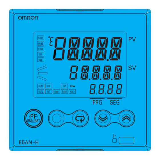
Names of Parts Section 1-1 Names of Parts 1-1-1 Front Panel E5CN-HT Temperature unit No. 1 display Operation indicators No. 2 display Level Key Down Key Mode Key Up Key E5AN-HT Temperature unit No. 1 display Operation indicators Program Status Indicators No. -
Page 25: Explanation Of Indicators
Section 1-1 Names of Parts E5EN-HT Operation indicators No. 1 display Temperature unit Program Status No. 2 display Indicators No. 3 display Operation indicators Up Key Mode Key PF Key Run/Reset Key Infrared Communications Light Receiver Down Key Level Key 1-1-2 Explanation of Indicators No. - Page 26 Names of Parts Section 1-1 3. OUT1 (Control Output 1) Lit while the control output function assigned to control output 1 is ON. For a linear output, however, OFF only for a 0% output. With position-proportional models, OUT1 is lit while the "open" output is OUT2 (Control Output 2) Lit while the control output function assigned to control output 2 is ON.
-
Page 27: Using The Keys
Mode Key and Up Key are pressed at the same time for at least one second. They perform the same function as the PF Key. If you are using the E5CN-HT, use the M+U Keys whenever the manual says to use the PF Key. -
Page 28: I/O Configuration And Main Functions
Section 1-2 I/O Configuration and Main Functions I/O Configuration and Main Functions 1-2-1 I/O Configuration E5CN-HT Control Control output Temperature input Control output 1 section (heating) or analog input Control output (cooling) Control output 2 Heating/cooling Alarm 3 CT1 input... - Page 29 E53-@@@@ 2 3 4 5 1 2 3 4 1. Type 1. Applicable Controller H: Advanced CN: E5CN-HT, E5CN-H or E5CN T: Programmable type 2. Function 1 2. Control Output 1 Blank: None R: Relay output Control output 2 (voltage output for...
- Page 30 Section 1-2 I/O Configuration and Main Functions E5AN/EN-HT Control output Control Control output 1 Temperature input section (heating) or analog input Control output Control output 2 (cooling) Heating/cooling RSP input error Alarm 3 Alarm 2 Auxiliary output 2 CT1 input Alarm 1 HB alarm CT2 input...
-
Page 31: Main Functions
Section 1-2 I/O Configuration and Main Functions Model Number Structure Model Number Legends Controllers Option Units E5AN/E5EN-@@@@@@@@M@-500 E53-@ 2 3 4 5 6 7 8 9 1. Type 1. Function H: Advanced EN01: RS-232C T: Programmable type communications EN02: RS-422 2. - Page 32 • A control output can be a relay output, voltage output (for driving SSR), linear voltage output, or current output, depending on the model. • With the E5CN-HT@2@@, auxiliary output 2 is used as control output (cooling) when heating/cooling control is selected. (It is also possible to allocate a different output.) Therefore, use auxiliary output 1 if an auxiliary...
- Page 33 I/O Configuration and Main Functions Section 1-2 Transfer Output A 4 to 20-mA transfer output can be used with the E53-CN@FN2 for the E5CN-H, or the E5AN/EN-HT@@F-500. Remote SP Inputs Remote SP inputs can be used with the E5AN-HT and E5EN-HT. Infrared Communications When Support Software, such as CX-Thermo version 4.30 or later (EST2-2C- MV4 or later), is used, the personal computer can be connected to the Digital...
-
Page 34: Setting Level Configuration And Key Operations
Setting Level Configuration and Key Operations Section 1-3 Setting Level Configuration and Key Operations Parameters are divided into groups, each called a level. Each of the set val- ues (setting items) in these levels is called a parameter. The parameters on the E5CN/AN/EN-HT are divided into the following 9 levels. - Page 35 (3) From the manual control level, key operations can be used to move to the operation level only. (4) When the PF Setting parameter is set to A-M. For the E5CN-HT, press the M+U Keys at the same time to implement the PF Key.
- Page 36 Setting Level Configuration and Key Operations Section 1-3 Monitor/Setting Item Level • To switch to the monitor/setting item level, press the PF Key from the operation level, program setting level, adjustment level, or PID setting level. The contents set for monitor/setting items 1 to 5 can be displayed. You can move from the monitor/setting item level to the operation level or initial setting level.
-
Page 37: Communications Function
U or D Keys. Communications Function The E5CN-HT, E5AN-HT, and E5EN-HT Digital Controllers are provided with communications to enable parameters to be checked and set from a host computer. If communications is required, use a model that supports communi- cations (E5@N-HT@@@03, E5@N-HT@@@01, or E5AN/EN-HT@@@02). - Page 38 Section 1-4 Communications Function 3. Select the parameters as shown below by pressing the M Key. 4. Press the U or D Key to change the parameter setting. Protocol Setting psel u-no Communications Unit No. Communications Baud Rate Communications Data Length (See note.) sbit Communications Stop Bits...
-
Page 39: Insulation Block Diagrams
Insulation Block Diagrams Section 1-5 Insulation Block Diagrams This section provides the insulation block diagrams for the E5CN-HT, E5AN- HT, and E5EN-HT. E5CN-HT Transfer output Temperature input, analog input, CT input, and voltage pulse output Communications and event inputs Power... - Page 40 Section 1-5 Insulation Block Diagrams...
-
Page 41: Preparations
SECTION 2 Preparations This section describes the work required to prepare the E5CN-HT, E5AN-HT, and E5EN-HT Digital Controllers for operation, including installation and wiring. Installation........... . -
Page 42: Installation
Section 2-1 Installation Installation 2-1-1 Dimensions Unit: mm E5CN-HT E5AN-HT 79.2 E5EN-HT 79.2... -
Page 43: Panel Cutout
Installation Section 2-1 2-1-2 Panel Cutout Unit: mm E5CN-HT Individual Mounting Group Mounting +1.0 number of Units 2.5) E5AN-HT Individual Mounting Group Mounting (See note.) +1.0 number of Units 3.5) Note Group mounting is not possible if an E53-C3N or E53-C3DN Out- put Unit is used for control output 1 or 2. - Page 44 60 min. • Waterproofing is not possible when group mounting several Controllers. • The recommended panel thickness is 1 to 5 mm for E5CN-HT, and 1 to 8 mm for E5AN/E5EN-HT. • Units must not be group mounted vertically. Also, group mounting is not possible if an E53-C3N or E53-C3DN Output Unit is used for control out- put 1 or 2.
-
Page 45: Mounting
Controllers. Waterproof packing is not necessary when there is no need for the waterproofing function. 2. Insert the E5CN-HT into the mounting hole in the panel. 3. Push the adapter from the terminals up to the panel, and temporarily fasten the E5CN-HT. - Page 46 Installation Section 2-1 Mounting the Terminal Cover Make sure that the "UP" mark is facing up, and then attach the E53-COV17 Terminal Cover to the holes on the top and bottom of the Digital Controller. E5AN/EN-HT Panel Mounting Bracket Terminal Cover (E53-COV16) Waterproof packing E5AN-HT...
- Page 47 Section 2-1 Installation Mounting to the Panel 1,2,3... 1. For waterproof mounting, waterproof packing must be installed on the Controller. Waterproofing is not possible when group mounting several Controllers. Waterproof packing is not necessary when there is no need for the waterproofing function.
-
Page 48: Removing The Digital Controller From The Case
PCBs are parallel to each other, make sure that the sealing rubber is in place, and press the E5CN-HT all the way to the rear case. While push- ing the E5CN-HT into place, push down on the hooks on the top and bot- tom surfaces of the rear case so that the hooks are securely locked in place. - Page 49 Installation Section 2-1 E5AN/EN-HT Tool insertion hole Tool insertion hole Flat-blade screwdriver (Unit: mm) 1,2,3... 1. Insert a flat-blade screwdriver into the two tool insertion holes (one on the top and one on the bottom) to release the hooks. 2. Insert a flat-blade screwdriver in the gap between the front panel and rear case (two on the top and two on the bottom), and use it to pry and pull out the front panel slightly.
- Page 50 Section 2-1 Installation Gap between the Front Panel and Rear Case Gap between the Front Panel and Rear Case Four gaps, two on the top and two on the bottom Four gaps, two on the top and two on the bottom Top View of E5EN-HT Top View of E5AN-HT 3.
- Page 51 Section 2-1 Installation 1,2,3... 1. While lifting the hooks securing the PCB on the front panel, remove the PCB to which the sockets are attached. Hooks securing PCB Hooks securing PCB E5AN-HT E5EN-HT 2. Set the Output Unit for control output 1 in the OUT1 socket. Set the Output Unit for control output 2 in the OUT2 socket.
-
Page 52: Wiring Terminals
Section 2-2 Wiring Terminals Wiring Terminals Check the terminal arrangements for E5CN-HT terminals 1 to 15 and E5AN/ EN-HT terminals 1 to 30 as marked on the product label and on the side of the case. 2-2-1 Terminal Arrangement E5CN-HT The default is for a K-type thermocouple (input type = 5). - Page 53 Section 2-2 Wiring Terminals Note Wire all voltage input terminals correctly. The Digital Controller may fail if the voltage input terminals are wired incorrectly. Control outputs that are voltage outputs are not isolated from the internal circuits. When using a grounded thermocouple, do not connect any of the control output ter- minals to ground.
- Page 54 Section 2-2 Wiring Terminals E5AN/EN-HT The default setting is for a K-type thermocouple Communications (input type = 5). If a different sensor is used, an E53-EN01 E53-EN03 E53-EN02 input error (s.err) will occur. Check the setting of RS-232C RS-485 RS-422 the Input Type parameter.
-
Page 55: Precautions When Wiring
Controller and the right side represents the outside. Power supply • With the E5CN-HT, connect to terminals 9 and 10; with the E5AN-HT and E5EN-HT, connect pins 1 and 2. The following table shows the specifica- tions. - Page 56 Section 2-2 Wiring Terminals Control Output 1 • Outputs are sent from terminals 1 and 2 with the E5CN-HT and from pins 3 and 4 with the E5AN/EN-HT. The following diagrams show the available outputs and their internal equalizing circuits.
- Page 57 (for driving SSR), however, are functionally isolated from the internal cir- cuits. Control Output 2 • Outputs are sent from terminals 11, 12, 14, and 15 with the E5CN-HT, and from pins 5 and 6 with the E5AN/EN-HT. The following diagrams show the available outputs and their internal equalizing circuits.
- Page 58 (for driving SSR), however, are functionally isolated from the internal cir- cuits. • Control output 2 of the E5CN-HT is a voltage output (for driving SSR) only, and outputs across terminals 11(+) and 12(-), or 14(+) and 15(-). • Control output 1 (voltage output for driving SSR) and control output 2 (voltage output for driving SSR) are not isolated.
- Page 59 • When the HB alarm, HS alarm, or heater overcurrent alarm is used with the E5AN-HT/EN-HT, alarms are output across terminals 9 and 10. • On the E5CN-HT, when heating/cooling control is used, auxiliary output 2 becomes control output (cooling).
- Page 60 E53-CN@H@N2 E53-CN@HH@N2 E5AN/EN-HT@@H@-500 E5AN/EN-HT@@HH@-500 (for E5CN-HT) Transfer Output • On the E5CN-HT@M@-500 with an E53-CN@FN2, the transfer output is output across terminals 14 and 15. • On the E5AN/EN-HT@@F-500, transfer output is output across terminals 27 and 28. Current Current...
- Page 61 Communications RS-485 • When communications are to be used with the E53-CN@03N2 for the E5CN-HT, or E53-EN03 for the E5AN/EN-HT, connect communications cable across terminals 11 and 12 or 21 and 22. B(+) A( ) Do not use.
- Page 62 AWG24: 0.205 mm AWG14: 2.081 mm RS-232C • When communications are to be used with the E53-CN@01N2 for the E5CN-HT, or the E53-EN01 for the E5AN/EN-HT, connect communica- tions cable across terminals 11 to 13. RS-232C E53-CN@01N2 (for E5CN-HT) E53-EN01 (for E5AN/EN-HT)
- Page 63 Wiring Terminals Section 2-2 • A 1:1 connection is used. The maximum cable length is 15 m. • Use AWG24 (cross-sectional area: 0.205 mm ) to AWG14 (cross-sec- tional area: 2.081 mm ) shielded twisted-pair cable. Cross-sectional area of conductor AWG24: 0.205 mm AWG14: 2.081 mm RS-422 (E5AN/EN-HT Only)
-
Page 64: Using The Support Software Port
CX-Thermo higher than 4.30, or other Support Software. The E58- CIFQ1 USB-Serial Conversion Cable is required to make the connection. For information concerning the models that can be used with CX-Thermo, contact your OMRON sales representative. Procedure Use the following procedure to connect the Digital Controller to the personal computer using the USB-Serial Conversion Cable. -
Page 65: Using Infrared Communications
E5EN-HT. The infrared communications port and the Setup Tool port cannot be used at the same time. For information concerning the models that can be used with the CX-Thermo, contact your OMRON sales representatives. Procedure Use the following procedure to connect the Digital Controller to the personal computer using the USB-Infrared Conversion Cable. - Page 66 Using Infrared Communications Section 2-4 3. Enabling Digital Controller Infrared Communications Mount the Digital Controller to the panel and wire it. Turn ON the power supply for the Digital Controller, go to the adjustment level, and set the In- frared Communications Use parameter to ON. When this parameter is set to ON, the Ir indicator on the front panel of the Digital Controller will light.
- Page 67 Section 2-4 Using Infrared Communications and Setup Manual for details on checking the COM port assigned to the USB-Infrared Conversion Cable. The communications conditions for infra- red COM ports are fixed as shown in the table below. Set the communica- tions conditions for the CX-Thermo Setup Tool according to the following table.
- Page 68 Section 2-4 Using Infrared Communications...
-
Page 69: Basic Operation
SECTION 3 Basic Operation This section describes the basic operation of the E5CN-H, E5AN-H, and E5EN-H Digital Controllers, including key operations to set parameters and descriptions of display elements based on specific control examples. Initial Setting Examples ......... Setting the Input Type . -
Page 70: Initial Setting Examples
Section 3-1 Initial Setting Examples Initial Setting Examples Initial hardware setup, including the sensor input type, alarm types, control periods, and other settings is done using parameter displays. The O and M Keys are used to switch between parameters, and the amount of time that you press the keys determines which parameter you move to. - Page 71 Section 3-1 Initial Setting Examples Example 1 (Models with Standard or Heating/Cooling Control) Setup Procedure Input type: 5 (K thermocouple, 200.0 C to 1,300.0 C) Power ON Power ON Control method: ON/OFF control If the power supply is Alarm type: 2 (upper limit) turned ON before the sensor is wired,...
- Page 72 Section 3-1 Initial Setting Examples Example 2 (Models with Standard or Heating/Cooling Control) Setup Procedure Input type: 9 (T thermocouple, 200.0 C to 400.0 C) Power ON Power ON Control method: PID control PID constants found using auto-tuning (AT). If the power supply Alarm type: 2 upper limit is turned ON before...
- Page 73 Section 3-1 Initial Setting Examples Example 3 (Models with Position-proportional Control) Input type: 5 (K thermocouple, 200.0 C to 1,300.0 C) Control method: Floating control (default) Setup Procedure Travel time: 45 s Power ON Power ON Set point Segment 3 Segment 1 Segment 2 Operation Level...
-
Page 74: Setting The Input Type
Section 3-2 Setting the Input Type Setting the Input Type The Controller supports 3 input types: platinum resistance thermometer, ther- mocouple, and analog inputs. Set the input type that matches the sensor that is used. 3-2-1 Input Type The following example shows how to set a K thermocouple for 20.0 to 500.0 C. - Page 75 Section 3-2 Setting the Input Type Input type Specifications Set value Input temperature setting range Platinum resistance Pt100 50.0 to 200.0 ( C)/ 50.0 to 200.0 ( F) thermometer Current input 4 to 20 mA Either of the following ranges, by scaling: 19999 to 32400 0 to 20 mA 1999.9 to 3240.0...
-
Page 76: Selecting The Temperature Unit
Section 3-3 Selecting the Temperature Unit Selecting the Temperature Unit 3-3-1 Temperature Unit • Either C or F can be selected as the temperature unit. • Set the temperature unit in the Temperature Unit parameter of the initial setting level. The default is c ( C). Operating Procedure The following example shows how to select C as the temperature unit. -
Page 77: Setting Output Specifications
Section 3-5 Setting Output Specifications Setting Output Specifications The following table shows the parameters related to outputs. Each of the parameters is described in detail following the table. Parameter Standard Position- models proportional models ● Control Period (Heating) ● c-cp Control Period (Cooling) ●... -
Page 78: Assigned Output Functions
Section 3-5 Setting Output Specifications For example, when the process value (PV) is lower than the set point (SP) in a heating control system, the manipulated variable increases according to the difference between the PV and SP. Accordingly, reverse operation is used in a heating control system. - Page 79 Alarm 2 sub3 Auxiliary Output 3 Assignment Alarm 3 (E5AN/EN-H only) • Each output is automatically initialized as shown below by changing the control mode. Example: E5CN-HT Parameter name Symbol Without control output 2 With control output 2 Standard Heating/cooling...
- Page 80 Section 3-5 Setting Output Specifications 3. Press the U Key to set the parameter to h-c. Initial Setting Level Note The following output assignments do not need to be set because they 5-hc are set automatically by changing the control mode, but they are shown here as a reference for checking the assignments for each out- put.
- Page 81 Section 3-5 Setting Output Specifications 14. Press the O Key for at least one second to move from the advanced Initial Setting Level function setting level to the initial setting level. Input Type in-t 15. Press the O Key for at least one second to move from the initial setting Operation Level level to the operation level.
-
Page 82: Setting Programs
Section 3-6 Setting Programs Setting Programs 3-6-1 Outline of Program Functions • Up to 8 programs (patterns) can be created and each program can have up to 32 segments (steps). Program 7 (highest program number) Program 1 Program 0 point Segment 31 (highest segment Segment 1... -
Page 83: Program Setting Example
Section 3-6 Setting Programs • The setting range is END or 0 to No. of Segments Used 1. The default is END (segment setting completed). Setting the Segment Set • For step time programming, each segment has a Segment Set Point Points and Segment parameter and a Segment Time parameter. - Page 84 Section 3-6 Setting Programs 4. Press the M Key to select the Number of Segments Used parameter. s-no 5. Press the UD Keys to change the setting to 4. 6. Press the M Key to select the Display Segment Selection parameter. d.seg 7.
-
Page 85: Using On/Off Control
Section 3-7 Using ON/OFF Control 27. Press the O Key three times to move from the program setting level to Operation Level the operation level. 30.0 50.0 Using ON/OFF Control In ON/OFF control, the control output turns OFF when the temperature being controlled reaches the preset set point. -
Page 86: Settings
Section 3-7 Using ON/OFF Control Reverse operation Dead band Hysteresis (heating) Hysteresis (cooling) Heating Cooling side side Set point Parameters Symbol Parameter: level Application s-hc Standard or Heating/Cooling: Initial setting level Specifying control method cntl PID ON/OFF: Initial setting level Specifying control method orev Direct/Reverse Operation: Initial setting level... -
Page 87: Determining The Pid Constants (At Or Manual Settings)
Section 3-8 Determining the PID Constants (AT or Manual Settings) Setting the Hysteresis Operating Procedure Set the hysteresis to 2.0 C. 1. Press the O Key twice to move from the operation level to the adjustment Operation Level level. PV/SP 25.0 100.0 Adjustment Level... - Page 88 Section 3-8 Determining the PID Constants (AT or Manual Settings) • Auto-tuning will stop if the Run/Reset parameter is set to Reset and the Reset Operation parameter is set to stop control, or if you switch to man- ual operation. •...
- Page 89 Section 3-8 Determining the PID Constants (AT or Manual Settings) AT Hysteresis The AT Hysteresis parameter sets the hysteresis when switching ON and OFF for the limit cycle operation during auto-tuning. Limit Cycle MV Amplitude The Limit Cycle MV Amplitude parameter sets the MV amplitude for limit cycle operation during auto-tuning.
-
Page 90: Rt (Robust Tuning)
Section 3-8 Determining the PID Constants (AT or Manual Settings) 4. To return to the operation level, press the O Key. Operation Level 25.0 Note PID Constants When control characteristics are already known, PID constants can be set directly to adjust control. PID constants are set in the Proportional Band (P), Integral Time (I), and Derivative Time (D) parameters, according to the Dis- play PID Selection parameter setting in the PID setting level. - Page 91 Section 3-8 Determining the PID Constants (AT or Manual Settings) Temperature Temperature Much hunting occurs. Hunting is reduced. Set value Set value Time Time Start of control Start of control • When the temperature (PV) falls short of the set point for the PID con- stants when using auto-tuning in normal mode, executing auto-tuning in RT Mode tends to improve performance.
-
Page 92: Manual Setup
Section 3-8 Determining the PID Constants (AT or Manual Settings) 5. Press the U Key to select on. off is the default. 6. To return to the initial setting level, press the O Key for at least one sec- Initial Setting Level ond. -
Page 93: Alarm Outputs
SP. Alarm Outputs • Alarms can be used with the E5CN-HT@2@@@ (two auxiliary outputs) or E5AN/EN-HT@2@@@ (two auxiliary outputs). Also, alarms 1 to 3 can be assigned to outputs using the Control Output 1/2 Assignment parameters to use alarms with models that have the following type of control outputs: relay outputs, voltage outputs (for driving SSR). -
Page 94: Alarm Types
Alarm Outputs Section 3-9 • This section describes the Alarm Type, Alarm Value, Upper-limit Alarm and Lower-limit Alarm parameters. 3-9-1 Alarm Types Set value Alarm type Alarm output operation Function When alarm value X When alarm value X is positive is negative Alarm function OFF Output OFF... - Page 95 Section 3-9 Alarm Outputs Set value Alarm type Alarm output operation Function When alarm value X When alarm value X is positive is negative Remote SP absolute This alarm type turns ON the value upper limit (See alarm when the remote SP (RSP) note 6.) is higher than the alarm value (X).
-
Page 96: Alarm Values
Alarm Outputs Section 3-9 3-9-2 Alarm Values • Alarm values are indicated by “X” in the table on the previous page. When the upper and lower limits are set independently, “H” is displayed for Alarm Lower Limit al1l upper limit values, and “L” is displayed for lower limit values. •... - Page 97 Section 3-9 Alarm Outputs 6. Press the M Key to select the Alarm Value 1 parameter. Alarm Value 1 al-1 7. Use the U Key to set 10.0. al-1 10.0 PV Change Rate Alarm The change width can be found for PV input values in any set period. Differ- ences with previous values in each set period are calculated, and an alarm is output if the result exceeds the alarm value.
-
Page 98: Using Heater Burnout, Heater Short, And Heater Overcurrent Alarms
Section 3-10 Using Heater Burnout, Heater Short, and Heater Overcurrent Alarms 3-10 Using Heater Burnout, Heater Short, and Heater Overcurrent Alarms 3-10-1 Heater Burnout, Heater Short, and Heater Overcurrent Alarm Operations • Heater burnout detection and heater overcurrent detection are executed by measuring heater current while the control output (heating) is ON, and heater short detection is executed by measuring heater current while it is OFF. -
Page 99: Installing Current Transformers (Ct)
• This function can be used with E5@N-HT models that have the HB alarm, HS alarm, and OC alarm. For the E5CN-HT, connect the CT in advance to terminals 14 and 15 (CT1), or 13 and 15 (CT2). For the E5AN-HT/EN-HT, connect the CT in advance to terminals 14 and 15 (CT1) or 15 and 16 (CT2). -
Page 100: Calculating Detection Current Values
Section 3-10 Using Heater Burnout, Heater Short, and Heater Overcurrent Alarms Load (such as a heater) AC line Load Product To CT input AC line Product To CT input ■ Star connecting lines: Refer to the following diagram for CT installation positions. -
Page 101: Application Examples
Section 3-10 Using Heater Burnout, Heater Short, and Heater Overcurrent Alarms • Make sure that the following conditions are satisfied: Heater with a current of less than 10.0 A: (Current value at normal operation) (Current value at heater burnout) When the difference is less than 1 A, detection is unstable. Heater with a current of 10.0 A or more: (Current value at normal operation) (Current value at heater burnout) - Page 102 Section 3-10 Using Heater Burnout, Heater Short, and Heater Overcurrent Alarms (Normal current) + (Heater burnout current) Heater burnout detection current = 15 + 10 = 12.5 [A] Three-phase Heaters Delta Connecting Lines Example: Using Three 200-VAC, 2-kW Heaters Normal 17.3 A 200 V 17.3 A...
- Page 103 Section 3-10 Using Heater Burnout, Heater Short, and Heater Overcurrent Alarms Star Connecting Lines Example: Using Three 200-VAC, 2-kW Heaters Normal 5.8 A 200 V Load (such as a heater) 200 V 5.8 A 200 V Product To CT input 5.8 A Product To CT input...
- Page 104 Section 3-10 Using Heater Burnout, Heater Short, and Heater Overcurrent Alarms V Connecting Lines Example: Using Two 200-VAC, 2-kW Heaters Normal 10 A Product 200 V To CT input 17.3 A 200 V 200 V 10 A Product To CT input Burnout 10 A 200 V...
-
Page 105: Settings: Hb Alarm
Section 3-10 Using Heater Burnout, Heater Short, and Heater Overcurrent Alarms 3-10-5 Settings: HB Alarm To activate the heater burnout alarm, set the HB ON/OFF parameter to ON in the advanced function setting level and set the Heater Burnout Detection 1 and Heater Burnout Detection 2 parameters in the adjustment level. -
Page 106: Settings: Heater Short Alarm
Section 3-10 Using Heater Burnout, Heater Short, and Heater Overcurrent Alarms 9. For this example, set 2.5. To return to the operation level, press the O Key twice. 3-10-6 Settings: Heater Short Alarm To activate the HS alarm, set the HS Alarm Use parameter to ON in the advanced function setting level and set the HS Alarm 1 and HS Alarm 2 parameters in the adjustment level. -
Page 107: Settings: Heater Overcurrent Alarm
Section 3-10 Using Heater Burnout, Heater Short, and Heater Overcurrent Alarms ■ HS Alarm Settings 5. Press the O Key for at least one second to move from the advanced Operation Level function setting level to the initial setting level. Press the O key again for PV/SP 25.0 at least one second to move to the operation level. - Page 108 Section 3-10 Using Heater Burnout, Heater Short, and Heater Overcurrent Alarms Advanced Function Setting Level The top parameter in the advanced function setting level is displayed. Move to the init Advanced Function Setting Level 4. Press the M Key to select the Heater Overcurrent Use parameter. Heater Check that this parameter is set to ON (the default), and then set the Overcurrent...
-
Page 109: Setting The No. 3 Display
Section 3-11 Setting the No. 3 Display 3-11 Setting the No. 3 Display This section describes how to set the No. 3 Display (E5AN-HT/E5EN-HT only) when the PV and SP are displayed. The program number and segment num- ber, or the MV can be displayed on the No. 3 display. 3-11-1 PV/SP Display Selection (spdp) The following table shows the set values and display contents for the PV/SP Display selection. - Page 110 Section 3-11 Setting the No. 3 Display Operating Procedure This procedure displays the PV, SP, and MV and the PV, SP, program number, and segment number when the PV and SP are displayed. The PV/SP Display Screen Selection parameter is set to 2. 1.
-
Page 111: Starting And Stopping Operation (Rtsm)
Section 3-12 Starting and Stopping Operation (rtsm) 3-12 Starting and Stopping Operation (rtsm) To start program operation, set the Run/Reset parameter to Run. To stop pro- gram operation, set the Run/Reset parameter to Reset. Program execution will stop while the Hold parameter is set to ON. The program number can be changed only in reset status. - Page 112 Section 3-12 Starting and Stopping Operation (rtsm) Set point Segment 1 Segment 0 Segment 2 100.0 50.0 Fixed SP 0.40 0.20 0.20 Time (h.min) Startup Operation • This parameter determines the operating status when the power is turned (p-on) ON. You can select any of the following four settings. The specified star- tup operation is also used for software resets and when moving from ini- tial setting level to operation level.
-
Page 113: Adjusting Programs
Section 3-13 Adjusting Programs 3-13 Adjusting Programs The temperature vector will change if the program is changed during opera- tion when the Step Time/Rate of Rise Programming parameter is set to Step Time. The following sections show how the temperature vector will changed. 3-13-1 Changing the SP If the SP is changed during a segment, the present SP will move in a straight line with the changed SP as the target point. - Page 114 Section 3-13 Adjusting Programs...
-
Page 115: Applications Operations
SECTION 4 Applications Operations This section describes scaling, program-related functions, and other special functions that can be used to make the most of the functionality of the E5CN-H, E5AN-H, and E5EN-H Digital Controllers. Shifting Input Values..........4-1-1 Shifting Inputs . - Page 116 4-15-3 SP Mode (spmd) ........4-15-4 Wait (wt-b) .
-
Page 117: Shifting Input Values
Section 4-1 Shifting Input Values Shifting Input Values 4-1-1 Shifting Inputs Either a 1-point shift or a 2-point shift can be used to shift the input. The default setting is for a 1-point shift. To execute a 2-point shift, change the Input Shift Type parameter (istp) setting (advanced function setting level) to ins2. -
Page 118: How To Calculate Input Shift Values For A 2-Point Shift
Section 4-1 Shifting Input Values Two-point shift • Separate shift values can be set for the upper limit and lower limit of the Upper-limit insh sensor input range for an infrared sensor as well as for a thermocouple or Temperature platinum resistance thermometer with the Input Shift Type parameter Input Shift Value (istp) set to ins2. - Page 119 Section 4-1 Shifting Input Values 3. After setting the input shift values, check the Controller readout (A) and the control target temperature (B). If they are approximately the same, this completes setting the input shift. Figure 1 Controller readout (A) (C) Control target After shifting Controller readout after...
-
Page 120: Adjusting Alarms
Section 4-2 Adjusting Alarms a. Lower-limit temperature input shift value insl = {(X2 Y1)} + (X1 b. Upper-limit temperature input shift value insh = {(X2 Y1)} + (X1 3. After setting the calculated values to insl and insh, check the Digital Controller readout (A) and thermometer temperature (B). -
Page 121: Standby Sequence
Section 4-2 Adjusting Alarms 4-2-2 Standby Sequence • The standby sequence can be used so that an alarm will not be output until the process value leaves the alarm range once and then enters it again. • For example, with a lower limit alarm, the process value will normally be below the set point, i.e., within the alarm range, when the power supply is turned ON, causing an alarm to be output. -
Page 122: Setting Scaling Upper And Lower Limits For Analog Inputs
Section 4-3 Setting Scaling Upper and Lower Limits for Analog Inputs Summary of Alarm The following figure summarizes the operation of alarms when the Alarm Type Operation parameter is set to “lower-limit alarm with standby sequence” and “close in alarm” is set. Alarm type: Lower-limit alarm with standby sequence Alarm value Alarm hysteresis... -
Page 123: Executing Heating/Cooling Control
Section 4-4 Executing Heating/Cooling Control Operating Procedure In this example scaling is set to display 4 to 20 mA as 10.0% to 95.0%. 1. Press the O Key for three seconds to move from the operation level to Initial Setting Level the initial setting level. - Page 124 Section 4-4 Executing Heating/Cooling Control Example: E5CN-H Parameter name Symbol Without control output 2 With control output 2 Standard Heating/cooling Standard Heating/cooling out1 Control Output 1 Control output Control output Control output Control output Assignment (heating) (heating) (heating) (heating) out2 Control Output 2 Not assigned.
-
Page 125: Settings
Section 4-4 Executing Heating/Cooling Control The cooling coefficient is multiplied by the P for the control output assigned to the heating side to obtain control with characteristics that differ from those of the control output assigned to the heating side. A cooling coefficient can be set for each PID set. - Page 126 Section 4-4 Executing Heating/Cooling Control 2. Select the PID1 Cooling Coefficient parameter by pressing the M Key. PID1 Cooling 1.csc Coefficient 1.00 3. Press the U and D Keys to set 10.00. 1.csc 10.00 Setting the Dead Band Operating Procedure Dead Band = 5 1.
-
Page 127: Using Event Inputs
• Event inputs can be used on the following models: Two Event Inputs; E5CN-HT@M@-500 with the E53-CN@B@N2 for the E5CN-HT E5AN/EN-HT@B@M@-500 for the E5AN/EN-HT Four Event Inputs; E5AN/EN-HT@B@M@-500 with the E53-AKB for the E5AN/EN-HT... - Page 128 Section 4-5 Using Event Inputs Setting Function at-2 100% AT Execute/Cancel at-1 40% AT Execute/Cancel (See note 4.) wtpt Setting Change Enable/Disable cmwt Communications Write Enable/Disable (See note 5.) Alarm Latch Cancel wait Wait Enable/Disable Note (1) The event input must be turned OFF first before this function can be ac- tivated again.
- Page 129 Section 4-5 Using Event Inputs Resetting a Program When the Event Input Assignment 1 or Event Input Assignment 2 parameter is set to RST (reset), control will stop when event input 1 or 2 turns ON. Alarm outputs, however, will be according to the PV. The RST (reset) indicator will light while control is stopped.
- Page 130 Section 4-5 Using Event Inputs Control by Inverting When DRS (Invert Direct/Reverse Operation) is set for the Event Input Direct/Reverse Assignment 1 or Event Input Assignment 2 parameter and the Direct/Reverse Operation parameter is set for reverse operation, control starts with direct Operation operation (cooling control) when event input 1 or 2 turns ON and control starts with reverse operation (heating control) when the event input turns OFF.
- Page 131 Section 4-5 Using Event Inputs Switching 100% AT When AT-2 (100% AT Execute/Cancel) is set for either the Event Input Assign- Execute/Cancel ment 1 or Event Input Assignment 2 parameter, 100% AT will be executed when event input 1 or 2 turns ON and will be cancelled when the input turns OFF.
-
Page 132: Setting The Sp Upper And Lower Limit Values
Section 4-6 Setting the SP Upper and Lower Limit Values Enabling and When the Event Input Assignment 1 or Event Input Assignment 2 parameter Disabling Wait is set to WAIT (wait enable/disable), wait operation will be enabled when event input 1 or 2 turns ON. When the input turns OFF, wait operation will be dis- Operation abled. -
Page 133: Moving To The Advanced Function Setting Level
Moving to the Advanced Function Setting Level Section 4-7 4-6-2 Setting Set the set point upper and lower limits in the Set Point Upper Limit and Set Point Lower Limit parameters in the initial setting level. In this example, it is assumed that the input type is set to a K thermocouple with a temperature range of 200.0 to 1300.0 C. - Page 134 Moving to the Advanced Function Setting Level Section 4-7 Protect Level 2. The Controller moves to the protect level, and the Operation/Adjustment Protect parameter is displayed. Operation/Adjust- oapt ment Protect 3. Press the M Key once to move to the Initial Setting/Communications Pro- Initial Setting/ icpt tect parameter.
-
Page 135: Using The Key Protect Level
Section 4-8 Using the Key Protect Level Using the Key Protect Level 4-8-1 Protection • To move to the protect level, press the O and M Keys at the same time for at least three seconds in the operation level, adjustment level, program setting level, or PID setting level. -
Page 136: Entering The Password To Move To The Protect Level
Using the Key Protect Level Section 4-8 Initial Setting/ This protect level restricts movement to the initial setting level, communica- Communications tions setting level, and advanced function setting level. Protect Initial setting level Communications Advanced function value setting level setting level icpt Possible to reach Possible to reach... - Page 137 Note Protection cannot be cleared or changed without the password. Be careful not to forget it. If you forget the password, contact your OMRON sales representative. Communications • The Write Variable operation command can be used via communications Operation Command to write the password to the Move to Protect Level parameter.
- Page 138 Section 4-8 Using the Key Protect Level and any Write Variable operation commands to write parameters in the protect level will result in operation errors. (2) If a password is not set or if it is set to 0, the display will change to the Operation/Adjustment Protect parameter and writing the parameters in the protect level will be enabled immediately.
-
Page 139: Pv Change Color
PV Change Color Section 4-9 PV Change Color 4-9-1 PV Color Change Function Use the PV color change function to change the color of the PV display (No. 1 display). There are three display colors, orange, red, and green, and you can select from the following four modes and nine functions. -
Page 140: Setting
Section 4-9 PV Change Color Mode Setting Function PV change color Application example Linked to PV stable stable stable band band band Within High Within PV stable High Application example band r-g.r Red to Green to Green To display stable status g-o.r Green to Green... - Page 141 Section 4-9 PV Change Color 1. Press the O Key for at least three seconds to move from the operation Initial Setting Level level to the initial setting level. Input Type in-t Initial Setting Level 2. Select the Move to Advanced Function Setting Level parameter by press- ing the M Key.
-
Page 142: Alarm Delays
Section 4-10 Alarm Delays 4-10 Alarm Delays 4-10-1 Alarm Delays • Delays can be set for the alarm outputs. ON and OFF delays can be set separately for alarms 1, 2, and 3. The ON and OFF delays for alarm 1 function only for the alarm function. - Page 143 Alarm Delays Section 4-10 Note (1) The defaults are 0, i.e., the ON and OFF delays are disabled. (2) The parameters are displayed when alarm functions are assigned and when the alarm type is set to any type but 0 (none), 12: LBA, or 13: PV change rate alarm.
-
Page 144: Loop Burnout Alarm
Loop Burnout Alarm Section 4-11 9. Press the O Key for at least one second to move from the initial setting Operation Level level to the operation level. PV/SP 25.0 100.0 4-11 Loop Burnout Alarm 4-11-1 Loop Burnout Alarm (LBA) •... - Page 145 Section 4-11 Loop Burnout Alarm • If a loop burnout occurs when the set point is near the ambient tempera- ture, the temperature deviation in a steady state may be less than the LBA level, preventing detection of the loop burnout. •...
- Page 146 Loop Burnout Alarm Section 4-11 Determining the LBA • To manually set the LBA detection time, set the LBA Detection Time Detection Time parameter to twice the LBA reference time given below. 1,2,3... 1. Set the output to the maximum value. 2.
- Page 147 Section 4-11 Loop Burnout Alarm 3. Press the U Key to set the parameter to 12. Initial Setting Level To return to the operation level, press the O Key for at least one second. alt1 4. Press the O Key to move from the operation level to the PID setting level. Operation Level PV/SP 25.0...
-
Page 148: Performing Manual Control
Section 4-12 Performing Manual Control 15. Press the O Key for at least one second to move from the advanced Initial Setting Level function setting level to the initial setting level. Input Type in-t 16. Press the O Key for at least one second to move from the initial setting Operation Level level to the operation level. - Page 149 Performing Manual Control Section 4-12 • The automatic display return function will not operate in manual mode. • Balanceless-bumpless operation will be performed for the MV when switching between manual and automatic operation. (See note.) • Switching between manual and automatic operation is possible for a maximum of one million times.
- Page 150 Section 4-12 Performing Manual Control (2) For Manual MV Limit Enable, this value will be between the MV lower limit and the MV upper limit. (3) This setting is enabled only when the Direct Setting of Position Propor- tional MV parameter is set to ON. Manual MV Limit When the Manual MV Limit Enable parameter is set to ON (enabled), the MV Enable (manl)
- Page 151 Section 4-12 Performing Manual Control Using the PF Key to • If the PF Setting parameter is set to A-M (auto/manual), you can change Move to the Manual to manual operation (manual control level) by pressing the PF Key for at least one second from the adjustment level, operation level, program set- Control Level ting level, or PID setting level.
- Page 152 Section 4-12 Performing Manual Control 6. Use the U Key to set the parameter to ON. (The default is ON.) amad 7. Press the O Key for at least one second to move from the advanced Initial Setting Level function setting level to the initial setting level. Input Type in-t 8.
-
Page 153: Using The Transfer Output
Section 4-13 Using the Transfer Output 4. Press the D Key to enter the password ( 169), and move from the initial Advanced Function Setting Level setting level to the advanced function setting level. Parameter init Initialization 5. Select the Auto/Manual Select Addition parameter by pressing the M Advanced Function Setting Level Key. - Page 154 Simple transfer out- 0.3% FS (See note 2.) Not supported. Note (1) For details on the calibration method, refer to SECTION 6 CALIBRATION. (2) E5CN-HT only. Transfer Output Type (tr-t) Transfer output type Symbol Setting range OFF (See note 1.)
- Page 155 Section 4-13 Using the Transfer Output When used as a control output, 3.7 mA will be output for 0% and 20.3 mA will be output for 100% so that the actuator is controlled at 0% or 100%. Output current (mA) 20.3 Transfer output value Control output...
- Page 156 Section 4-13 Using the Transfer Output Output current (mA) MV (%) Transfer output Transfer output lower limit upper limit (The above graph is for when the linear current output is set to 4 to 20 mA.) Operating Procedure The following procedure sets the transfer output for a present SP range of 50 to 200.
- Page 157 Section 4-13 Using the Transfer Output 7. Use the U Key to set the parameter to 50.0. The default is 200.0. tr-l -50.0 8. To return to the operation level, press the O Key for at least one second. Operation Level PV/SP 25.0 100.0...
-
Page 158: Using Pid Sets
Section 4-14 Using PID Sets 4-14 Using PID Sets PID Sets • The PID set to be executed is selected by using the PID Set No. parame- ter in the program setting level. If 0 (Automatic selection) is set, then the PID set will be selected automatically according to preset conditions. - Page 159 Section 4-14 Using PID Sets Automatic PID Set Selection • If the PID Set No. parameter for a program is set to 0, the PID set will be selected automatically according to preset conditions. In the setting example on the left (with the PID Set Automatic Selection Data parame- Automatic selection PID set range...
-
Page 160: Program-Related Functions
Section 4-15 Program-related Functions 4-15 Program-related Functions 4-15-1 Ramp Rate Programming • The following program parameters must be set if the Step Time/Ramp Rate Programming parameter is set to Ramp Rate Programming: Seg- ment Type, Segment Set Point, Segment Ramp Rate, and Segment Time. To use Ramp Rate programming, set the Step Time/Ramp Rate Program- ming parameter to Ramp Rate Programming. - Page 161 Section 4-15 Program-related Functions Set point Segment 2 Segment 0 Segment 1 100.0 50.0 PV at startup 0.40 0.20 0.20 = 20.0 Time (h.min) • If there is an input error when operation starts and the segment type of segment 0 is set to ramp or step, the program will start from the SP of segment 0.
-
Page 162: Controlling The Program
Section 4-15 Program-related Functions Changing Parameters • If the rate of rise is changed during a segment, both the slope of the present SP and the segment time for the ramp period will change. Set point After change Point of change Before change Time... -
Page 163: Sp Mode (Spmd)
Program-related Functions Section 4-15 Hold Status Displays Normal Displays 25.0 25.0 Alternate on the display. Example: PV/SP 100.0 hold 100.0 Note Priority of Flashing and Alternating Displays on No. 2 Display The priority for flashing and alternating displays is as follows: 1. -
Page 164: Wait (Wt-B)
Program-related Functions Section 4-15 Changing the SP • The following figure shows an example of changing between Program SP Mode Mode and Fixed SP Mode during program operation. Set point FSP changed to PSP. PSP changed to FSP. FSP changed. Time Segment N Segment N+1... -
Page 165: Time Signals
Section 4-15 Program-related Functions Set point Segment completed. Wait band Wait band Current segment Next segment Time Timer stopped. Timer started. • As soon as the deviation enters the wait band, the program moves to the next segment. • The wait operation is not performed if it is disabled by an event input. •... -
Page 166: Program Status Output
Program-related Functions Section 4-15 • If the OFF time is shorter than the ON time, the output remains ON from when the ON time has elapsed until the next OFF condition. • If an advance operation is executed, a time equivalent to the set pro- gram time will be considered to have elapsed. -
Page 167: Program Startup Operation
Section 4-15 Program-related Functions • The program end output is turned OFF if the Run/Reset parameter is changed to Run. If the Operation End Operation parameter is set to Fixed SP Control and the SP Mode is changed to Program SP Mode after the end of program operation, the program end output will turn OFF. - Page 168 Section 4-15 Program-related Functions ■ SP Start Operation starts as programmed from the SP of segment 0. However, if the Reset Operation parameter is set to fixed SP operation, program operation will start with the fixed SP or remote SP. ■...
-
Page 169: Operation End Operation (Eset)
Program-related Functions Section 4-15 4-15-8 Operation End Operation (eset) • The Operation End Operation parameter is used to select the operation after a program has been completed. The options are Reset, Continue, or Fixed SP Mode. Setting of Description Operation End Operation Reset (rst) Ends operation. -
Page 170: Output Adjustment Functions
Section 4-16 Output Adjustment Functions • Potentiometer Input Errors Timing will continue if a potentiometer input error occurs during program operation. • Setting Area 1 If you move to setting area 1, program operation will stop, the control out- puts will turn OFF, and the following outputs will turns OFF: time signal outputs, program end output, run output, and stage output. -
Page 171: Mv At Pv Error
Section 4-16 Output Adjustment Functions ■ Position-proportional Models Open, close, or hold status can be selected for floating control or when the Direct Setting of Position Proportional MV parameter is set to OFF. With open status, only the open output will turn ON. With close status, only the close out- put will turn ON. - Page 172 Section 4-16 Output Adjustment Functions ■ Position-proportional Models Open, close, or hold status can be selected for floating control or when the Direct Setting of Position Proportional MV parameter is set to OFF. With open status, only the open output will turn ON. With close status, only the close out- put will turn ON.
-
Page 173: Using The Extraction Of Square Root Parameter
Section 4-17 Using the Extraction of Square Root Parameter 4-17 Using the Extraction of Square Root Parameter Extraction of Square Roots Extraction of Square Root Enable • For analog inputs, the Extraction of Square Root parameter is provided for inputs so that differential pressure-type flow meter signals can be directly input. -
Page 174: Setting The Width Of Mv Variation
Section 4-18 Setting the Width of MV Variation 2. Use the U and D Keys to set the parameter to 25 (4 to 20 mA). in-t 3. Press the M Key to select the Extraction of Square Root Enable param- Extraction eter. - Page 175 Section 4-18 Setting the Width of MV Variation Parameter name Setting rage Unit Default MV Change Rate 0.0 to 100.0 Limit Operating Procedure This procedure sets the MV change rate limit to 5.0%/s. The related parame- ters are as follows: PID·ON/OFF = PID Operation Level PV/SP...
-
Page 176: Setting The Pf Key
4-19-1 PF Setting (Function Key) PF Setting • Pressing the PF Key for at least one second executes the operation set in the PF Setting parameter. (For the E5CN-HT, use the M+U Keys to implement the PF Key function.) Set value... - Page 177 Section 4-19 Setting the PF Key Monitor/Setting Item Monitor/Setting Item 1 Setting the PF Setting parameter to the Monitor/Setting Item makes it possi- ble to display monitor/setting items using the PF key. The following table pfd1 Item 5 shows the details of the settings. For setting (monitor) ranges, refer to the pfd5 applicable parameter.
- Page 178 Section 4-19 Setting the PF Key Operating Procedure This procedure sets the PF Setting parameter to PFDP, and the Monitor/Set- ting Item 1 parameter to 7 (Alarm Value 1). Operation Level PV/SP 25.0 100.0 1. Press the O Key for at least three seconds to move from the operation Initial Setting Level level to the initial setting level.
-
Page 179: Counting Control Output On/Off Operations
Section 4-20 Counting Control Output ON/OFF Operations 4-20 Counting Control Output ON/OFF Operations 4-20-1 Control Output ON/OFF Count Function If Control Output 1 and 2 are ON/OFF outputs (relay outputs, voltage outputs for driving SSR), the number of times that a control output turns ON and OFF can be counted. - Page 180 Section 4-20 Counting Control Output ON/OFF Operations ON/OFF Counter Reset Function The ON/OFF counter can be reset for a specific control output. Parameter name Setting range Unit Default ON/OFF Counter Reset 0: Disable the counter reset (rac) function. 1: Reset the control output 1 ON/OFF counter.
-
Page 181: Displaying Pv/Sv Status
Section 4-21 Displaying PV/SV Status 4-21 Displaying PV/SV Status 4-21-1 PV and SV Status Display Functions PV Status Display The PV function in the PV/SP, PV, or PV/Manual MV (Valve Opening) Display Function (pvst) and the control and alarm status specified for the PV and PV status display are alternately displayed in 0.5-s Set value Symbol... - Page 182 Section 4-21 Displaying PV/SV Status Set value Symbol Function Alarm 1 to 3 OR status ALM is alternately displayed when Alarm 1, 2, or 3 is set to ON. Heater Alarm (See note.) HA is alternately displayed when a heater burnout alarm, HS alarm, or heater over- current alarm is ON.
- Page 183 Section 4-21 Displaying PV/SV Status 6. Press the O Key for at least one second to move to the initial setting lev- Initial Setting Level Input Type in-t 7. Press the O Key for at least one second to move to the operation level. Operation Level If the Alarm 1 status is ON, PV and ALM1 will be alternately displayed.
-
Page 184: Using A Remote Sp
Section 4-22 Using a Remote SP 4-22 Using a Remote SP The remote SP function scales a remote SP input (4 to 20 mA) to the remote SP upper and lower limits, and takes it as the set point. (This function is sup- ported by the E5AN-HT and E5EN-HT only.) Set the Remote SP Enable parameter (advanced function setting level) to ON, and use an event input or an operation command to select the remote SP. - Page 185 Section 4-22 Using a Remote SP • An alarm can be output if an RSP input error occurs by setting the Remote SP Input Error Output parameter to ON. RSP (%) Remote SP upper limit +10% Remote SP upper limit Remote SP lower limit Remote SP lower limit 10% Input (mA)
- Page 186 Section 4-22 Using a Remote SP • The following figure shows SP tracking when the mode is changed from Program SP Mode to Fixed SP Mode. Set point Set point Time Time PSP changed to FSP. PSP changed to FSP. Without SP Tracking With SP Tracking Remote SP Broken-line...
-
Page 187: Position-Proportional Control
Section 4-23 Position-proportional Control 4-23 Position-proportional Control The control method used to adjust the opening and closing of a valve with a control motor is called "position-proportional control" or "ON/OFF servo con- trol." Either closed control or floating control can be selected for position-pro- portional control. - Page 188 Section 4-23 Position-proportional Control Position-proportional Dead Band and Open/Close Hysteresis The interval during which the valve output is held (for the ON and OFF switch- ing points for the open output and closed output) is set in the Position Propor- tional Dead Band parameter, and the hysteresis is set in the Open/Close Hysteresis parameter.
-
Page 189: Logic Operations
Section 4-24 Logic Operations Manual Operation With models that support position-proportional control, manual operation is possible by moving to the manual control level and pressing the Up and Down Keys. The output on the open side is ON while the Up Key is pressed, and the output on the closed side is ON while the Down Key is pressed. - Page 190 Section 4-24 Logic Operations • Select Logic Operation Editor from the CX-Thermo Options Menu. Making the Settings The following display will appear on the Logic Operation Editor Setting Win- dow. Set each of the parameters. 1,2,3... 1. Displaying the Library Import Dialog Box Logic operation samples for specific cases are set in the library in advance.
- Page 191 Section 4-24 Logic Operations Example: Selecting Library 1 2. Switching Work Bit Operations Select the work bit logic operations from the Operation of Work Bit 1 to Op- eration of Work Bit 8 Tab Pages. 3. Selecting the Operation Type From one to four operations are supported.
- Page 192 Section 4-24 Logic Operations • Operation 3 A or B or C or D When condition A, B, C or D is satisfied • Operation 4 A and B and C and D When conditions A, B, C and D are all satisfied...
- Page 193 Logic Operations Section 4-24 4. Selecting Input Assignments Select the input assignment for the work bit logic operation from the follow- ing settings. Parameter name Setting range Work Bit 1 Input Assignment A 0: Always OFF 1: Always ON 2: ON for one cycle when power is turned ON 3: Event Input 1 (external input) (See note 1.) 4: Event Input 2 (external input) (See note 1.) 5: Event Input 3 (external input) (See note 1.)
- Page 194 Logic Operations Section 4-24 Click the condition to switch between normally open and normally closed inputs A to D. Normally open Normally closed 6. Switching between Normally Open and Normally Closed for Work Bits Click the condition to switch between normally open and normally closed work bits.
- Page 195 Section 4-24 Logic Operations Select the setting for the event input assignment. When a work bit is selected as event input data, Communications Write Enable/Disable cannot be assigned to an event input. 12. Changing Control Output and Auxiliary Output Settings Control output and auxiliary output assignments can be changed.
- Page 196 Logic Operations Section 4-24 3. Set the operation by selecting one of the following: Work bit 1 input assignment A = 4: Event input 2 (ex- ternal input) Work bit 1 input assignment B = 0: Always OFF Work bit 1 input assignment C = 0: Always OFF Work bit 1 input assignment D = 0: Always OFF 4.
- Page 197 Section 4-24 Logic Operations 3. Select Library 1 from the library list, and then click the OK Button. Confirm the following settings, and then click the OK Button. Work bit 1 operation type: Operation 1 Work bit 1 input assignment A = 7: Alarm 1 Work bit 1 input assignment B = 19: Invert for Run (OFF)/Reset (ON) Work bit 1 input assignment C = 0: Always OFF...
- Page 198 Section 4-24 Logic Operations...
-
Page 199: Parameters
SECTION 5 Parameters This section describes the individual parameters used to setup, control, and monitor operation. Conventions Used in this Section ........5-1-1 Meanings of Icons Used in this Section . -
Page 200: Conventions Used In This Section
Section 5-1 Conventions Used in this Section Conventions Used in this Section 5-1-1 Meanings of Icons Used in this Section Describes the functions of the parameter. Function Describes the setting range and default of the parameter. Setting Used to indicate parameters used only for monitoring. Monitor Describes the parameter settings, such as those for Operation Commands, and procedures. -
Page 201: Protect Level
Section 5-2 Protect Level Protect Level Four levels of protection are provided: Operation/Adjustment Protect, Initial Setting/Communications Protect, Setting Change Protect, and PF Key Pro- tect. Each level is used to protect the corresponding settings and prevent acci- dental changes to the settings. Power ON Program Setting Operation Level... - Page 202 Section 5-2 Protect Level The Password to Move to Protect pmov Move to Protect Level Level password must not be set to 0. The password to move to the protect level is entered for this parameter. • The password to move to the protect level (i.e., the password set for the Password to Move to Protect Level parameter) is entered for this parame- ter.
- Page 203 • The all protect indication ( ) will light when setting is ON. pfpt PF Key Protect ■ PF Key Protect This parameter enables and disables PF Key operation. (For the E5CN-HT, press the M+U Keys simultaneously to implement the PF Key.) Function...
- Page 204 • Set this parameter to 0 when no password is to be set. ■ Related Parameters Move to protect level (protect level): Page 180 Note Protection cannot be cleared or changed without the password. Be careful not to forget it. If you forget the password, contact your OMRON sales representa- tive.
-
Page 205: Operation Level
Section 5-3 Operation Level Operation Level Display this level to perform operation. This level is used to run or reset a pro- gram and also to monitor the PV, SP or other values. In the advanced function setting level, you can set a parameter to hide or show the set points. - Page 206 Section 5-3 Operation Level Operation Level Page Page Process Value 25 .0 ct 2 Heater Current 2 Value Added when Additional Monitor PV display is ON. 25 .0 Process Value/ Leakage Current 1 lcr1 Set Point (See note.) Monitor Auto/Manual Switch a- m lcr2 Leakage Current 2...
- Page 207 Section 5-3 Operation Level The Additional PV Display parameter Process Value must be set to ON. The process value is displayed on the No. 1 display, and nothing is displayed on the No. 2 and No. 3 (E5AN/EN-HT only) displays. Function Monitor range Unit...
- Page 208 Section 5-3 Operation Level No. 3 Display (E5AN/EN-HT) The following table shows the contents of the No. 3 display, according to the setting of the PV/SP Display Screen Selection parameter. Set value Display contents Only the PV and SP are displayed. (The No. 3 display is not shown.) The PV, SP, Program No., and Segment No., and the PV, SP, and MV are displayed in order.
- Page 209 Section 5-3 Operation Level ■ Related Parameters PID ON/OFF (initial setting level): Page 238 Auto/manual select addition (advanced function setting level): Page 269 Program No. • This parameter specifies the program number to use for operation. • This parameter can be used only when resetting and only when the Event Input Assignment 1 to 4 parameters are not set to switch the program Function number.
- Page 210 Section 5-3 Operation Level The Event Input Assignment 1 to 4 parameters must not be set to Hold or Hold Clear, the Run/Reset param- hold Hold eter must be set to Run, operation must not be on standby, and opera- tion must be completed (Fixed SP Mode).
- Page 211 Section 5-3 Operation Level stbm Remaining Standby Time Monitor Operation must be on standby. • This parameter monitors the remaining standby time. Function Monitor range Unit Standby time in hours and min- Hours and minutes, or days utes: 0.00 to 99.59 and hours (See note.) Standby time in days and hours: Monitor...
- Page 212 Section 5-3 Operation Level The Run/Reset parameter must be rptm Program Execution Repetitions Monitor set to Run. • This parameter monitors the number of times the program has been repeated. Function Monitor range Unit 0 to 9,999 Repetitions Monitor ■ Related Information 4-15 Program-related Functions: Page 138 ■...
- Page 213 Section 5-3 Operation Level Heater burnout, HS alarm, and heater overcurrent detection must be supported. Heater Current 1 Value Monitor Alarm 1 must be assigned. The Heater Burnout Detection or Heater Overcurrent Use parameter must be set to ON. This parameter measures the heater current from the CT input used for detecting heater burnout.
- Page 214 Section 5-3 Operation Level Heater burnout, HS alarm, and heater overcurrent detection must be supported (two CTs). Heater Current 2 Value Monitor Alarm 1 must be assigned. The Heater Burnout Detection or Heater Overcurrent Use parameter must be set to ON. This parameter measures the heater current from the CT input used for detecting heater burnout.
- Page 215 Section 5-3 Operation Level Heater burnout, HS alarms, and heater overcurrent detection must be lcr1 Leakage Current 1 Monitor supported. The HS Alarm Use parameter must be set to ON. This parameter measures the heater current from the CT input used for detecting SSR short-circuits.
- Page 216 Section 5-3 Operation Level Run/Reset This parameter is used to start and stop operation. Operation will start when run (run) is selected and it will stop when rst (reset) is selected. The RST indicator will light while operation is stopped. Operation The default is rst.
- Page 217 Section 5-3 Operation Level ■ Related Parameters Standard or heating/cooling (initial setting level): Page 239 MV display (advanced function setting level): Page 262 Position-proportional control must be supported. The No. 3 display must be supported. Valve Opening Monitor The PV/SP Display Screen Selection parameter must be set to 1, 2, 4, or This parameter monitors the valve opening during operation.
-
Page 218: Program Setting Level
Section 5-4 Program Setting Level Program Setting Level The Program Setting Level is used to set the set points, times, rates of rise, and other parameters for each program. The program to which to move is selected in the first parameter in the Program Setting Level (Display Program Selection). - Page 219 Section 5-4 Program Setting Level Display Program Selection d.prg d.prg d.prg d.prg s-no Number of Segments Used, 1 to 32 Display Segment Selection, END or 0 to Number of Segments Used 1 d.seg d.seg d.seg d.seg Page Page p i d PID Set No.
- Page 220 Section 5-4 Program Setting Level d.prg Display Program Selection • This parameter specifies the number of the program to be set. Function Setting range Unit Default 0 to 7 See note. Setting Note Number of program currently used for control. ■...
- Page 221 Section 5-4 Program Setting Level ■ Related Information 3-6 Setting Programs: Page 60 The Display Segment Selection parameter must not be set to END. styp Segment n Type (n = 0 to 7) The Step Time/Rate of Rise Pro- gramming parameter must be set to Rate of Rise.
- Page 222 Section 5-4 Program Setting Level ■ Related Information 3-6 Setting Programs: Page 60 ■ Related Parameters Step time/rate of rise programming (initial setting level): Page 252 The Displayed Segment Selection parameter must not be set to END. The Step Time/Rate of Rise Pro- Segment n Ramp Rate (n = 0 to 7) gramming parameter must be set to Rate of Rise.
- Page 223 Section 5-4 Program Setting Level Setting range Unit Default 0.00 to 99.59 Hours and minutes, or minutes and seconds 0.00 Setting Note The unit is set in the Program Time Unit parameter. (The default is H-M (hours and minutes).) ■ Related Information 4-15 Program-related Functions: Page 138 ■...
- Page 224 Section 5-4 Program Setting Level Setting range Unit Default 19,999 to 32,400 Setting ■ Related Parameters Input type (initial setting level): Page 232 Scaling upper limit, Scaling lower limit, Decimal point (initial setting level): Page 237 Alarm 1 type (initial setting level): Page 240 Alarm 2 type (initial setting level): Page 244 Alarm 3 type (initial setting level): Page 245 Standby sequence reset (advanced function setting level): Page 258...
- Page 225 Section 5-4 Program Setting Level Scaling upper limit, Scaling lower limit, Decimal point (initial setting level): Page 237 Alarm 1 to 3 type (initial setting level): Page 240 Alarm 1 hysteresis (initial setting level): Page 244 Alarm 2 hysteresis (initial setting level): Page 244 Alarm 3 hysteresis (initial setting level): Page 244 Standby sequence reset (advanced function setting level): Page 258 Auxiliary output 1 open in alarm (advanced function setting level): Page 259...
- Page 226 Section 5-4 Program Setting Level ts1s Time Signal 1 Set Segment Outputs must be assigned to time signals 1 and 2. ts2s Time Signal 2 Set Segment • These parameters set the segment numbers that will use time signals. • Up to two outputs can be set for each program. There is one timing setting for each output.
- Page 227 Section 5-4 Program Setting Level Time Signal 1 OFF Time Outputs must be assigned to time signals 1 and 2. Time Signal 2 OFF Time • These parameters set the OFF times for the time signals. Function Setting range Unit Default 0.00 to 99.59 Hours and minutes, or...
-
Page 228: Adjustment Level
Section 5-5 Adjustment Level Adjustment Level This level is for executing AT (auto-tuning) and other operations, and for set- ting control parameters. This includes the basic Controller parameters for PID control (proportional band, integral time, derivative time) and heating/cooling control. Power ON Program Setting Operation Level... - Page 229 Section 5-5 Adjustment Level Adjustment Level Page Adjustment Level Display Page Page Page l. a dj Displayed only once when entering Heater Overcurrent Position c-sc adjustment level. Cooling Coefficient Detection 2 Proportional 1.00 50.0 Dead Band Leakage Current 1 Open/Close lcr1 c-db oc-h...
- Page 230 Section 5-5 Adjustment Level l.adj Adjustment Level Display This parameter is displayed after moving to the adjustment level. When a logic operation is set, a period "." will be displayed on the No. 2. dis- play. • This parameter indicates that the adjustment level has been entered. (The Adjustment Level parameter will not be displayed again even if the M Key is pressed in the adjustment level to scroll through the parame- Function...
- Page 231 Section 5-5 Adjustment Level ■ Related Parameters PID * proportional band, PID * Integral time, PID * Derivative time (PID setting level): Page 227 PID ON/OFF (initial setting level): Page 238 Communications must be supported. The Event Input Assignments 1 to 4 cmwt Communications Writing parameters must not be set to...
- Page 232 Section 5-5 Adjustment Level • In Remote SP Mode, the remove SP specified with an external signal (e.g., 4 to 20 mA) is used as the SP. Also, the RSP indicator will light. Setting range Default psp: Program SP Mode Setting fsp: Fixed SP Mode rsp: Remote SP Mode...
- Page 233 Adjustment Level Section 5-5 ■ Related Parameters Heater burnout detection 1, Heater burnout detection 2 (adjustment level): Page 211, 212 HB ON/OFF (advanced function setting level): Page 259 Heater overcurrent detection 1, Heater overcurrent detection 2 (adjustment level): Page 211, 213 Heater overcurrent use (advanced function setting level): Page 283 Error displays ct1: Page 320 Heater burnout, HS alarms, and...
- Page 234 Adjustment Level Section 5-5 ■ Related Parameters Heater current 1 value monitor (adjustment level): Page 191 Heater overcurrent use, Heater overcurrent latch, Heater overcurrent hystere- sis (advanced function setting level): Page 283, 284 Heater burnout, HS alarms, and heater overcurrent detection must be supported (two CTs).
- Page 235 Section 5-5 Adjustment Level • When the set value is 0.0, the heater burnout alarm output is turned OFF. When the set value is 50.0, the heater burnout alarm output is turned ON. Setting range Unit Default 0.0 to 50.0 Setting ■...
- Page 236 Adjustment Level Section 5-5 • HS alarms are not detected if the control output (heating) OFF time is 100 ms or less. Monitor range Unit 0.0 to 55.0 Monitor • ffff is displayed when 55.0 A is exceeded. • If an HS alarm 1 alarm is output, the HA indicator will light and the No. 1 display for the leakage current 1 monitor will flash.
- Page 237 Section 5-5 Adjustment Level • HS alarms are not detected if the control output (heating) OFF time is 100 ms or less. Monitor range Unit 0.0 to 55.0 Monitor • ffff is displayed when 55.0 A is exceeded. • If an HS alarm 2 alarm is output, the HA indicator will light and the No. 1 display for the leakage current 2 monitor will flash.
- Page 238 Section 5-5 Adjustment Level Setting range Unit Default 199.99 to 324.00 C or F 0.00 Setting ■ Related Parameters Input type (initial setting level): Page 236 Input shift type (advanced function setting level): Page 268 insh Upper-limit Temperature Input Shift Value The Input Type parameter must be set for a thermocouple or resistance thermometer and the Input Shift Type...
- Page 239 Adjustment Level Section 5-5 D action: Refers to a control action that is proportional to the time derivative of the control error. The proportional control and integral control cor- rect for errors in the control result, and thus the control system is late in responding to sudden changes in temperature.
- Page 240 Section 5-5 Adjustment Level Automatic cooling coefficient adjustment (advanced function setting level): Page 283 PID * cooling coefficient (PID setting level): Page 229 The control system must be set to c-db Dead Band heating/cooling control. This parameter sets the output dead band width for heating/cooling control. A negative setting sets an overlapping band.
- Page 241 Section 5-5 Adjustment Level • For heating/cooling control, the hysteresis can be set independently for heating/cooling. The Hysteresis (Heating) parameter is used for the heat- ing side, and the Hysteresis (Cooling) parameter is used for the cooling side. Parameter Model Setting range Unit Default...
- Page 242 Section 5-5 Adjustment Level Control must be set to 2-PID control. The MV at Reset and Error Addition mv-r MV at Reset parameter must be set to ON and the Reset Operation parameter must be set to Stopping Control. • This parameter sets the MV when switching between run status and reset status during Run/Reset control.
- Page 243 Adjustment Level Section 5-5 ol-h MV Upper Limit The control must be set to 2-PID control. ol-l MV Lower Limit Position-proportional (close) control must be supported. • The MV Upper Limit and MV Lower Limit parameters set the upper and lower limits of the manipulated variable.
- Page 244 Adjustment Level Section 5-5 • During ON/OFF control • While resetting (during MV output when resetting) • During MV output when error occurs Setting range Unit Default 0.0 to 100.0 Setting ■ Related Parameters Proportional band (adjustment level): Page 216 Position-proportional control must be Position Proportional Dead Band supported.
- Page 245 Section 5-5 Adjustment Level The input type must be an analog input, and the Extraction of Square sqrp Extraction of Square Root Low-cut Point Root Enable parameter must be set to ON. • This parameter sets the extraction of square root low-cut point used for the inputs.
- Page 246 Adjustment Level Section 5-5 The Program SP Shift Value Addition psps Program SP Shift Value parameter must be set to ON. • This parameter performs a fixed-rate compensation (1-point compensa- tion) for the program SP (PSP). Function Setting range Unit Default 19,999 to 32,400 Setting...
- Page 247 Section 5-5 Adjustment Level Calculation result RS3, so P4 is disabled. RS2+BC2 RS1+BC1 Broken-line approximation with 6 points RS0+BC0 P6 to P10 Parameter (input data) (disabled) Parameter Setting range Default RSP 0 to RSP 10 before Correction Remote SP lower limit to 200.0 remote SP upper limit Setting...
-
Page 248: Pid Setting Level
Section 5-6 PID Setting Level PID Setting Level The PID setting level is used to make settings such as PID values for each PID set and MV limit values. Move to a particular PID set from the Display PID Set Selection parameter, which is displayed first in the PID setting level. PID Setting Level Power ON Display PID Selection... - Page 249 PID Setting Level Section 5-6 PID * Proportional Band PID * Integral Time 2-PID control must be used. PID * Derivative Time (*: 1 to 8) These parameters set the PID constants for each PID set. If auto-tuning is executed, these parameters are set automatically. P action: For the P action, the MV is proportional to the derivative.
- Page 250 Section 5-6 PID Setting Level • MV Upper Limit The setting range depends on whether standard, position-proportional (closed) control, or heating/cooling control is used. In addition, the cooling MV during heating/cooling control is expressed as a negative value. Setting Control method Setting range Unit Default...
- Page 251 Section 5-6 PID Setting Level PID * Cooling Coefficient Heating and cooling control and 2- *.csc PID control must be used. (*: 1 to 8) If the heating and cooling characteristics of the control object are very differ- ent and good control characteristics cannot be achieved with the same PID constants, the cooling coefficient can be used to adjust the proportional band (P) for the control output assigned to the cooling side.
-
Page 252: Monitor/Setting Item Level
Monitor/setting items can be displayed by means of the PF key when the PF Setting parameter (advanced function setting level) is set to PFDP: Monitor/ Setting Item (for the E5AN/EN-HT only). For the E5CN-HT, press the M+U Keys simultaneously for at least one sec- ond to implement the PF Key. Power ON... - Page 253 Section 5-7 Monitor/Setting Item Level Set value Setting Monitor/Setting Characters No. 1 display: p Proportional band Can be set. No. 2 dis- (See note 3.) play: Param- eter No. 1 display: i Integral time (See Can be set. note 3.) No.
-
Page 254: Manual Control Level
M + U Press the Keys simultaneously for at least 1 s. (E5CN-HT) To move from the operation level to the manual control level, press the O Key for at least three seconds with the Auto/Manual Switch parameter displayed. In addition, this operation can be performed using the PF Key by setting the PF Key parameter (advanced function setting level) to A-M (Auto/Manual). - Page 255 Section 5-8 Manual Control Level Monitor range Unit Process value Temperature: According to indication range for each sensor. Analog: Scaling lower limit 5% FS to Scaling upper limit +5% FS (Refer to page 351.) Setting range Unit MV (manual MV) Standard control 5.0 to 105.0 (See note.)
-
Page 256: Initial Setting Level
Section 5-9 Initial Setting Level Initial Setting Level This level is used to set up the basic Digital Controller specifications. In this level, you can set the Input Type parameter to set the sensor input to be con- nected, limit the setting range of set points, set the alarm modes, and perform other operations. - Page 257 Section 5-9 Initial Setting Level Initial Setting Level Page Page Page Alarm 1 clfl Closed/Floating Input Type alh1 in-t Hysteresis flot Alarm 2 Type calb alt2 Motor Calibration in-h Scaling Upper Limit Travel Time Alarm 2 alh2 Scaling Lower Limit in-l Hysteresis Extraction of Square...
- Page 258 Section 5-9 Initial Setting Level in-t Input Type • This parameter sets the type of sensor. • When this parameter is changed, the set point limiter is changed to the defaults. If the limiter must be specified, set the SP Upper Limit and SP Function Lower Limit parameters (initial setting level) again.
- Page 259 Section 5-9 Initial Setting Level in-h Scaling Upper Limit The input type must be set for an analog input. in-l Scaling Lower limit Decimal Point • These parameters can be used when the input type is set for an analog input.
- Page 260 Section 5-9 Initial Setting Level sl-h SP Upper Limit sl-l SP Lower Limit • These parameters set the upper and lower limits of the set points. A set point can be set within the range defined by the upper and lower limit set values in the SP Upper Limit and SP Lower Limit parameters.
- Page 261 Standard or Heating/Cooling • This parameter selects standard control or heating/cooling control. • When heating/cooling control is selected for the E5CN-HT (for a model which does not support control output 2), the auxiliary output 2 terminal Function (SUB2) is assigned as the control output (cooling).
- Page 262 Section 5-9 Initial Setting Level • For heating/cooling control, the control period can be set independently for heating and cooling. The Control Period (Heating) parameter is used for the heating control output, and the Control Period (Cooling) parameter is used for the cooling control output Parameter name Setting range Unit...
- Page 263 Initial Setting Level Section 5-9 Alarm type Alarm output operation Function values When alarm When alarm value X is value X is positive negative Upper-limit The alarm value (X) is set as a positive deviation in the SP. The alarm is ON when the PV is higher than the SP by the devia-...
- Page 264 Initial Setting Level Section 5-9 Alarm type Alarm output operation Function values When alarm When alarm value X is value X is positive negative Absolute-value upper- This alarm type limit turns ON the alarm when the PV is higher than the alarm value (X), regardless of the value of the...
- Page 265 Section 5-9 Initial Setting Level Note (1) With set values 1, 4 and 5, the upper- and lower- limit values can be set independently for each alarm type, and are expressed as “L” and “H.” (2) Set value: 1 (Upper- and lower-limit alarm) Case 1 Case 2 Case 3 (Always ON)
- Page 266 Initial Setting Level Section 5-9 Alarm 1 must be assigned. alh1 Alarm 1 Hysteresis The alarm 1 type must not be 0, 12, or 13. Alarm 2 must be assigned. alh2 Alarm 2 Hysteresis The alarm 2 type must not be 0, 12, or 13.
- Page 267 Section 5-9 Initial Setting Level alt3 Alarm 3 Type Alarm 3 must be assigned. • Select one of the following five alarm 3 types: Deviation, deviation range, absolute value, PV change rate alarm, or RSP alarm. Refer to the alarm 1 type list. The 12: LBA (Loop Burnout Alarm) setting can- not be used.
- Page 268 Section 5-9 Initial Setting Level There must be a transfer output, cur- tr-t Transfer Output Type rent output, or linear voltage output. • This parameter sets the transfer output type. • The following table shows the differences between models with a transfer output and models without a transfer output that use control output 1 or control output 2 as a simple transfer output.
- Page 269 Initial Setting Level Section 5-9 tr-h Transfer Output Upper Limit A transfer output or linear voltage output must be supported. tr-l Transfer Output Lower Limit The Transfer Output Type parameter must not be set to OFF. • This parameter sets the upper and lower limit values of transfer outputs. Function Transfer output Setting range...
- Page 270 Section 5-9 Initial Setting Level The E5CN-HT must be used, and the o1-t Linear Current Output control output must be a current out- put. This parameter selects the output type for linear current outputs. • When control output 1 or control output 2 is a current output, select either 4 to 20 mA or 0 to 20 mA as the output type.
- Page 271 Section 5-9 Initial Setting Level ev-* Event Input Assignment * (*: 1 to 4) An event input must be assigned. • The following functions can be assigned to event inputs 1 to 4. • Run (OFF)/Reset (ON) • Run (ON)/Reset (OFF) Function •...
- Page 272 Section 5-9 Initial Setting Level Setting Function spm1 Program SP Mode/Remote SP Mode (See note 1.) spm2 Remote SP Mode/Fixed SP Mode (See note 1.) spm3 Program SP Mode/Fixed SP Mode at-2 100% AT Execute/Cancel at-1 40% AT Execute/Cancel (See note 2.) wtpt Setting Change Enable/Disable (See note 3.) cmwt...
- Page 273 Section 5-9 Initial Setting Level Position-proportional control must be calb Motor Calibration supported and there must be a potentiometer input. • This parameter is used to calibrate a motor. It must be executed when monitoring valve opening. (The display cannot be changed during motor calibration.) Function •...
- Page 274 Section 5-9 Initial Setting Level Program Time Unit • This parameter sets the time unit for the program. • This parameter sets the time unit for the following parameters. Always set this time unit before setting the following parameters. Function •...
- Page 275 Section 5-9 Initial Setting Level ■ Related Information 4-15 Program-related Functions: Page 138 ■ Related Parameters Step time/rate of rise programming (initial setting level): Page 252 rtsm Reset Operation • This parameter sets the operation to perform when resetting. Function Setting range Unit Default...
- Page 276 Section 5-9 Initial Setting Level eset Operation End Operation This parameter sets the operation to perform when the program has been completed. • Reset: Operation ends Function • Continue: Operation is continued using the SP of the last segment. The final segment number is held and the elapsed program time is held.
- Page 277 Section 5-9 Initial Setting Level Setting range Unit Default sp: SP-priority SP start sp: SP start pv: Slope-priority PV Setting start ■ Related Information 4-15 Program-related Functions: Page 138 ■ Related Parameters Step time/rate of rise programming (initial setting level): Page 252 Reset operation (initial setting level): Page 253 The Initial Setting/Communications amov...
-
Page 278: Advanced Function Setting Level
Section 5-10 Advanced Function Setting Level 5-10 Advanced Function Setting Level The advanced function setting level is used for optimizing Controller perfor- mance. To move to this level, input the password (“ 169”) from the Move to Advanced Function Setting Level. To be able to enter the password, the Initial Setting/Communications Protect parameter in the protect level must be set to 0. - Page 279 Section 5-10 Advanced Function Setting Level Advanced Function Setting Level Page Page Page Page Auxiliary Output 1 sub1 Cold Junction init pfd1 Monitor/Setting Item 1 Parameter Initialization Assignment Compensation alm1 Method Standby Sequence sub2 Auxiliary Output 2 rest colr PV Change Color pfd2 Monitor/Setting Item 2 Assignment...
- Page 280 Section 5-10 Advanced Function Setting Level init Parameter Initialization • This parameter returns all parameter settings to their defaults. • After the initialization, the set value automatically turns off. Function Setting range Default off: Initialization is not executed. fact: Initializes to the default settings given in the manual. Setting Alarm 1 to 3 type must be 5, 6, 7, 10, rest...
- Page 281 Section 5-10 Advanced Function Setting Level Setting range Default a: Condition A, b: Condition B Setting ■ Related Parameters Alarm 1 to 3 type (initial setting level): Page 240 to 244 Alarm 1 to 3 latch (advanced function setting level): Page 263 Auxiliary Output * Open in Alarm Auxiliary output 1, 2, or 3 must be sb*n...
- Page 282 Section 5-10 Advanced Function Setting Level Heater burnout, HS alarms, and heater overcurrent detection must be supported. Heater Burnout Latch Alarm 1 must be assigned. The Heater Burnout Detection parameter must be set to ON. • When this parameter is set to ON, the heater burnout alarm is held until either of the following conditions is satisfied.
- Page 283 Section 5-10 Advanced Function Setting Level alfa 2-PID control must be set. • Normally, use the default for this parameter. • This parameter sets the 2-PID control constant. Function Setting range Unit Default 0.00 to 1.00 None 0.65 Setting ■ Related Parameters PID ON/OFF: Page 238 at-g AT Calculated Gain...
- Page 284 Section 5-10 Advanced Function Setting Level Input Digital Filter • This parameter sets the time constant for the input digital filter. The follow- ing diagram shows the effect on data after passing through the digital fil- ter: Function PV before passing through filter PV after passing through filter 0.63 A (Time...
- Page 285 Section 5-10 Advanced Function Setting Level ■ Related Parameters MV monitor (heating): Page 194, MV monitor (cooling): Page 194 (operation level) Automatic Display Return Time • This parameter is used to set the amount of time without key operation that must elapse for the display to return to the PV/SP display from opera- tion level, program setting level, adjustment level, PID setting level, or Function monitor/setting item level.
- Page 286 Section 5-10 Advanced Function Setting Level Standby sequence reset: Page 258, Auxiliary output * open in alarm: Page 259, HB ON/OFF: Page 259, Alarm 1 to 3 hysteresis: Page 244 (advanced function setting level) Event input assignment 1 to 4 (initial setting level): Page 249 HB ON/OFF: Page 259, PF setting: Page 285 (advanced function setting level) prlt...
- Page 287 Section 5-10 Advanced Function Setting Level • The cold junction compensation external setting is enabled when the tem- perature difference is measured using two thermocouples. Setting range Default on: Internally, off: Externally Setting ■ Related Parameters Input type (initial setting level): Page 236 colr PV Change Color Use the PV color change function to change the color of the PV display (No.
- Page 288 Section 5-10 Advanced Function Setting Level Mode Setting Function PV change color Application example Linked to Alarm alarm 1 value ALM1 ON ALM1 ON ALM1 Application example Red to Green To display the PV reached Green signal Green to Green To display error signals Linked to Within...
- Page 289 Section 5-10 Advanced Function Setting Level PV stable PV stable band band Within High 0.2 ( C or F) 0.2 ( C or F) When analog inputs are used: 0.02 (%FS) Models Setting range Unit Default Controllers with Thermocouple/Resis- 0.1 to 999.9 C or F Setting tance Thermometer Universal Inputs...
- Page 290 Section 5-10 Advanced Function Setting Level Alarm 1 must be assigned, and the a1of Alarm 1 OFF Delay alarm 1 type must not be 0, 12, or Alarm 2 must be assigned, and the a2of Alarm 2 OFF Delay alarm 2 type must not be 0, 12, or Alarm 3 must be assigned, and the a3of Alarm 3 OFF Delay...
- Page 291 Section 5-10 Advanced Function Setting Level The control must be set to 2-PID mvre MV at Reset and Error Addition control. • This parameter displays and hides the MV at Reset and MV at Error parameters. Function Setting range Default on: Displayed, off: Not displayed Setting ■...
- Page 292 Section 5-10 Advanced Function Setting Level ■ Related Parameters AT execute/cancel (PID setting level): Page 208 PID * proportional band (PID setting level): Page 227 PID * integral time (PID setting level): Page 227 PID * derivative time (PID setting level): Page 227 PID ON/OFF (initial setting level): Page 238 Heater burnout, HS alarms, and heater overcurrent detection must be...
- Page 293 Advanced Function Setting Level Section 5-10 Event input assignment 1 to 4 (initial setting level): Page 249 HB ON/OFF: Page 259, PF setting: Page 285 (advanced function setting level) Heater burnout and HS alarms must be supported. Alarm 1 must be assigned. HS Alarm Hysteresis The HS Alarm parameter must be set to ON.
- Page 294 Advanced Function Setting Level Section 5-10 Alarm 1 must be assigned. The alarm type must be set to 12 (LBA). lbal LBA Level The LBA detection time must not be 0. (See note.) • This parameter sets the LBA level. •...
- Page 295 Section 5-10 Advanced Function Setting Level There must a transfer output, or if there is no transfer output, control out1 Control Output 1 Assignment output 1 must not be a linear output or if it is a linear output, the transfer output type must be set to OFF.
- Page 296 Advanced Function Setting Level Section 5-10 There must a transfer output, or if there is no transfer output, control output 1 must be a linear output or control output 2 must not be a linear out2 Control Output 2 Assignment output.
- Page 297 Section 5-10 Advanced Function Setting Level sub1 Auxiliary Output 1 Assignment Auxiliary output 1 must be assigned. • This parameter sets the function to be assigned to auxiliary output 1. Function Setting range Default none: No function is assigned to auxiliary output 1. alm1 (See note Heating control output is output.
- Page 298 Section 5-10 Advanced Function Setting Level sub2 Auxiliary Output 2 Assignment Auxiliary output 2 must be assigned. • This parameter sets the function to be assigned to auxiliary output 2. Function Setting range Default none: No function is assigned to auxiliary output 2. alm2 Heating control output is output.
- Page 299 Advanced Function Setting Level Section 5-10 Auxiliary output 3 must be assigned sub3 Auxiliary Output 3 Assignment (E5AN-H and E5EN-H only). • This parameter sets the function to be assigned to Auxiliary output 3. Function Setting range Default none: No function is assigned to auxiliary output 3. alm3 Heating control output is output.
- Page 300 Section 5-10 Advanced Function Setting Level Alarm 1, 2, and 3 functions must be assigned. alsp Alarm SP Selection The alarm type must be set to 1, 2, 3, 4, 5, 6, or 7. This parameter sets whether to use the present SP or the segment SP as the SP that triggers a deviation alarm during ramp segment operation.
- Page 301 Section 5-10 Advanced Function Setting Level rsph Remote SP Upper Limit The Remote SP Enable parameter must be set to ON. rspl Remote SP Lower Limit • This parameter sets the upper and lower limits for a remote SP. An upper limit of 20 mA and a lower limit of 4 mA are supported.
- Page 302 Section 5-10 Advanced Function Setting Level ■ Related Parameters SP mode (adjustment level): Page 209 The Remote SP Enable parameter Remote SP Input must be set to ON. rseo Error Output Alarm 1 must be assigned, but not to a work bit output. •...
- Page 303 Section 5-10 Advanced Function Setting Level ■ Related Parameters PID set automatic selection range upper limit (PID setting level): Page 280 PID set number (program setting level): Page 201 Position-proportional control must be p-db PV Dead Band supported. • For position-proportional models, control is executed with the process value equal to the set point when the process value is within the PV dead band.
- Page 304 Section 5-10 Advanced Function Setting Level Direct Setting of Position Close control (position-proportional pmvd models) must be used. Proportional MV • When this parameter is set to ON, valve opening can be specified in the MV at Reset, MV at PV Error, and Manual MV Limit Enable parameters. Function Setting range Default...
- Page 305 Section 5-10 Advanced Function Setting Level Automatic Cooling Coefficient Adjust- The control must be set to heating/ csca cooling control and 2-PID control. ment • By setting the Automatic Cooling Coefficient Adjustment parameter to ON, autotuning can be executed during heating/cooling control to auto- matically calculate the cooling coefficient at the same time as the PID Function parameters.
- Page 306 Section 5-10 Advanced Function Setting Level Heater burnout, HS alarms, and heater overcurrent detection must be Heater Overcurrent Latch supported (two CTs). Alarm 1 must be assigned. • When this parameter is set to ON, the HS alarm is held until any of the fol- lowing conditions is satisfied.
- Page 307 The PF Key must be supported PF Setting (E5AN/EN-H). • This parameter sets the function of the PF Key. • For the E5CN-HT the M+U Keys are pressed simultaneously to perform the same function as the PF Key. Function The default is R-R (Reverse Run/Reset).
- Page 308 Section 5-10 Advanced Function Setting Level ■ Related Parameters Monitor/setting item 1 to 5 (advanced function setting level): Page 286 The PF Setting parameter must be pfd* Monitor/Setting Item * (*: 1 to 5) set to PFDP. • Set the PF Key parameter to Monitor/Setting Item to enable using the PF key to display monitor/setting items.
- Page 309 Section 5-10 Advanced Function Setting Level Setting Meaning Monitor/setting item Characters No. 1 display: p No. 2 display: Proportional band (See Can be set. note 3.) Parameter No. 1 display: i Integral time (See note Can be set. No. 3 display: Nothing dis- played.
- Page 310 Section 5-10 Advanced Function Setting Level The No. 3 display must be supported spdp PV/SP Display Screen Selection (E5AN/EN-HT). • This parameter sets the PV/SP Screen No. 3 display and order of display. • The default is 3. Function Set value Display contents Only PV/SP is displayed (with no No.
- Page 311 Section 5-10 Advanced Function Setting Level The input type must be set to tem- pvdp PV Decimal Point Display perature input. The display below the decimal point in the PV can be hidden for temperature inputs. • The PV decimals below the decimal point can be hidden by setting the PV Function Decimal Point Display parameter to OFF.
- Page 312 Section 5-10 Advanced Function Setting Level svst SV Status Display Function • The SP, Blank, or Manual MV in the No. 2 display for the PV/SP, PV, or PV/Manual MV (Valve Opening) Screen is alternately displayed in 0.5-s cycles with the control and alarm status specified for the SV status display function.
- Page 313 Section 5-10 Advanced Function Setting Level Control output 1 must be supported. A relay output or voltage output (for driving SSR) must be used. The ra1m Control Output 1 ON/OFF Count Monitor Control Output 1 ON/OFF Count Alarm Set Value parameter must not be set to 0.
- Page 314 Section 5-10 Advanced Function Setting Level Control output 1 must be supported. Control Output 1 ON/OFF Count Alarm A relay output or voltage output (for Set Value driving SSR) must be used. • An ON/OFF count alarm occurs when the ON/OFF counter exceeds the value set for this parameter.
- Page 315 Section 5-10 Advanced Function Setting Level Control outputs 1 and 2 must be sup- ported. ON/OFF Counter Reset A relay output or voltage output must be used. • This parameter resets the ON/OFF counter for specified control outputs. Function Setting range Default 0: Disable the counter reset function.
- Page 316 Section 5-10 Advanced Function Setting Level Standby Time Unit • This parameter sets the unit for the standby time. Always set this parameter before setting the standby time. Function Setting range Unit Default h-m: hours and minutes h-m: Hours and minutes d-h: Days and hours Setting ■...
- Page 317 Section 5-10 Advanced Function Setting Level ■ Related Information 4-22 Using a Remote SP: Page 162 ■ Related Parameters RSP 0 to RSP 10 before correction, Broken-line correction value 0 to 10 (adjustment level): Page 224 Initial setting/communications protect cmov Move to Calibration Level must be 0.
-
Page 318: Communications Setting Level
Section 5-11 Communications Setting Level 5-11 Communications Setting Level psel Protocol Setting Communications must be supported. u-no Communications Unit No. Communications Baud Rate Communications Data Length CompoWay/F must be selected as the protocol. sbit Communications Stop Bits CompoWay/F must be selected as the protocol. prty Communications Parity sdwt... -
Page 319: Calibration
SECTION 6 CALIBRATION This section describes how the user can calibrate the E5CN-H Digital Controllers. Parameter Structure..........User Calibration . -
Page 320: Parameter Structure
Section 6-1 Parameter Structure Parameter Structure • To execute user calibration, enter the password “1201” at the Move to Cal- ibration Level parameter in the advanced function setting level. The mode will be changed to the calibration mode, and adj will be displayed. •... -
Page 321: User Calibration
6, 8, 9, 10, 13, 14, 16, 17, 18, 21, 22, 23). • When calibrating, do not cover the bottom of the Controller. Also, do not touch input terminals/pins (terminals 4 and 5 on the E5CN-HT, and pins 19 and 20 on the E5AN/EN-HT) or compensating conductors. -
Page 322: Preparations
Section 6-3 Thermocouple Calibration (Thermocouple/Resistance Thermometer Input) 6-3-1 Preparations E5CN-HT Input power supply Cold junction compensator 0 C/32 F Compensating conductor E5AN/EN-HT Input power supply Cold junction compensator 0 C/32 F Compensating conductor • Set the cold junction compensator designed for compensation of internal thermocouples to 0 C. - Page 323 Section 6-3 Thermocouple Calibration (Thermocouple/Resistance Thermometer Input) In this example, calibration is shown for a Controller with a thermocouple set as the input type. 1,2,3... 1. Connect the power supply. 2. Connect a standard DC current/voltage source (STV), precision digital multimeter (DMM), and contact junction compensator (e.g., a zero con- troller as in the figure) to the thermocouple input terminals, as shown in the figure below.
- Page 324 Section 6-3 Thermocouple Calibration (Thermocouple/Resistance Thermometer Input) 8. Press the M Key. The display changes as shown on the left. c400 Set the STV to 400 mV. Allow the count value on the No. 2 display to fully stabilize, then press the 29be D Key to temporarily register the calibration settings.
-
Page 325: Platinum Resistance Thermometer Calibration (Thermocouple/Resistance Thermometer Input)
1,2,3... 1. Connect the power supply. 2. Connect a precision resistance box (called a “6-dial” in this manual) to the platinum resistance thermometer input terminals, as shown in the follow- ing diagram. E5CN-HT Input power supply 6-dial E5AN/EN-HT Input power supply 6-dial 3. -
Page 326: Calibrating Analog Input (Analog Input)
In this example, calibration is shown for a Controller with a current input set as the input type. 1,2,3... 1. Connect the power supply. 2. Connect an STV and DMM to the current input terminals, as shown in the following diagram. E5CN-HT E5AN/EN-HT Input power supply Input power supply 3. Turn the power ON. -
Page 327: Calibrating A Voltage Input
In this example, calibration is shown for a Controller with a voltage input set as the input type. 1,2,3... 1. Connect the power supply. 2. Connect an STV and DMM to the voltage input terminals, as shown in the following diagram. E5CN-HT E5AN/EN-HT Input power supply Input power supply 3. Turn the power ON. -
Page 328: Calibrating The Transfer Output
Section 6-6 Calibrating the Transfer Output 5. When the M Key is pressed, the status changes as shown to the left. Input type 27 or 28: The No. 2 display at this time shows the currently entered count value in 1v-5 hexadecimal. - Page 329 Calibrating the Transfer Output Use the following procedure for calibration. 1. Connect the DMM to the transfer output terminal. E5AN/EN-HT E5CN-HT Input power supply Input power supply 2. Press the M Key to switch to the Transfer Output Screen. 3. The 20 mA Calibration Screen will be displayed. Use the U and D Keys to adjust a20.t...
-
Page 330: Checking Indication Accuracy
The diagram below shows the required device connections. Make sure that the E5@N-HT and cold junction compensator are connected by a compensating conductor for the thermocouple that is to be used during actual operation. E5CN-HT Input power supply Cold junction compensator Compensating conductor... -
Page 331: Analog Input
• Preparations The diagram below shows the required device connections. (The connection terminals depend on the model and input type.) Current Input for a Controller with an Analog Input E5CN-HT Input power supply E5AN/EN-HT Input power supply Voltage Input for a Controller with an Analog Input... - Page 332 Section 6-7 Checking Indication Accuracy...
-
Page 333: Appendix
Ratings Supply voltage 100 to 240 VAC, 50/60 Hz 24 VAC, 50/60 Hz/24 VDC Operating voltage range 85% to 110% of rated supply voltage Power consump- E5CN-HT 8.5 VA 5.5 VA/3.5 W tion E5AN-HT 12 VA 8.5 VA/5.5 W E5EN-HT 12 VA 8.5 VA/5.5 W... - Page 334 Appendix E5AN-HT/EN-HT Output Unit Ratings Model Output type Output form Specifications E53-RN Relay ON/OFF 250 VAC, 5 A (resistive load), electrical durability: 100,000 opera- tions E53-QN Voltage (PNP) ON/OFF PNP type, 12 VDC, 40 mA (with short-circuit protection) E53-Q3 Voltage (NPN) ON/OFF NPN type, 24 VDC, 20 mA (with short-circuit protection) E53-Q4...
- Page 335 , 3 times each in X, Y, and Z directions Shock resistance 300 m/s , 3 times each in X, Y, and Z directions Weight E5CN-HT Approx. 150 g Adapter: approx. 10 g Terminal cover: approx. 10 g E5AN-HT Approx. 310 g Adapter: approx.
-
Page 336: Specifications
Appendix Program Control Number of programs (patterns) Number of segments (steps) Segment setting method Time setting (Segment set with set point and time.) Gradient setting (Segment type with set point, gradient, and time.) Segment times 0 h 0 min to 99 h 59 min 0 min 0 s to 99 min 59 s Alarm setting Set separately for each program. - Page 337 Appendix Note The maximum continuous current of the E5@N-HT is 50 A. External Dimensions E54-CT1 5.8 dia. Two, 3.8 dia. E54-CT3 2.36 dia. 12 dia. Two, M3 holes, depth: 4...
- Page 338 Specifications Applicable OS Windows 2000, XP, Vista, or 7 Applicable software CX-Thermo version 4.30 or higher Applicable models OMRON E5AN/EN/CN-HT Digital Controllers USB interface rating Conforms to USB Specification 1.1 DTE speed 38,400 bps Connector specifications Computer end: USB (type A plug)
- Page 339 Specifications Applicable OS Windows 2000, XP, Vista, or 7 Applicable software CX-Thermo version 4.30 or higher Applicable models OMRON E5AN/EN-HT Digital Controllers USB interface rating Conforms to USB Specification 1.1 DTE speed 38,400 bps Connector specifications Computer end: USB (type A plug)
-
Page 340: Error Displays
Appendix Error Displays When an error occurs, the error contents are shown on the No. 1 or the No. 2 display. This section describes how to check error codes on the display, and the actions to be taken to remedy the problems. - Page 341 Appendix Action Control continues and operation is normal. The message is displayed when the PV, PV/SP, PV/MV, or remote SP monitor is displayed. Resistance thermometer input (Except for models with a Resistance thermometer input (Except for models with a setting range of 199.9 to 500.0 C) setting range of 1999.
- Page 342 Appendix Action Control continues, allowing normal operation. An error message is displayed when the following items are dis- played. Heater current 1 value monitor Heater current 2 value monitor Leakage current 1 monitor Leakage current 2 monitor Heater Burnout HS Alarm lcr1 Heater Overcurrent lcr2...
-
Page 343: Troubleshooting
Appendix Troubleshooting Checking Problems If the Digital Controller is not operating normally, check the following points before requesting repairs. If the problem persists, contact your OMRON representative for details on returning the product. Timing Status Meaning Countermeasures Page Turning ON the... - Page 344 Appendix Timing Status Meaning Countermeasures Page During opera- Output will not turn The Digital Controller Set the Run/Reset parameter to Run. tion (continued) is set to reset status. If the RST indicator is lit, control is stopped. (default: RUN) Specified operation Select either forward or reverse operation is unsuitable for depending on the required control.
- Page 345 Replace the Digital Con- troller and all other Digital Controllers pur- chased in the same time period. Note For details, refer to E5CN-HT/E5AN-HT/E5EN-HT Digital Controllers Communications Manual Program- magle Type (Cat. No. H170).
- Page 346 An end node has not been set at each end of Set or connect terminating resistance at each end of the line. the communications line for RS-485/RS-422 RS-485 connections: If the E5CN-HT, E5AN-HT, or E5EN-HT is the end communications. node, use 120- (1/2-W) terminating resistance. The combined terminat- ing resistance with the host device must be at least 54 .
- Page 347 To prevent inductive noise, do not run the communications cable parallel to a power line. If noise countermeasures are difficult to implement, use an Optical Inter- face. Note For details on errors, refer to E5CN-HT/E5AN-HT/E5EN-HT Digital Controllers Communications Manual Programmable Type (Cat. No. H170).
-
Page 348: Parameter Operation Lists
Appendix Parameter Operation Lists Operation Level Parameters Characters Setting (monitor) value Display Default Unit Set value Process Value Temperature: According to indication range for each sen- sor. Analog: Scaling lower limit 5% FS to Scaling upper limit +5% FS Set Point SP lower limit to SP upper limit Auto/Manual Switch... - Page 349 Appendix Parameter Characters Setting (monitor) values Display Default Unit Set value Segment 0 Set Point sp Set Point Lower Limit to Set Point Upper Limit Segment 0 Rate of 0 to 32,400 EU/Time Rise Unit of Ramp Rate time Segment 0 Time 0.00 to 99.59 0.00 Program...
- Page 350 Appendix Parameters Characters Setting (monitor) value Display Default Unit Set value Fixed SP Set Point Lower Limit to Set Point Upper Limit Heater Current 1 0.0 to 55.0 Value Monitor Heater Burnout 0.0 to 50.0 Detection 1 Heater Overcurrent 0.0 to 50.0 50.0 Detection 1 Heater Current 2...
- Page 351 Appendix Parameters Characters Setting (monitor) value Display Default Unit Set value wt-b off, 0.1 to Wait Band Temperature input: OFF, C or F 3240.0 0.1 to 3240.0 off, 0.01 to Analog input: OFF, 0.01 to 99.99 99.99 mv-r MV at Reset Standard: 5.0 to 105.0 Heating/cooling: 105.0 to 105.0...
- Page 352 Appendix Parameters Characters Setting (monitor) value Display Default Unit Set value rs10 RSP 10 before Cor- Remote SP Lower Limit to 200.0 rection Remote SP Upper Limit Broken-line Correc- 19,999 to 32,400 tion Value 0 bc10 Broken-line Correc- 19,999 to 32,400 tion Value 10 Note (1) The parameters in the current PID set will be accessed.
- Page 353 Appendix PID Setting Level Parameters Characters Setting (monitor) value Display Default Unit Set value d.pid Display PID Selec- 1 to 8 (See note 1.) tion PID 1 Proportional Temperature input: 0.1 to C or F Band 3240.0 Analog input: 0.1 to 999.9 10.0 PID 1 Integral Time Standard/heating/cooling,...
- Page 354 Appendix Parameters Characters Setting (monitor) value Display Default Unit Set value 5.lbr PID 5 LBA Detec- 0 to 9999 (0: LBA function tion Time disabled) PID 6 Proportional Temperature input: 0.1 to C or F Band 3240.0 Analog input: 0.1 to 999.9 10.0 6.lbr PID 6 LBA Detec-...
- Page 355 Appendix Parameters Characters Setting (monitor) value Display Default Unit Set value in-h Scaling Upper Limit Scaling lower limit + 1 to None 32400 in-l Scaling Lower Limit 19,999 to scaling upper limit None Decimal Point 0 to 3 None c, f Temperature Unit C, F None...
- Page 356 Appendix Parameters Characters Setting (monitor) value Display Default Unit Set value alt2 Alarm 2 Type Same settings as the alarm 1 None type. Note The 12: LBA (Loop Burnout Alarm) setting cannot be used. alh2 Alarm 2 Hysteresis Temperature input: 0.1 to C or F 3240.0 Analog input: 0.01 to 99.99...
- Page 357 Appendix Parameters Characters Setting (monitor) value Display Default Unit Set value ev-1 none Event Input Assign- None: None RR-1 or None rr-1 ment 1 RR-1: Run (OFF)/Reset (ON) NONE rr-2 RR-2: Run (ON)/Reset (OFF) (See note manu MANU: Auto/Manual RST: Reset RUN: Run hld1 HLD1: Hold/Clear Hold...
- Page 358 Appendix Parameters Characters Setting (monitor) value Display Default Unit Set value ev-2 none Event Input Assign- None: None ADV or None rr-1 ment 2 RR-1: Run (OFF)/Reset (ON) NONE rr-2 RR-2: Run (OFF)/Reset (ON) (See note manu MANU: Auto/Manual RST: Reset RUN: Run hld1 HLD1: Hold/Clear Hold...
- Page 359 Appendix Parameters Characters Setting (monitor) value Display Default Unit Set value Program Time Unit H-M: Hours and minutes Hours and None M-S: Minutes and seconds minutes t-pr time Step Time/Rate of TIME: Step time TIME None Rise Programming PR: Rate of Rise Program- ming Time Unit of Ramp H: Hours...
- Page 360 Appendix Parameters Characters Setting (monitor) value Display Default Unit Set value sb3n n-o, n-c Auxiliary Output 3 N-O: Close in alarm None Open in Alarm N-C: Open in alarm off, on Heater Burnout OFF, ON None Latch Heater Burnout Hys- 0.1 to 50.0 teresis alfa...
- Page 361 Appendix Parameters Characters Setting (monitor) value Display Default Unit Set value a1of Alarm 1 OFF Delay 0 to 999 (0: OFF delay dis- Second abled) a2of Alarm 2 OFF Delay 0 to 999 (0: OFF delay dis- Second abled) a3of Alarm 3 OFF Delay 0 to 999 (0: OFF delay dis- Second...
- Page 362 Appendix Parameters Characters Setting (monitor) value Display Default Unit Set value out2 Control Output 2 When control output 2 is a NONE None Assignment ON/OFF output (See note 4.): none NONE: No assignment Control output (heat- ing) C-O: Control output (cool- ing) alm1 ALM1: Alarm 1...
- Page 363 Appendix Parameters Characters Setting (monitor) value Display Default Unit Set value sub1 none Auxiliary Output 1 NONE: No assignment ALM1 None Assignment Control output (heat- ing) C-O: Control output (cool- ing) alm1 ALM1: Alarm 1 alm2 ALM2: Alarm 2 alm3 ALM3: Alarm 3 p.end P.END: Program end output...
- Page 364 Appendix Parameters Characters Setting (monitor) value Display Default Unit Set value sub3 none Auxiliary Output 3 NONE: No assignment ALM3 None Assignment Control output (heating) C-O: Control output (cooling) alm1 ALM1: Alarm 1 alm2 ALM2: Alarm 2 alm3 ALM3: Alarm 3 p.end P.END: Program end output RALM: Control output ON/...
- Page 365 Appendix Parameters Characters Setting (monitor) value Display Default Unit Set value PF Setting OFF: Not assigned None RUN: Run RST: Reset R-R: Reverse Run/Reset hold HOLD: Hold ADV: Advance at-2 AT-2: 100% AT Execute at-1 AT-1: 40% AT Execute LAT: Alarm Latch Cancel A-M: Auto/manual pfdp PFDP: Monitor/setting item...
- Page 366 Appendix Parameters Characters Setting (monitor) value Display Default Unit Set value spdp PV/SP Display 0: Only PV/SP displayed (no None Screen Selection No. 3 display). 1: The PV, SP, Program No., and Segment No., and the PV, SP, and MV are dis- played in order.
- Page 367 Appendix Parameters Characters Setting (monitor) value Display Default Unit Set value Control Output 2 ON/ 0 to 9999 100 times OFF Count Alarm Set Value ON/OFF Counter 0 to 2 None Reset pend Program End ON ON: Output continuously. Seconds Time 0.0: No output.
- Page 368 Appendix Initialization According to Parameter Changes The parameters that are initialized when parameters are changed are shown under Related initialized parame- ters. Changed Input type Temperature Scaling SP Lower Remote SP PID/ON OFF Standard or unit Lower Limit Limit Lower Limit Heating/Cool- parameter Scaling...
- Page 369 Appendix Changed Input type Temperature Scaling SP Lower Remote SP PID/ON OFF Standard or unit Lower Limit Limit Lower Limit Heating/Cool- parameter Scaling SP Upper Remote SP Upper Limit Limit Upper Limit Related initialized parameters Related parameter initialization Temperature Analog input Standard Standard execution condition...
- Page 370 Appendix Changed Remote SP Transfer Floating/ PID Set Direct Reset Standby Password Enabled Output Closed Automatic Setting of Operation Time Unit to Move to parameter Type Selection Position Protect Data Proportion Level al MV Related initialized parameters Related parameter initialization Models Models execution condition...
- Page 371 For the E5AN-HT or E5EN-HT with no control output 2, the Auxiliary Output 3 Assignment is initial- ized to Control Output (Cooling). Without control output 2 and E5CN-HT: The Auxiliary Output 2 Assignment parameter is initialized to Control Output (Cooling).
- Page 372 Appendix is disabled, the SP mode is initialized to RSP. If the Reset Operation parameter is changed from stopping control to fixed SP operation and the SP mode is PSP, it will be initialized to FSP. (12) The default values are as follows: Temperature Input Depends on the setting of the PID Set Automatic Selection Data parameter and the upper and lower limits for the input setting range (which depends on the temperature unit).
- Page 373 Appendix Sensor Input Setting Range, Indication Range, Control Range Input type Specific Input setting range Input indication range ations value Resistance Pt100 200.0 to 850.0 ( C)/ 300.0 to 1,500.0 ( F) 220.0 to 870.0 ( C)/ 340.0 to 1,540.0 ( F) thermometer 199.9 to 500.0 ( C)/ 199.9 to 900.0 ( F) 199.9 to 520.0 ( C)/ 199.9 to 940.0 ( F)
- Page 374 Appendix Control Range • Resistance thermometer and thermocouple input Temperature lower limit 20 C to temperature upper limit +20 C, or temperature lower limit 40 C to temperature upper limit +40 C • Analog input 5% to +105% of scaling range...
-
Page 375: Setting Levels Diagram
(3) From the manual control level, key operations can be used to move to the operation level only. (4) When the PF Setting parameter is set to A-M. For the E5CN-HT, press the M+U Keys at the same time to implement the PF Key. -
Page 376: Parameter Flow
Appendix Parameter Flow This section describes the parameters set in each level. Pressing the M Key at the last parameter in each level returns to the top parameter in that level. Power ON Manual Control Level Program Setting Adjustment Operation PID Setting Monitor/Setting Protect Level... - Page 377 Appendix Power ON Starting in manual mode. Manual Control Level Press the O Key Press the PF Key Starting in 25 .0 Control or the PF Key for for at least 1 s. automatic only 100.0 at least 1 s. mode.
- Page 378 Appendix Press the O Key for at least 1 s. Press the O Key for at least 3 s. Other than the Auto/Manual Switch display Initial Setting Level Press the O Key less than 1 s. Press the O Key less than 1 s. Communications Protect Level Input Type...
- Page 379 Appendix Power ON Manual Control Level Operation Program Setting Monitor/Setting Adjustment PID Setting Protect Level Level Level Item Level Level Level Communica- Initial Setting tions Setting Level Level Advanced Function Setting Level Press the O Key for at least 1 s. Advanced Function Setting Level Parameter Initialization Auxiliary Output 1...
- Page 380 Appendix...
-
Page 381: Index
Index Numerics thermocouple user calibration 2-PID control voltage input characteristics cold junction compensator connecting communications adjustment level operation commands parameter operation list wiring advanced function setting level RS-485 moving to communications function parameter operation list communications setting level alarm delays parameter operation list alarms control outputs... - Page 382 Index E5CN-H E5EN-H error displays main functions Current Value Exceeds indication accuracy Display Range Exceeded indicators Heater Burnout explanation Heater Overcurrent operation HS Alarm initial setting level Input Error parameter operation list Memory Error initial setting/communications protect event inputs initial settings wiring examples external dimensions...
- Page 383 Index output periods output specifications LBA (loop burnout alarm) setting band detection time level level key panel cutout logic operations E5AN-H loop burnout alarm (LBA) E5CN-H E5EN-H parameter flow parameter operation list main functions adjustment level manual control level manual control operation level manual control level parameter operation lists...
- Page 384 Index alarm value 1 heater burnout latch alarm value 2 heater current 1 value monitor alarm value 3 heater current 2 value monitor alpha heater overcurrent detection 1 AT calculated gain heater overcurrent detection 2 AT execute/cancel heater overcurrent hysteresis AT hysteresis heater overcurrent latch auto/manual select addition...
- Page 385 Index open/close hysteresis run/reset operation end operation scaling lower limit operation/adjustment protect scaling upper limit parameter initialization segment n ramp rate parameter mask enable segment n set point password to move to protect level segment n time PF key protect segment n type PF setting segment no.
- Page 386 Index process value (PV) setting upper and lower limits upper limit program number setting change protect program SP mode setting level configuration proportional action setting levels protect level diagram moving to communications operation command settings password cooling coefficient parameter operation list dead band event input protection...
- Page 387 Index time signal transfer output type troubleshooting two-point shift universal inputs up key USB-Serial Conversion Cable specifications user calibration voltage input calibration wiring auxiliary outputs 2, and 3 communications RS-485 control output 1 control output 2 CT inputs event inputs inputs power supply precautions...
- Page 388 Index...
-
Page 389: Revision History
Revision History A manual revision code appears as a suffix to the catalog number on the front cover of the manual. Cat. No. H169-E1-01 Revision code The following table outlines the changes made to the manual during each revision. Page numbers refer to the previous version. - Page 392 The Netherlands IL 60173-5302 U.S.A. Tel: (31)2356-81-300/Fax: (31)2356-81-388 Tel: (1) 847-843-7900/Fax: (1) 847-843-7787 © OMRON Corporation 2010 All Rights Reserved. OMRON (CHINA) CO., LTD. OMRON ASIA PACIFIC PTE. LTD. In the interest of product improvement, Room 2211, Bank of China Tower, No.
Need help?
Do you have a question about the E5CN-HT and is the answer not in the manual?
Questions and answers