Table of Contents
Advertisement
Quick Links
E5CN/E5CN-H/E5CN-HT
/ HS
CT1/CT2
2
ES1B
CHN
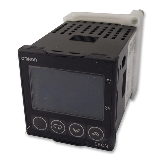
OMRON E5CN
©All Rights Reserved
2162869-1A
CHT6
1
1
3
1
1
-169
M
M
1
3
3
E5CN/ E5CN-H/ E5CN-HT
ES1B
JPN
©All Rights Reserved
E5CN/E5CN-H/E5CN-HT
Digital Controller
Communication
Event Input
Heater Burnout Alarm/Heater Overcurrent Detection Alarm
Heater Short Alarm (CT1/CT2)
Control Output 2 (Voltage Output)
External Power Supply for ES1B
Transfer output
EN
Thank you for purchasing the OMRON E5CN tempera-
ture controller. Read this manual carefully before using
the controller and always keep it close at hand while the
controller is in use.
OMRON CORPORATION
©All Rights Reserved
Transition between levels
Control will stop.
Displayed only for models
with communications.
Communication
setting level
Press
Power on
Press
:
(less than 1 second)
(less than
Hold
down
1 second).
for at least
3 seconds
Operation
Adjustment
Initial setting level
level
level
Hold
down
Input
Press
:
for at least
password
(less than
1 second
1 second).
(-169).
Hold
+ M down
Hold
+ M down
Advanced function
for at least 1 second
for at least 3 seconds
setting level
Control in progress
Protect level
Control stopped
Level change
Transition to Communication setting level
Press the
key for at least three seconds to move from the operation
level to the initial setting level; press the
key once again to move to
the communication setting level.
SP
0 3
m-sp
1
0.0 55.0
ct1
2
0.0 55.0
ct2
1
0.0 55.0
lcr1
2
0.0 55.0
lcr2
cmwt
ON OFF
1
0.0 55.0
ct1
0.0 50.0
1
hb1
0.0 55.0
1
oc1
2
0.0 55.0
ct2
0.0 50.0
2
hb2
0.0 55.0
oc2
2
0.0 55.0
1
lcr1
0.0 50.0
HS
1
hs1
2
0.0 55.0
lcr2
HS
2
0.0 50.0
hs2
0
sp-0
1
sp-1
2
sp-2
3
sp-3
SP
0 2
ev-m
1
0
ev-1
2
0
ev-2
psel
Compoway/F(Sysway),Modbus
u-no
0 99
bps
1.2 2.4 4.8 9.6 19.2 38.4 57.6
len
7 8
1 2
sbit
prty
0 99
sdwt
SP
ON OFF
mspu
HBA ON/OFF
hbu
ON OFF
hbl
ON OFF
hbh
0.1 50.0
HS
hsu
ON OFF
HS
hsl
ON OFF
HS
0.1 50.0
hsh
ocu
ON OFF
ocl
ON OFF
och
0.1 50.0
-500
E53-CN
N2
-H
-HT
E5CN/E5AN/E5EN
E5CN-HT/E5EN-HT/E5AN-HT
E5CN/E5AN/E5EN
E5CN-HT/E5EN-HT/E5AN-HT
m-sp
ct1
ct2
lcr1
lcr2
cmwt
ON OFF
ct1
hb1
oc1
ct2
hb2
oc2
lcr1
hs1
lcr2
hs2
sp-0
sp-1
sp-2
sp-3
ev-m
ev-1
ev-2
psel
Compoway/F(Sysway) Modbus
u-no
bps
len
sbit
prty
sdwt
mspu
ON OFF
hbu
ON OFF
ON OFF
hbl
hbh
ON OFF
hsu
ON OFF
hsl
hsh
ocu
ON OFF
ON OFF
ocl
och
-500
E53-CN**N2
-H
-HT
E5CN/AN/EN
E5CN-HT/E5AN-HT/E5EN-HT
E5CN/AN/EN
E5EN-HT
Options Settings List (Only parameters for option unit are listed.)
Level
Setting
Display
Multi-SP
0 to 3
m-sp
Operation
Heater current 1 value monitor
ct1
0.0 to 55.0
level
Heater current 2 value monitor
0.0 to 55.0
ct2
Leakage current 1 monitor
0.0 to 55.0
lcr1
Leakage current 2 monitor
0.0 to 55.0
lcr2
Communications writing
ON, OFF
cmwt
Adjustment
Heater current 1 value monitor
0.0 to 55.0
ct1
level
Heater burnout detection 1
hb1
0.0 to 50.0
Heater Overcurrent Detection 1
0.0 to 55.0
oc1
Heater current 2 value monitor
0.0 to 55.0
ct2
Heater burnout detection 2
0.0 to 50.0
hb2
Heater Overcurrent Detection 2
0.0 to 55.0
oc2
Leakage current 1 monitor
0.0 to 55.0
lcr1
HS alarm 1
0.0 to 50.0
hs1
Leakage current 2 monitor
lcr2
0.0 to 55.0
HS alarm 2
0.0 to 50.0
hs2
Set point 0
Set point lower limit to set point upper limit
sp-0
Set point 1
Set point lower limit to set point upper limit
sp-1
Set point lower limit to set point upper limit
Set point 2
sp-2
Set point lower limit to set point upper limit
Set point 3
sp-3
0 to 2
Number of multi-SP uses
ev-m
Initial setting
Event input 1 allocation
0 to 10
ev-1
level
Event input 2 allocation
0 to 10
ev-2
Protocol selection
Compoway/F(Sysway) Modbus
psel
Communi-
Unit No.
0 to 99
u-no
cations
Communications baud rate
1.2, 2.4, 4.8, 9.6, 19.2, 38.4,57.6
setting
bps
Data bits
level
7, 8
len
Stop bits
1, 2
sbit
Communications parity
None, even, odd
prty
Send wait time
0 to 99
sdwt
Multi-SP use
ON, OFF
mspu
Advanced
HBA ON/OFF
ON, OFF
function
hbu
setting
Heater burnout latch
ON, OFF
hbl
level
Heater burnout hysteresis
hbh
0.1 to 50.0
HS alarm use
hsu
ON, OFF
HS alarm latch
ON, OFF
hsl
HS alarm hysteresis
0.1 to 50.0
hsh
Heater Overcurrent Use
ON, OFF
ocu
Heater Overcurrent Latch
ON, OFF
ocl
Heater Overcurrent Hysteresis
0.1 to 50.0
och
• For -500 models, install the E53-CN
N2.
• Some settings are not displayed on models with a model number with an "-H" or "-HT" suffix.
• For detailed operating instructions, refer to the E5CN/E5AN/E5EN User's Manual, E5CN-H/E5EN-H/E5AN-H User's Manual, or
E5CN-HT/E5EN-HT/E5AN-HT User's Manual.
• For detailed communications specifications, refer to the E5CN/E5AN/E5EN Communications Manual, E5CN-H/E5EN-H/E5AN-H
Communications Manual, or E5CN-HT/E5EN-HT/E5AN-HT User's Manual.
0
NA
A
A
A
A
OFF
NA
A
0.0
A
A
A
0.0
A
A
A
50.0
A
A
50.0
A
0
EU
0
EU
0
EU
EU
0
NA
1
0
NA
NA
1
Compoway/F
NA
NA
1
kbps
9.6
7
Bits
2
Bits
NA
ms
20
OFF
NA
ON
NA
OFF
NA
0.1
A
NA
ON
NA
OFF
A
0.1
ON
NA
OFF
NA
0.1
A
E5CN-H/E5EN-H/E5AN-H
E5CN-H/E5EN-H/E5AN-H
A
A
A
A
OFF
A
A
A
A
A
A
A
A
A
A
EU
EU
EU
EU
Compoway/F
kbps
ms
OFF
ON
OFF
A
ON
OFF
A
ON
OFF
A
E5CN-H/E5AN-H/E5EN-H
E5CN-H/E5AN-H/E5EN-H
E5CN-HT/E5AN-HT/
Set value/monitor value
Default
Unit
0
NA
OFF
NA
0.0
0.0
50.0
50.0
0
EU
0
EU
0
EU
0
EU
1
NA
0
NA
1
NA
Compoway/F
NA
1
NA
9.6
kbps
7
Bits
2
Bits
Even
NA
20
ms
OFF
NA
ON
NA
OFF
NA
0.1
ON
NA
OFF
NA
0.1
ON
NA
OFF
NA
0.1
2
SP
40% AT
ON
1k
OFF
100k
ON
1.5V OFF
ON
7mA
/
HS
CT1/CT2
•
2
CT
•
•
10.0A
1A
10.0A
2.5A
0.1A 49.9A
•
0.0A
50.0A
ON
•
50.0A
ffff
CT E54 CT1
E54 CT3
•
RS-485 RS-232C
•
•
Compoway/F (Sysway)
Modbus
• E53-CNQ01N2 E53-CN01N2 E53-CNH01N2
2
•
:
12V 21mA
ES1B
•
12V 10
20mA
•
ES1B
–H
–HT
53-CNPHN2 E53-CNPBN2 E53-CNP03N2
• 4 20 mA
600 Ω
• E53-CNQFN2 E53-CNBFN2
–H
SP
ON
ON
1.5V
OFF
ON
7mA
SSR
CT1 CT2
CT
A
1A
10.0A
2.5A
0.1 49.9A
OFF
50A
ffff
3
2
RS-485 RS-232C
Compoway/F(Sysway) Modbus
Sysway
E53-CNQ01N2
–H
–HT
DC12V 21mA
ES1B
DC12V±10% 20mA
ES1B
E53-CNPHN2
E53-CNPBN2
E53-CNP03N2
–H
–HT
4-20mA
600Ω
E53-CNQFN2
E53-CNBFN2
Event input
Number of inputs
2 points max.
Auto/Manual, Invert Direct/Reverse Operation, SP Mode Switch, 100% AT Execute/
Functions
Cancel, 40% AT Execute/Cancel, Setting Change Enable/Disable, Communications
A
A
Write Enable/Disable, Alarm Latch Cancel, etc.
A
Contact input
ON 1kΩ max., OFF 100kΩ min.
A
Input specifications
ON residual voltage1.5V max. OFF leakage current 0.1mA max.
No-contact input
ON terminal current Approx. 7mA(short-circuit)
A
Heater Burnout Alarm/Heater Short Alarm (CT1/CT2)
A
Establishing a value for the detection current for Single phase Power
A
• Use the following formula to establish a value for the detection current:
A
Normal heater current value + Heater burnout current value
A
Detection setting =
A
• When more than one heater is connected to the CT, use the burnout current of the heater using
A
the smallest current as the burnout value. (If all the heaters use the same size current, use the
A
value applicable to one heater as the burnout value.)
A
• Ensure that the following conditions are satisfied:
A
Heaters of less than 10.0A: Normal heater current value - Heater burnout current value ≥ 1A
The detection function is unreliable for currents of less than 1A.
Heaters of 10.0A or more: Normal heater current value - Heater burnout current value ≥ 2.5A
The detection function is unreliable for currents of less than 2.5A.
• The detection current can be set to anything from 0.1 to 49.9A. Heater burnout will not be
detected if the detection current is set to 0.0 or 50.0. Setting the value to 0.0 will have the effect
of switching the heater burnout alarm off; setting the value to 50.0 will have the effect of
switching the alarm on.
• The aggregate of the heaters' normal current values should not be more than 50.0A. If the value
exceeds 55.0A, the "heater current monitor" parameter will show "ffff".
CTs: E54-CT1 or E54-CT3. (available separately)
Finding the Detection Current for 3-phase Power
• When using 3-phase power, Heater burnout or HS alarms is available by reading the current
from two locations. Refer to the User's Manual for details on wiring.
Communication (RS-485,RS-232C)
• The communications settings (e.g., communications speed) must be the same as those of the host computer.
• The following communications protocols are supported: CompoWay/F (Sysway) and Modbus.
Programmable models do not support the SYSWAY communications protocol.
• Use the E53-CNQ01N2, E53-CN01N2, or E53-CNH01N2 only for models with a model number with an "-H"
or "-HT" suffix. Otherwise, malfunction may result.
A
Control Output 2 (Voltage Output)
• Specifications: 12 VDC, 21 mA (with short-circuit protection circuit)
External Power Supply for ES1B
A
• Specifications:12 VDC 10% at 20mA (with short-circuit protection circuit)
*Consult your OMRON sales representative about using the ES1B Infrared Thermosensor's external power supply for
other purposes. Do not use the E53-CNPHN2, E53-CNPBN2, or E53-CNP03N2 for models with a model number with an
A
"-H" or "-HT" suffix that do not have an ES1B sensor input.
Transfer output
• 4 to 20 mA, Allowable load impedance: 600 Ω max., Resolution: Approx. 10,000
• Use the E53-CNQFN2 or E53-CNBFN2 only for models with a model number with an "-H" or "-HT" suffix.
Otherwise, malfunction may result.
100% AT
0.1mA
1A
2.5A
0.0A
50.0A
OFF
55.0A
HS
SYSWAY
–H
–HT
OMRON
ES1B
10,000
–HT
100%
40%
0.1mA
2
1A
2.5A
ON
55.0A
SSR
E53-CN01N2
E53-CNH01N2
ES1B
10000
–H
–HT
2
Advertisement
Table of Contents

Related Manuals for Omron E5CN


Summary of Contents for Omron E5CN
- Page 1 • Some settings are not displayed on models with a model number with an "-H" or "-HT" suffix. Transition to Communication setting level • For detailed operating instructions, refer to the E5CN/E5AN/E5EN User's Manual, E5CN-H/E5EN-H/E5AN-H User's Manual, or Press the key for at least three seconds to move from the operation •...
Need help?
Do you have a question about the E5CN and is the answer not in the manual?
Questions and answers