Omron E5CN-H Datasheet
Advanced digital temperature controller (48 x 48 mm)
Hide thumbs
Also See for E5CN-H:
- Communications manual (128 pages) ,
- Instruction manual (2 pages) ,
- User manual (374 pages)
Table of Contents
Advertisement
Advanced Digital Temperature Controller
E5CN-H
A New High-performance Controller: High Resolution, High Speed, and
High Input Accuracy.
With Logic Operations and preventive
maintenance functions.
• High-resolution display with 5 digits/0.01°C display in a compact
Controller (48 x 48 mm).
• High-speed sampling cycle of 60 ms.
• High Accuracy
Thermocouple/Pt input: ±0.1% of PV
Analog input: ±0.1% FS
• Universal inputs on all models (thermocouple, PT, analog) to handle
various sensors with one Controller.
• A PV/SV-status display function can be set to alternate
displaying the PV or SV and the status of the Temperature
Controller (auto/manual, RUN/STOP and alarms).
• Flexible contact outputs with logic operations (AND, OR, and delays)
set from the Support Software (CX-Thermo Ver. 4.0)
• Preventive maintenance for relays
using a Control Output ON/OFF Counter.
Main I/O Functions
Event Inputs
• None
• Two
Universal Sensor Inputs
• Universal thermocouple/Pt/analog
(current/voltage) inputs.
Indication Accuracy
• Thermocouple/Pt input: ±0.1% of PV
• Analog input: ±0.1% FS
Sampling Period and control update
• 60 ms
This data sheet is provided as a guideline for selecting products. Be sure to refer to the following user manuals for application precautions
and other information required for operation before attempting to use the product.
E5CN-H/E5AN-H/E5EN-H Digital Controllers User's Manual Advanced Type (Cat. No. H157)
E5CN-H/E5AN-H/E5EN-H Digital Controllers Communications Manual Advanced Type (Cat. No. H159)
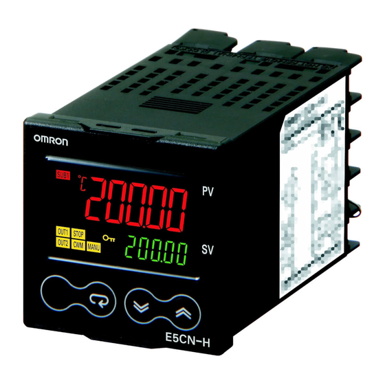
(48 x 48 mm)
E5CN-H
2-line Display: PV and SV
5-digit, 11 segment display
with high resolution of 0.01°C
Auxiliary Outputs
• Two
Control Output 2
• None
• Voltage output
(for driving SSR)
Control Output 1
• Relay output
• Voltage output (for driving SSR)
• Current output
• Linear voltage output
Advanced Digital Temperature Controller
48 × 48 mm
E5CN-H
Refer to Safety Precautions on page 18.
• Auto/manual switching
• Temperature Controller status display
• Simple program function
• Logic operations
• Control output ON/OFF count alarm
• PV change rate alarm
• Models optional with RS-485
or RS-232C communications
E5CN-H
1
Advertisement
Table of Contents

Related Manuals for Omron E5CN-H


Summary of Contents for Omron E5CN-H
- Page 1 • Current output • Linear voltage output This data sheet is provided as a guideline for selecting products. Be sure to refer to the following user manuals for application precautions and other information required for operation before attempting to use the product.
-
Page 2: Model Number Structure
2 auxiliary outputs E5CN-H Terminal block Universal input Advanced Type 2 control outputs 2 auxiliary outputs Note: All controllers can be used for Heating, Cooling and Heating & Cooling control. Model Number Structure Model Number Legend Controllers Option Units E53-CN@@N2 E5CN-H@2M@-500... -
Page 3: Option Units
E5CN-HC2MD-500 Linear voltage output E5CN-HV2MD-500 Note: Add power supply voltage to model to complete ordering code (ie. E5CN-HR2M-500 AC100-240 or E5CN-HR2MD-500 AC/DC24). Option Units One of the following Option Units can be mounted to provide the E5CN with additional functions. -
Page 4: Specifications
• Logic operation: Any of the following four patterns can be selected. The input status may be inverted. (A and B) or (C and D), (A or C) and (B or D), A or B or C or D, A and B and C and D (A, B, C, and D are four inputs.) -
Page 5: Input Ranges
Shaded settings are the default settings. The applicable standards for the input types are as follows: K, J, T, E, N, R, S, B: JIS C 1602-1995, IEC 584-1 JPt100: JIS C 1604-1989, JIS C 1606-1989 L: Fe-CuNi, DIN 43710-1985... -
Page 6: Alarm Outputs
Auxiliary outputs are allocated for alarms. ON delays and OFF delays (0 to 999 s) can also be specified. Note: For models with heater burnout, SSR failure, and heater overcurrent detection, alarm 1 will be an OR output of the alarm selected from the following alarm types and the alarms for heater burnout, SSR failure, and heater overcurrent. - Page 7 EN 61000-4-11 ✽1. The indication accuracy of K thermocouples in the −200 to 1300°C range, T and N thermocouples at a temperature of −100°C max., and U and L thermocouples at any temperatures is ±2°C ±1 digit max. The indication accuracy of the B thermocouple at a temperature of 400°C max. is not specified.
-
Page 8: Communications Specifications
✽1. For heater burnout alarms, the heater current will be measured Conversion Cable. when the control output is ON, and the output assigned to the alarm 1 function will turn ON if the heater current is lower than the Communications Specifications set value (i.e., heater burnout detection current value). -
Page 9: External Connections
• A voltage output (control output, for driving SSR) is not electrically insulated from the internal circuits. When using a grounding thermocouple, do not connect any of the control output terminals to ground. If the control output terminals are connected to ground, errors will occur in the measured temperature values as a result of leakage current. - Page 10 Waterproof Mounting Adapter Terminal Cover mounting space between Controllers.) Packing (Accessory) (E53-COV17) • To mount the Controller so that it is +0.6 (Accessory) (Accessory) waterproof, insert the waterproof packing onto the Controller. • When two or more Controllers are mounted, make sure that the surrounding Note: The terminal block cannot be removed.
-
Page 11: Terminal Cover
Order the Waterproof Packing separately if it becomes lost or Note: The E53-COV10 damaged. can not be used. The Waterproof Packing can be used to achieve an IP66 degree of protection. (Deterioration, shrinking, or hardening of the waterproof packing may occur depending on the operating environment. Therefore, periodic replacement is recommended to ensure the level of waterproofing specified in IP66. - Page 12 Adapter Y92F-45 Note: Use this Adapter when the panel has already been prepared for the E5B@. Fixture (Accessory) 69.6 to 77.6 72 × 72 67 × 67 Mounted to E5CN-H Panel (1 to 8 mm) 72 × 72 48 × 48 77.3 (to back of E5CN-H)
- Page 13 ✽3. From the manual control level, key operations can be used to move to the operation level only. Error Displays (Troubleshooting) When an error occurs, the No.1 display shows the error code. Take necessary measure according to the error code, referring the table below. Status at error No.1 display...
-
Page 14: Pid Setting Level
Advanced Type Some parameters are not displayed depending on the model of the Controller and parameter settings. For details, refer to the E5CN-H/E5AN-H/ Power ON E5EN-H Digital Controllers User's Manual Advanced Type (Cat. No. H157). Manual Control Level Operation Adjustment... -
Page 15: Manual Control Level
10 0. 0 only 1 s. mode. PV/MV Press the O and M Keys for at least 3 s. Press the O Key less than 1 s. Adjustment Level Operation Level Adjustment Level Process Value 25 . 0 r- s Display... -
Page 16: Initial Setting Level
The time taken to move to the protect level Displayed only for models with communications. Changes can be adjusted by changing the "Move to are effective after cycling power or after a software reset. protect level time" setting. in-h Scaling Upper Limit... -
Page 17: Advanced Function Setting Level
Level Level Communica- Initial Setting tions Setting Level Level Advanced Function Setting Level Press the O Key for at least 1 s. Advanced Function Setting Level spdp Input Shift Type alsp Alarm SP Selection istp "PV/SP" Display o-dp MV Display... -
Page 18: Safety Precautions
30 V r.m.s. and 42.4 V peak or 60 VDC. connected to the product. Malfunction may occur due to ✽2. A class 2 power supply is one tested and certified by UL as having noise in the cable. the current and voltage of the secondary output restricted to specific levels. -
Page 19: Measurement Accuracy
3. Mount the product so that it is horizontally level. use RAM write mode when frequently overwriting data during 4. If the measurement accuracy is low, check to see if input shift has communications or other operations. been set correctly. -
Page 20: Precautions When Wiring
0.29 to 0.39 N·m. Mounting the Terminal Cover E5CN Make sure that the “UP” mark is facing up, and then attach the E53- COV17 Terminal Cover to the holes on the top and bottom of the Temperature Controller. - Page 21 E5CN-H Advanced Digital Temperature Controller...
-
Page 22: Warranty And Application Considerations
CONTRACT, WARRANTY, NEGLIGENCE, OR STRICT LIABILITY. In no event shall the responsibility of OMRON for any act exceed the individual price of the product on which liability is asserted. IN NO EVENT SHALL OMRON BE RESPONSIBLE FOR WARRANTY, REPAIR, OR OTHER CLAIMS REGARDING THE...
Need help?
Do you have a question about the E5CN-H and is the answer not in the manual?
Questions and answers