Table of Contents
Advertisement
Digital Controller
The E5 K-T Programmable Type Digital
Controllers Expand the Variety of E5 K
Digital Controllers and are Available in
Three Sizes (1/4, 1/8, and 1/16 DIN).
E5AK-T/E5EK-T
1/4 DIN
This product was manufactured at OMRON Okayama. OMRON Okayama has obtained approvals from
international certification bodies for its quality system and environmental management system.
E5 K-T Series
1/8 DIN
Digital Controllers
. . . . . . . . . . . . . . . . . . . . . . . . . . . .
Common to Both Controllers
. . . . . . . . . . . . . . . . . . . . . . . . . . . . .
. . . . . . . . . . . . . . . . . . . . . . . . . .
Contents
. . . . . . . . . . . . . . . . . . . . .
. . . . . . . . . . . . . . . . . . . . . . . . .
. . . . . . . . . . . . . . . .
. . . . . . . . . . . . . . . . .
. . . . . . . . . . . . . . . . .
. . . . . . . . . . . . . . . . . . . . . . . .
. . . . . . . . . . . . . . . . . . . . . . . .
E5 K-T
E5CK-T
1/16 DIN
3
9
13
18
20
29
30
32
38
39
C
R
1
Advertisement
Table of Contents

Related Manuals for Omron E5EK-T


Summary of Contents for Omron E5EK-T
-
Page 1: Table Of Contents
Digital Controllers and are Available in Three Sizes (1/4, 1/8, and 1/16 DIN). This product was manufactured at OMRON Okayama. OMRON Okayama has obtained approvals from international certification bodies for its quality system and environmental management system. E5 K-T Series... - Page 2 E5 K-T E5 K-T Compact and Easy-to-use Controllers Programming is as easy as following the steps below. Program can be set in pattern 0 according to the following proce- 4. Set the target value to “50.” dure. Step 1 Step 2 Step 3 Target value Up key...
-
Page 3: E5Ak-T/E5Ek-T
Digital Controller E5AK-T/E5EK-T Advanced Programmable Digital Controllers Ideal for Worldwide Use Offers up to eight patterns of simple programming control (16 steps per pattern). Modular structure, one-stock type High-accuracy: 100-ms sampling (for analog input) Conforms to international EMC and safety standards. - Page 4 E5AK-T/E5EK-T E5AK-T/E5EK-T Description Model Specification Output Unit E53-R Relay E53-S E53-Q Pulse (NPN) 12 VDC at 40 mA max. E53-Q3 Pulse (NPN) 24 VDC at 20 mA max. E53-Q4 Pulse (PNP) 24 VDC at 20 mA max. Linear (4 to 20 mA) under a load of 600 Ω max.
- Page 5 E5AK-T/E5EK-T E5AK-T/E5EK-T Current/Voltage Input (switch selectable) Current input Voltage input 4 to 20 mA 0 to 20 mA 1 to 5 V 0 to 5 V 0 to 10 V Range One of following ranges depending on results of scaling –1999 to 9999...
- Page 6 E5AK-T/E5EK-T E5AK-T/E5EK-T Characteristics Indication accuracy (see note) Thermocouple: ( 0.3% of indication value or 1 C, whichever greater) 1 digit max. Platinum resistance thermometer: ( 0.2% of indication value or 0.8 C, whichever greater) 1 digit max. Analog input: 0.2% FS 1 digit max.
- Page 7 E5AK-T/E5EK-T E5AK-T/E5EK-T Output Unit Ratings and Characteristics Model Specifications E53-R Relay output 5 A at 250 VAC (resistive load) E53-S SSR output 1 A at 75 to 250 VAC (resistive load) E53-Q Voltage output NPN: 40 mA at 12 VDC...
- Page 8 E5AK-T/E5EK-T E5AK-T/E5EK-T Nomenclature E5AK Display 1 Pattern Number Displays the process value or Indicates the pattern number. parameter code. Program Status Indicators Display 2 The top indicator indicates the rising Displays the present SP, manip- step, the middle indicator indicates the...
-
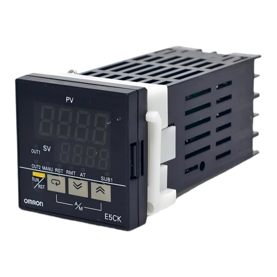
Page 9: E5Ck-T
Digital Controller E5CK-T Advanced, Compact Programmable Digital Controllers Ideal for Worldwide Offers up to four patterns of simple programming control (16 steps per pattern). IP66/NEMA4 (indoor use) front face. Modular structure, one-stock type. Heat/Cool control. Serial communications (RS-232C and RS-485). Temperature and analog inputs. - Page 10 E5CK-T E5CK-T Temperature Ranges Platinum Resistance Thermometer Input (switch selectable) JPt100 Pt100 Range –199.9 to 650.0 –199.9 to 650.0 –199.9 to 999.9 –199.9 to 999.9 Resolution ( C/ F) (main setting and alarm) Thermocouple Input (switch PLII selectable) (see note) Range –200 0.0 to...
- Page 11 E5CK-T E5CK-T Characteristics Indication accuracy (see note 1) Thermocouple: ( 0.3% of indication value or 1 C, whichever greater) 1 digit max. Platinum resistance thermometer: ( 0.2% of indication value or 0.8 C, whichever greater) 1 digit max. Analog input: 0.2% FS 1 digit max. Hysteresis 0.01% to 99.99% FS (in units of 0.01% FS) Proportional band (P)
- Page 12 E5CK-T E5CK-T Output Unit Ratings and Characteristics Model Control output 1/Control output 2 Output Type Specifications E53-R4R4 Relay / Relay Relay 250 VAC. 3 A Voltage (NPN) 12 VDC, 20 mA (with short-circuit protection) E53-Q4R4 Voltage (NPN) / Relay Voltage (PNP) 12 VDC, 20 mA (with short-circuit protection) E53-Q4HR4 Voltage (PNP) / Relay...
-
Page 13: Setup
E5jK-T E5jK-T Setup Note: Always turn OFF the power supply to the Digital Controller before changing any switch settings. Settings (E5AK/E5EK) On a standard model, set up the Output Units for control outputs 1 2. Insert the Output Unit for control output 1 into the socket and 2 before mounting the Controller. - Page 14 E5jK-T E5jK-T Mounting Setting Up the Terminal Cover 1. Insert the E5AK-T Controller into the mounting hole in the Fasten the Terminal Covers (E53-COV0809) to protect terminals. panel. E5AK-VV2-500 Controller is provided with Terminal Covers. 2. Fit the mounting bracket (accessory) into the fixing slots on Use E53-COV09 for terminals 1 to 10, and E53-COV08 for termi- the top and bottom of the rear case.
- Page 15 E5jK-T E5jK-T E5EK 2. Remove the power board in the direction of the arrow in the figure below. The power board is connected to the control Draw-out board by a connector at the center of the board. When drawing out the internal mechanism from the housing, pre- pare a Phillips screwdriver matched to the size of the screw on the lower part of the front panel.
- Page 16 Fasten the Terminal Covers (E53-COV0809) to protect terminals. Mounting E5AK-VV2-500 Controller is provided with Terminal Covers. 1. Insert the E5EK-T Controller into the mounting hole in the Use E53-COV09 for terminals 1 to 10, and E53-COV08 for termi- panel. nals 11 to 33.
- Page 17 Mounting 1. Insert the E5EK-T Controller into the mounting hole in the panel. 2. Draw out the internal mechanism towards you holding both 2. Push the adapter along the Controller body from the terminals sides of the front panel.
-
Page 18: Dimensions
E5jK-T E5jK-T Dimensions Note: All units are in millimeters unless otherwise indicated. E5AK Panel Cutouts 96 x 96 110 min. 120 min. Note: 1. Recommended panel thickness is 1 to 8 mm. 2. Maintain the specified vertical and horizontal mounting space between each Unit. Units must not be closely mounted vertically or horizontally. - Page 19 E5jK-T E5jK-T Accessories (Order Separately) Terminal Cover E53-COV0809 (E5AK) E53-COV08 (E5EK) (With rivet) (With rivet) E53-COV07 (With rivet) Current Transformer E54-CT1 E54-CT3 2.36 dia. 5.8 dia. 12 dia. 40x40 Two, M3 (depth: 4)
-
Page 20: Installation
E5jK-T E5jK-T Rubber Seal Installation Wiring Terminals Terminal Arrangement E5AK-T E5EK-T 100-240 VAC 100-240 VAC 24 VDC/AC 24 VDC/AC SOURCE SOURCE TRSF: Transfer output TRSF: Transfer output EV1/2: Event input EV1 to 4: Event input PTMR: Potentiometer PTMR: Potentiometer E5CK-T... - Page 21 E5jK-T E5jK-T Precautions when Wiring Use ducts to separate input leads and power lines in order to protect the Controller and its lines from external noise. Solderless terminals are recommended when wiring the Controller. Tighten the terminal screws using a torque no greater than 0.78 N m, or 8 kgf cm max. Take care not to tighten the terminal screws too tightly. Power Blocks The E5AK/E5EK has independent power supplies for each of the terminal blocks shown below.
- Page 22 E5jK-T E5jK-T Control Output Terminal numbers 7 and 8 are for control output 1 (OUT1), and terminal numbers 5 and 6 are for control output 2 (OUT2). The following dia- grams show the available Output Units and their internal equalizing circuits. With E53-Vjj Output Units, approx.
- Page 23 E5jK-T E5jK-T CT Input/Potentiometer When using the HBA function on the E5AK-AA2 Controller, connect CT input (CT) to terminal numbers 15 to 17. When monitoring the valve opening on the E5AK-PRR2 Controller, connect the potentiometer (PTMR) to terminal numbers 15 to 17. Connect each of these inputs as follows: 31 32 CT input...
- Page 24 Terminal numbers 18 to 20, 31 and 32 can be used only on Controllers with Communications Units (E53-AK01/02/03). For details on wiring, refer to Chapter 6, Using the Communications Function in the E5AK-T/E5EK-T/E5CK-T User’ s Manual (H88/H89/H90) . E5EK Wiring In the following wiring diagrams, the left side of the terminal numbers indicate the inside of the Controller.
- Page 25 E5jK-T E5jK-T Control Output Terminal numbers 7 and 8 are for control output 1 (OUT1), and terminal numbers 5 and 6 are for control output 2 (OUT2). The following dia- grams show the available Output Units and their internal equalizing circuits. With E53-Vjj Output Units, approx.
- Page 26 Potentiometer For details on CT inputs, refer to Appendix, About Current T ransformer in the E5AK-T/E5EK-T/E5CK-T User’ s Manual (H88/H89/H90) . For details on the potentiometer, refer to the Instruction Manual for the valve connected to the Controller. The variable resistance range is 100 Ω to 2.5 kΩ.
- Page 27 Communications Terminal numbers 18 to 22 can be used only on Controllers with Communications Units (E53-AK01/02/03). For details on wiring, refer to Chap- ter 6, Using the Communications Function in the E5AK-T/E5EK-T/E5CK-T User’ s Manual (H88/H89/H90) . E5CK Wiring Power Supply Input 100 to 240 VAC or 24 VAC/DC to terminal numbers 4 and 5 according to the specification.
- Page 28 E5jK-T E5jK-T Auxiliary Output 1 Terminal numbers 2 and 3 are for auxiliary output 1 (SUB1). The internal equalizing circuit for auxiliary output 1 is as follows: Relay specifications are as follows: SPST-NO, 250 VAC, 1 A Option Terminal numbers 1, 13, and 14 are valid only when the Option Unit is set in the Controller. The following four connections are possible depending on the model of the Option Unit.
-
Page 29: Setup Mode Operation
E5jK-T E5jK-T After Turning Power ON To previous column From previous column Determine the I/O specifications of the Digital Controller in setup mode. Control output 1 assignment (Not Setup Mode displayed by the E5jK-TPRR2) Control output 2 Power ON assignment (Not displayed by the E5jK-TPRR2) Output... -
Page 30: General Specification
E5jK-T E5jK-T Specifications Input Type Standard Models Assignment Set the code according to the following table. Default is “2: K1 ther- Control Output Auxiliary Output Destination Destination mocouple.” Platinum Resistance Thermometer Output Function Input type Input type Control output (heat) value (see note 1) JPt100... - Page 31 E5jK-T E5jK-T The LBA (loop break alarm) function is available when it is assigned as an output. The LBA function is not available when a memory or A/D converter error results. LBA is a function for determining that an error has occurred some- where on the control loop and outputting an alarm when the process value does not change with the manipulated variable at a maximum or minimum state.
-
Page 32: Parameter Operations
1 second min. Calibration mode Parameters and Menus Note: For more details on the functions of each part and display contents, refer to the E5AK-T/E5EK-T/E5CK-T User’s Manual (H88/H89/H90) . Protect Mode The protect function is for preventing unwanted modification of parameters and switching between run and reset operation or auto and manual operation. - Page 33 E5jK-T E5jK-T Level 0 Mode Set the Controller to this mode during normal operation. In this mode, you can change the set point and pattern during operation, and execute step operation (e.g. advance). You can only monitor (not change) the process value, step No., standby time, pattern elapsing time, pattern execution count, and manipulated variable.
- Page 34 E5jK-T E5jK-T Parameter Operation Refer to the E5AK-T/E5EK-T/E5CK-T User’ s Manual (H88/H89/H90) for each parameter and the calibration mode in detail. Refer to page 13 for the setting in detail. Level 0 Mode Protect Mode Under this mode, key operations are invalidated for the Auto/Manu- al and Run/Reset.
- Page 35 E5jK-T E5jK-T Program Mode Time Setting Method Pattern number Synchronized with with the pattern number of level 0 mode. Set the number of steps to be used beginning with step 0 (e.g., step 0 SP, step 0 time, step 1 SP, and step 1 time). The step target value can be set within a range between the Step number lower and upper target value limits.
- Page 36 E5jK-T E5jK-T Level 1 Mode Level 2 Mode Remote/Local Used for the AT Execute/Cancel communications function. Proportional Band Standby Time Available if the Controller is in 2-PID control. LBA Detection Time Integral Time Available when the LBA (loop break Available if the Controller is in 2-PID control. alarm) is assigned as an output.
- Page 37 E5jK-T E5jK-T Expansion Mode Option Mode Event Input Assignment 1 Available for the event input function. Set Point Upper Limit Event Input Assignment 2 Available for the event input function. Set Point Lower Limit Event Input Assignment 3 Available for the event input function. PID/ON/OFF (not displayed for control valve control) Event Input Assignment 4...
-
Page 38: Error Display
E5jK-T E5jK-T How to Use the Error Display When an error has occurred, the No.1 display alternately indicates error codes together with the current display item. This section describes how to check error codes on the display, and the actions that must be taken to remedy the problem. Input Error Meaning Input is in error. -
Page 39: Precautions
E5jK-T E5jK-T Precautions WARNING If there is a large power-generating peripheral device and any of its lines near the Controller, attach a surge suppressor or noise filter to Do not touch the terminals while the power is ON. the device to stop the noise affecting the Controller system. In par- This may cause an electric shock. - Page 40 Power supply INPUT LOAD ing SSR) for load – – Connectable Power SSR E5AK-T, E5EK-T Digital Controller with Voltage Output (12 VDC, 40 mA max.) E5CK Digital Controller with Voltage Output (12 VDC, 20 mA max.) See the following table.
- Page 41 E5jK-T E5jK-T...
- Page 42 E5jK-T E5jK-T...
- Page 43 E5jK-T E5jK-T...
- Page 44 To convert millimeters into inches, multiply by 0.03937. To convert grams into ounces, multiply by 0.03527. Cat. No. H087-E1-2 In the interest of product improvement, specifications are subject to change without notice. OMRON Corporation Supervisory Control Devices Division 28th Fl., Crystal Tower Bldg.,...
Need help?
Do you have a question about the E5EK-T and is the answer not in the manual?
Questions and answers