
Related Manuals for Kontron CP3002-RC


Summary of Contents for Kontron CP3002-RC
- Page 1 » User Guide « CP3002-RC/CP3002-RA 3U CompactPCI Processor Board based on the Intel® Core™ i7 Processor with the Intel® QM57 Chipset Doc. ID: 1039-3625, Rev. 1.0 October 8, 2010 If it’s embedded, it’s Kontron.
-
Page 2: Imprint
Disclaimer Copyright © 2010 Kontron AG. All rights reserved. All data is for information purposes only and not guaranteed for legal purposes. Information has been carefully checked and is believed to be accurate; however, no responsibility is assumed for inaccuracies. Kontron and the Kontron logo and all other trademarks or registered trademarks are the property of their respective own- ers and are recognized. -
Page 3: Table Of Contents
1.4.3 Board Layout .................. 1 - 7 1.5 Technical Specification ................1 - 8 1.6 Standards for the CP3002-RC .............. 1 - 12 1.7 Standards for the CP3002-RA ............... 1 - 13 1.8 Related Publications ................1 - 14 Functional Description ............2 - 3 2.1 Processor .................... - Page 4 ..........3 - 4 3.2 Initial Installation Procedures for the CP3002-RC 3.3 Standard Removal Procedures for the CP3002-RC ........3 - 6 3.4 Initial Installation Procedures for the CP3002-RA ........3 - 7 3.5 Standard Removal Procedures for the CP3002-RA ........3 - 8 Page iv ID 1039-3625, Rev.
- Page 5 CP3002-RC/CP3002-RA Preface 3.6 Hot Swap Procedures ................3 - 8 3.7 Installation of CP3002-RC/CP3002-RA Peripheral Devices ....3 - 8 3.7.1 SATA Flash Module Installation ............ 3 - 10 3.7.2 Rear I/O Device Installation ............3 - 10 3.8 Software Installation ................3 - 10 Configuration ................
- Page 6 Regulation ................5 - 5 5.2 Power Consumption ................5 - 6 5.2.1 Power Consumption of the CP3002-RC/CP3002-RA Accessories ..5 - 8 5.2.2 Power Consumption of the Gigabit Ethernet Controller ....5 - 8 5.3 Start-Up Currents of the CP3002-RC/CP3002-RA ........5 - 8 Thermal Considerations ............
-
Page 7: List Of Tables
Standards for the CP3002-RA ..............1 - 13 Related Publications ................1 - 14 Features of the Processor Supported on the CP3002-RC/CP3002-RA ..2 - 4 Debug LEDs’ Function ................2 - 7 POST Code Sequence ................2 - 8 POST Code Example ................ - Page 8 DC Operational Input Voltage Ranges ............5 - 3 CP3002-RC/-RA in EFI Shell ..............5 - 7 CP3002-RC/-RA with Win. XP and Processor and Graphics in Idle State.. 5 - 7 CP3002-RC/-RA with Win. XP and Typ. Proc. and Graph. Contr. Workload 5 - 7 CP3002-RC/-RA with Win.
- Page 9 CP3002-RC with SATA Flash Module ............3 - 9 CP3002-RA with SATA Flash Module ............3 - 9 Position of the Reference Points on the CP3002-RC ......6 - 6 CP3002-RA with i7-620LE, 2.0 GHz ............6 - 9 SATA Flash Module Layout (Bottom View) ..........A - 4 ID 1039-3625, Rev.
- Page 10 Preface CP3002-RC/CP3002-RA This page has been intentionally left blank. Page x ID 1039-3625, Rev. 1.0...
-
Page 11: Proprietary Note
Kontron without further notice. Trademarks Kontron, the PEP logo and, if occurring in this manual, “CXM” are trademarks owned by Kontron, Kaufbeuren (Germany). In addition, this document may include names, company logos and trademarks, which are registered trademarks and, therefore, proprietary to their respective owners. -
Page 12: Explanation Of Symbols
Preface CP3002-RC/CP3002-RA Explanation of Symbols Caution, Electric Shock! This symbol and title warn of hazards due to electrical shocks (> 60V) when touching products or parts of them. Failure to observe the pre- cautions indicated and/or prescribed by the law may endanger your life/health and/or result in damage to your material. -
Page 13: For Your Safety
However, the life expectancy of your product can be drastically reduced by improper treatment during unpacking and installation. Therefore, in the interest of your own safety and of the correct operation of your new Kontron product, you are requested to conform with the following guidelines. -
Page 14: General Instructions On Usage
CP3002-RC/CP3002-RA General Instructions on Usage In order to maintain Kontron’s product warranty, this product must not be altered or modified in any way. Changes or modifications to the device, which are not explicitly approved by Kontron and described in this manual or received from Kontron’s Technical Support as a special handling instruction, will void your warranty. -
Page 15: Two Year Warranty
As a result, the products are sold “as is,” and the responsibility to ensure their suitability for any given task remains that of the purchaser. In no event will Kontron be liable for direct, indirect or consequential damages resulting from the use of our hardware or software products, or documentation, even if Kontron were advised of the possibility of such claims prior to the purchase of the product or during any period since the date of its purchase. - Page 16 Preface CP3002-RC/CP3002-RA This page has been intentionally left blank. Page xvi ID 1039-3625, Rev. 1.0...
-
Page 17: Introduction
CP3002-RC/CP3002-RA Introduction Chapter Introduction ID 1039-3625, Rev. 1.0 Page 1 - 1... - Page 18 Introduction CP3002-RC/CP3002-RA This page has been intentionally left blank. Page 1 - 2 ID 1039-3625, Rev. 1.0...
-
Page 19: Board Overview
256 kB L2 cache and 4 MB L3 cache in a BGA package with 2.0 GHz frequency. The processor and the memory are soldered on the CP3002-RC/CP3002-RA which results in high- er Mean Time Between Failures (MTBF) and a significant improvement in cooling. -
Page 20: Board-Specific Information
1.3.1 Serial ATA Flash Module The CP3002-RC/CP3002-RA provides support for up to 32 GB of Serial ATA Flash memory in combination with an optional Serial ATA Flash module, which is connected to an onboard ex- tension connector. For further information concerning the Serial ATA Flash module, please re- fer to Appendix A. -
Page 21: Functional Block Diagram
CP3002-RC/CP3002-RA Introduction 1.4.1 Functional Block Diagram Figure 1-1: CP3002-RC/CP3002-RA Functional Block Diagram ID 1039-3625, Rev. 1.0 Page 1 - 5... -
Page 22: Cp3002-Ra Front Panel
Introduction CP3002-RC/CP3002-RA 1.4.2 CP3002-RA Front Panel Figure 1-2: CP3002-RA Front Panel Legend: Debug LEDs: DLED0 (red/green): Debug LED 0 + POST DLED1 (red/green): Debug LED 1 + POST DLED2 (red/green): Debug LED 2 + POST DLED3 (red/green): Debug LED 3 + POST Page 1 - 6 ID 1039-3625, Rev. -
Page 23: Board Layout
CP3002-RC/CP3002-RA Introduction 1.4.3 Board Layout Figure 1-3: CP3002-RC/CP3002-RA Board Layout – Top View DDR3 Memory Intel ® Core ™ i7 Contr. Intel ® QM57 GMCH SATA Flash Module Figure 1-4: CP3002-RC/CP3002-RA Board Layout – Bottom View DDR3 Memory DLED 0... -
Page 24: Technical Specification
DMI and FDI interfaces to the Intel® QM57 chipset • Two x8 PCI Express 2.0 ports operating at 2.5 GT/s • Please contact Kontron for further information concerning the suitability of other Intel processors for use with the CP3002-RC/CP3002-RA. Memory Main Memory: Up to 8 GB, dual-channel DDR3 SDRAM memory with ECC running at •... - Page 25 • Support for up to four peripheral slots (4x REQ/GNT signals) • Note ... To operate the CP3002-RC/CP3002-RA, 3U CompactPCI back- plane with maximum five slots and rear I/O support on the system slot is required. Rear I/O The following interfaces are routed to the rear I/O CompactPCI connector J2: 1 x COMA (RS-232 signaling) •...
- Page 26 (open interface) Operating Systems The board is offered with various Board Support Packages including Windows and Linux operating systems. For further information concerning the operating systems available for the CP3002-RC/CP3002-RA, please contact Kontron. Page 1 - 10 ID 1039-3625, Rev. 1.0...
- Page 27 When additional components are installed, refer to their opera- tional specifications as this will influence the operational and stor- age temperature of the CP3002-RC/CP3002-RA. Back-up Voltage A back-up voltage input for the RTC can be connected via the rear I/O connec- tor J2.
-
Page 28: Standards For The Cp3002-Rc
Customers desiring to perform further environmental testing of Kontron prod- ucts must contact Kontron for assistance prior to performing any such testing. This is necessary, as it is possible that environmental testing can be destructive when not performed in accordance with the applicable specifications. -
Page 29: Standards For The Cp3002-Ra
Customers desiring to perform further environmental testing of Kontron prod- ucts must contact Kontron for assistance prior to performing any such testing. This is necessary, as it is possible that environmental testing can be destructive when not performed in accordance with the applicable specifications. -
Page 30: Related Publications
Introduction CP3002-RC/CP3002-RA Related Publications The following publications contain information relating to the CP3002-RC/CP3002-RA. Table 1-4: Related Publications PRODUCT PUBLICATION CompactPCI Systems and CompactPCI Specification PICMG 2.0, Rev. 3.0 Boards Kontron CompactPCI Backplane Manual, ID 24229 Platform Firmware Unified Extensible Firmware Interface (uEFI) Specification, Version 2.1... -
Page 31: Functional Description
CP3002-RC/CP3002-RA Functional Description Chapter Functional Description ID 1039-3625, Rev. 1.0 Page 2 - 1... - Page 32 Functional Description CP3002-RC/CP3002-RA This page has been intentionally left blank. Page 2 - 2 ID 1039-3625, Rev. 1.0...
-
Page 33: Processor
This is achieved by switching the bus ratios, the core operat- ing voltage, and the core processor speeds without resetting the system. The Intel® Core™ i7 processor used on the CP3002-RC/CP3002-RA has the following multi- level cache structure: •... -
Page 34: Memory
Intel® QM57 Express Chipset The CP3002-RC/CP3002-RA is equipped with the mobile Intel® QM57 Express Chipset, a highly integrated platform controller hub (PCH) with the following features: • Two x4 or eight x1 PCI Express 2.0 ports operating at 2.5 GT/s (only one x1 PCI Express port is used) •... -
Page 35: Timer
• The Intel® QM57 chipset integrates eight high-precision event timers. Watchdog Timer The CP3002-RC/CP3002-RA provides a Watchdog timer that is programmable for a timeout period ranging from 125 ms to 4096 s in 16 steps. Failure to trigger the Watchdog timer in time results in a system reset or an interrupt. -
Page 36: Flash Memory
Flash module. 2.8.1 SPI FLASH for uEFI BIOS The CP3002-RC/CP3002-RA provides two SPI Flash chips (2 x 8 MB) for redundant uEFI BIOS. The fail-over mechanism for the uEFI BIOS recovery can be controlled via the jumper JP4. The SPI Flash includes a hardware write protection option, which can be configured via the uEFI BIOS. -
Page 37: Board Interfaces
2.10 Board Interfaces 2.10.1 Front Panel LEDs The CP3002-RC/CP3002-RA is equipped with four Debug LEDs that can be configured via two onboard registers (see Chapter 4.3.14, “Debug LED Configuration Register” and Chapter 4.3.15, "Debug LED Control Register"). Table 2-2: Debug LEDs’ Function... -
Page 38: Usb Interfaces
2.10.2 USB Interfaces The CP3002-RC/CP3002-RA supports two USB 2.0 ports on the rear I/O. Both ports are high- speed, full-speed, and low-speed capable. Note ... The USB host interfaces can be used with maximum 500 mA continuous load current as specified in the Universal Serial Bus Specification, Revision 2.0. -
Page 39: Integrated Graphics Controller
2.10.4 Serial Ports The CP3002-RC/CP3002-RA provides two serial ports, COMA (RS-232) and COMB (RS-232/ RS-422), both available on the rear I/O. COMA and COMB are fully compatible with the 16550 controller. The rear I/O COMA port in- cludes a complete set of handshaking and modem control signals. -
Page 40: Gigabit Ethernet Interfaces
2.10.6 Serial ATA Interface The CP3002-RC/CP3002-RA provides three SATA I (1.5 Gbit/sec) and SATA II (3.0 Gbit/sec) compliant interfaces with RAID support (0/1/5). One interface is used for the SATA Flash mod- ule and two SATA interfaces are available only on the rear I/O. -
Page 41: Compactpci Bus Interface
I/O configured board in a backplane without rear I/O support. Fail- ure to comply with the above will result in damage to your board. The CP3002-RC/CP3002-RA is not hot-swappable but supports the addition or removal of oth- er boards whilst in a powered-up state. -
Page 42: 2.10.10.1 Compactpci Connectors J1 And J2
CompactPCI backplane connectors support guide lugs to ensure a correct polarized mating (3.3 V or 5 V V(I/O) coding). The CP3002-RC/CP3002-RA supports universal (3.3 V and 5 V) PCI V(I/O) signaling voltages with one common termination resistor configuration. Therefore, the CP3002- RC/CP3002-RA can be inserted in both, 3.3 V and 5 V... -
Page 43: 2.10.10.3 Compactpci Connectors J1 And J2 Pinouts
CP3002-RC/CP3002-RA Functional Description 2.10.10.3 CompactPCI Connectors J1 and J2 Pinouts The CP3002-RC/CP3002-RA is provided with two 2 mm x 2 mm pitch female CompactPCI bus connectors, J1 and J2. Table 2-5: CompactPCI Bus Connector J1 System Controller Slot Pinout ROW Z... -
Page 44: Rear I/O Compactpci Bus Connector J2 Pinout
Functional Description CP3002-RC/CP3002-RA Table 2-6: Rear I/O CompactPCI Bus Connector J2 Pinout ROW Z ROW A ROW B ROW C ROW D ROW E ROW F GPI4 USB1+ USB0+ USB1_PWR_5V GPO1 USB1- USB0- USB0_PWR_5V Back-up 3.3V GPI2 3.3V IPC_DA+ IPC_DA-... -
Page 45: 2.10.10.4 Rear I/O Pin Description
CP3002-RC/CP3002-RA Functional Description 2.10.10.4 Rear I/O Pin Description Serial Ports The CP3002-RC/CP3002-RA provides two serial ports, COMA (RS-232) and COMB (RS-232/ RS-422), both available on the rear I/O CompactPCI connector J2. Table 2-7: COMA and COMB Signal Description PIN on J2... -
Page 46: Gigabit Ethernet Signal Description
Functional Description CP3002-RC/CP3002-RA Ethernet Interfaces The CP3002-RC/CP3002-RA provides four 10Base-T/100Base-TX/1000Base-T Ethernet interfaces on the rear I/O CompactPCI connector J2. Table 2-8: Gigabit Ethernet Signal Description PIN on J2 SIGNAL FUNCTION DRIVEN BY SIGNALING VOLTAGE IPA_DA+ Media-dependent interface port A Bidirectional... -
Page 47: Serial Ata Signal Description
Bidirectional Differential USB1_PWR_5V USB power supply 5 V port 1 CP3002-RC/-RA 5 V VGA Interface The CP3002-RC/CP3002-RA provides one VGA analog port on the rear I/O CompactPCI con- nector J2. Table 2-11: VGA Signal Description PIN on J2 SIGNAL FUNCTION... -
Page 48: Compactpci Grounding Configuration
The GPI signals tolerate only 3.3 V signaling and the inputs have internal pull- up resistors. Power Signals The CP3002-RC/CP3002-RA provides three power signals on the rear I/O CompactPCI con- nector J2. Table 2-13: Power Signal Description PIN on J2... -
Page 49: Installation
CP3002-RC/CP3002-RA Installation Chapter Installation ID 1039-3625, Rev. 1.0 Page 3 - 1... - Page 50 Installation CP3002-RC/CP3002-RA This page has been intentionally left blank. Page 3 - 2 ID 1039-3625, Rev. 1.0...
-
Page 51: Safety Requirements
Installation Installation The CP3002-RC/CP3002-RA has been designed for easy installation. However, the following standard precautions, installation procedures, and general information must be observed to en- sure proper installation and to preclude damage to the board, other system components, or in- jury to personnel. -
Page 52: Initial Installation Procedures For The Cp3002-Rc
Installation CP3002-RC/CP3002-RA Initial Installation Procedures for the CP3002-RC The following procedures are applicable only for the initial installation of the CP3002-RC in a system. Procedures for standard removal of the CP3002-RC are found in their respective chap- ters. Warning! To operate the CP3002-RC, 3U CompactPCI backplane with maximum five slots and rear I/O support on the system slot is required. - Page 53 2.5 mm hex socket head. The recommended torque value is 0.8 N-m (115 oz-in). The CP3002-RC is now ready for initial operation. For operation of the CP3002-RC, refer to the appropriate CP3002-RC-specific software, application, and system docu- mentation.
-
Page 54: Standard Removal Procedures For The Cp3002-Rc
Warning! Care must be taken when applying the procedures below to ensure that neither the CP3002-RC nor system boards are physically damaged by the application of these procedures. 2. Ensure that no power is applied to the system before proceeding. -
Page 55: Initial Installation Procedures For The Cp3002-Ra
CP3002-RC/CP3002-RA Installation Initial Installation Procedures for the CP3002-RA The following procedures are applicable only for the initial installation of the CP3002-RA in a system. Procedures for standard removal operations are found in their respective chapters. To perform an initial installation of the CP3002-RA in a system proceed as follows: 1. -
Page 56: Standard Removal Procedures For The Cp3002-Ra
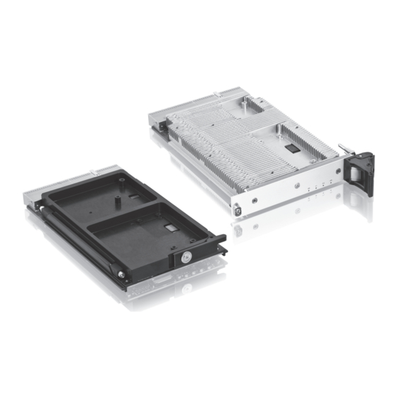
Installation of CP3002-RC/CP3002-RA Peripheral Devices The CP3002-RC/CP3002-RA is designed to accommodate a Serial ATA Flash module. The following figure shows the placement of the SATA Flash module on the CP3002-RC and the CP3002-RA. Page 3 - 8... -
Page 57: Cp3002-Rc With Sata Flash Module
CP3002-RC/CP3002-RA Installation Figure 3-1: CP3002-RC with SATA Flash Module SATA Flash Module Figure 3-2: CP3002-RA with SATA Flash Module SATA Flash Module ID 1039-3625, Rev. 1.0 Page 3 - 9... -
Page 58: Sata Flash Module Installation
The following sections provide information regarding installation aspects of peripheral devices. 3.7.1 SATA Flash Module Installation A SATA Flash module may be connected to the CP3002-RC/CP3002-RA via the onboard con- nector, J3. This optionally available module must be physically installed on the CP3002-RC/CP3002-RA prior to installation of the CP3002-RC/CP3002-RA in a system. -
Page 59: Configuration
CP3002-RC/CP3002-RA Configuration Chapter Configuration ID 1039-3625, Rev. 1.0 Page 4 - 1... - Page 60 Configuration CP3002-RC/CP3002-RA This page has been intentionally left blank. Page 4 - 2 ID 1039-3625, Rev. 1.0...
-
Page 61: Jumper Description
Configuration Jumper Description The CP3002-RC/CP3002-RA has four jumpers JP1, JP2, JP3 and JP4. JP1 and JP2 are used to activate the bus termination for COMB (RS-422). JP3 is used for clearing the uEFI BIOS boot settings. JP4 is used for uEFI BIOS boot configuration. For the location of the jumpers, refer to Figure 1-4. -
Page 62: I/O Address Map
Configuration CP3002-RC/CP3002-RA The default setting is indicated by using italic bold. I/O Address Map The following table indicates the CP3002-RC/CP3002-RA-specific registers. Table 4-5: I/O Address Map ADDRESS DEVICE 0x080 - uEFI BIOS POST Code Low Byte Register (POSTL) 0x081 uEFI BIOS POST Code High Byte Register (POSTH) -
Page 63: Cp3002-Rc/Cp3002-Ra-Specific Registers
Configuration CP3002-RC/CP3002-RA-Specific Registers The following registers are special registers which the CP3002-RC/CP3002-RA uses to watch the onboard hardware special features and the CompactPCI control signals. Normally, only the system uEFI BIOS uses these registers, but they are documented here for application use as required. -
Page 64: Status Register 1 (Stat1)
Configuration CP3002-RC/CP3002-RA 4.3.2 Status Register 1 (STAT1) The Status Register 1 holds board-specific status information. Table 4-7: Status Register 1 (STAT1) REGISTER NAME STATUS REGISTER 1 (STAT1) ADDRESS 0x281 RESET NAME DESCRIPTION ACCESS VALUE C66EN CPCI PCI speed (M66EN signal):... -
Page 65: Control Register 0 (Ctrl0)
CP3002-RC/CP3002-RA Configuration 4.3.3 Control Register 0 (CTRL0) The Control Register 0 holds one bit for specifying the boot Flash to be updated. Table 4-8: Control Register 0 (CTRL0) REGISTER NAME CONTROL REGISTER 0 (CTRL0) ADDRESS 0x282 RESET NAME DESCRIPTION ACCESS... -
Page 66: Device Protection Register (Dprot)
Configuration CP3002-RC/CP3002-RA 4.3.5 Device Protection Register (DPROT) The Device Protection Register holds the write protect signals for Flash devices. Table 4-10: Device Protection Register (DPROT) REGISTER NAME DEVICE PROTECTION REGISTER (DPROT) ADDRESS 0x284 RESET NAME DESCRIPTION ACCESS VALUE 7 - 3 Res. -
Page 67: Reset Status Register (Rstat)
CP3002-RC/CP3002-RA Configuration 4.3.6 Reset Status Register (RSTAT) The Reset Status Register is used to determine the host’s reset source. Table 4-11: Reset Status Register (RSTAT) REGISTER NAME RESET STATUS REGISTER (RSTAT) ADDRESS 0x285 RESET NAME DESCRIPTION ACCESS VALUE PORS Power-on reset status:... -
Page 68: Board Interrupt Configuration Register (Bicfg)
Configuration CP3002-RC/CP3002-RA 4.3.7 Board Interrupt Configuration Register (BICFG) The Board Interrupt Configuration Register holds a series of bits defining the interrupt routing. Table 4-12: Board Interrupt Configuration Register (BICFG) REGISTER NAME BOARD INTERRUPT CONFIGURATION REGISTER (BICFG) ADDRESS 0x286 RESET NAME... -
Page 69: Status Register 2 (Stat2)
4.3.9 Board ID High Byte Register (BIDH) Each Kontron board is provided with a unique 16-bit board-type identifier in the form of a hexadecimal number. The Board ID High Byte Register is located in the address 0x288. The Board ID Low Byte Register is located in the address 0x28D. -
Page 70: Geographic Addressing Register (Geoad)
Configuration CP3002-RC/CP3002-RA 4.3.11 Geographic Addressing Register (GEOAD) This register holds the CompactPCI geographic address. Table 4-16: Geographic Addressing Register (GEOAD) REGISTER NAME GEOGRAPHIC ADDRESSING REGISTER (GEOAD) ADDRESS 0x28A RESET NAME DESCRIPTION ACCESS VALUE 7 - 5 Res. Reserved 4 - 0... -
Page 71: Watchdog Timer Control Register (Wtim)
4.3.12 Watchdog Timer Control Register (WTIM) The CP3002-RC/CP3002-RA has one Watchdog timer provided with a programmable timeout ranging from 125 msec to 4096 sec. Failure to strobe the Watchdog timer within a set time period results in a system reset or an interrupt. The interrupt mode can be configured via the Board Interrupt Configuration Register (0x286). -
Page 72: Watchdog Timer Control Register (Wtim)
Configuration CP3002-RC/CP3002-RA Table 4-17: Watchdog Timer Control Register (WTIM) REGISTER NAME WATCHDOG TIMER CONTROL REGISTER (WTIM) ADDRESS 0x28C RESET NAME DESCRIPTION ACCESS VALUE Watchdog timer expired status bit 0 = Watchdog timer has not expired 1 = Watchdog timer has expired. -
Page 73: Board Id Low Byte Register (Bidl)
4.3.13 Board ID Low Byte Register (BIDL) Each Kontron board is provided with a unique 16-bit board-type identifier in the form of a hexadecimal number. The Board ID Low Byte Register is located in the address 0x28D. The Board ID High Byte Register is located in the address 0x288. -
Page 74: Debug Led Configuration Register (Dlcfg)
Configuration CP3002-RC/CP3002-RA 4.3.14 Debug LED Configuration Register (DLCFG) The Debug LED Configuration Register holds a series of bits defining the onboard configuration of the onboard debug LEDs (DLED 0..3). For the location of the debug LEDs, refer to Figure 1-4. -
Page 75: Debug Led Control Register (Dlctrl)
CP3002-RC/CP3002-RA Configuration 4.3.15 Debug LED Control Register (DLCTRL) This register is used to switch on and off the Debug LEDs. Table 4-20: Debug LED Control Register (LCTRL) REGISTER NAME DEBUG LED CONTROL REGISTER (DLCTRL) ADDRESS 0x291 RESET NAME DESCRIPTION ACCESS... -
Page 76: General Purpose Output Register (Gpout)
Configuration CP3002-RC/CP3002-RA 4.3.16 General Purpose Output Register (GPOUT) This register is used to control the general purpose output signals on the rear I/O CompactPCI connector J2. Table 4-21: General Purpose Output Register (GPOUT) REGISTER NAME GENERAL PURPOSE OUTPUT REGISTER (GPOUT) -
Page 77: Power Considerations
CP3002-RC/CP3002-RA Power Considerations Chapter Power Considerations ID 1039-3625, Rev. 1.0 Page 5 - 1... - Page 78 Power Considerations CP3002-RC/CP3002-RA This page has been intentionally left blank. Page 5 - 2 ID 1039-3625, Rev. 1.0...
-
Page 79: System Power
Still it is necessary to observe certain criteria essential for application stability and reliability. The table below indicates the absolute maximum input voltage ratings that must not be exceed- ed. Power supplies to be used with the CP3002-RC/CP3002-RA should be carefully tested to ensure compliance with these ratings. Table 5-1:... -
Page 80: Backplane
5.1.3 Power Supply Units Power supplies for the CP3002-RC/CP3002-RA must be specified with enough reserve for the remaining system consumption. In order to guarantee a stable functionality of the system, it is recommended to provide more power than the system requires. An industrial power supply unit should be able to provide at least twice as much power as the entire system requires. -
Page 81: Regulation
For example, if the 5 V begins to decrease, all other input voltages must decrease accordingly. This is required in order to preclude cross currents within the CP3002-RC/CP3002-RA. Failure to comply with above may result in damage to the board or improper system operation. -
Page 82: Power Consumption
These values are unlikely to be reached in real applications. The following tables indicate the power consumption of the CP3002-RC/CP3002-RA with 4 GB DDR3 SDRAM in dual-channel mode. The measurements were made with the CP3002-RC/ CP3002-RA in EFI Shell mode as well as with the Windows®... -
Page 83: Cp3002-Rc/-Ra In Efi Shell
Intel® Core™ i7-620LE (LV) 2.0 GHz (typ.) 18.0 W 3.3 V 7.0 W Total 25.0 W Table 5-4: CP3002-RC/-RA with Win. XP and Processor and Graphics in Idle State POWER Intel® Core™ i7-620LE (LV) 2.0 GHz (typ.) 4.0 W 3.3 V 7.0 W Total 11.0 W... -
Page 84: Power Consumption Of The Cp3002-Rc/Cp3002-Ra Accessories
Intel® 82580EB, four 1000Base-T Ethernet ports plugged — approx. 2.0 W Start-Up Currents of the CP3002-RC/CP3002-RA The following table indicates the basic start-up currents of the CP3002-RC/CP3002-RA during the first 2-3 seconds after power has been applied (power-on). Table 5-9: Start-Up Currents of the CP3002-RC/CP3002-RA POWER Intel®... -
Page 85: Thermal Considerations
CP3002-RC/CP3002-RA Thermal Considerations Chapter Thermal Considerations ID 1039-3625, Rev. 1.0 Page 6 - 1... - Page 86 Thermal Considerations CP3002-RC/CP3002-RA This page has been intentionally left blank. Page 6 - 2 ID 1039-3625, Rev. 1.0...
-
Page 87: Board Internal Thermal Monitoring
Board Internal Thermal Monitoring To ensure optimal operation and long-term reliability of the CP3002-RC/CP3002-RA, all on- board components must remain within the maximum temperature specifications. The most crit- ical component on the CP3002-RC/CP3002-RA is the processor. Operating the CP3002-RC/ CP3002-RA above the maximum operating limits will result in permanent damage to the board. -
Page 88: Adaptive Thermal Monitor
Thermal Considerations CP3002-RC/CP3002-RA 6.2.2 Adaptive Thermal Monitor The Adaptive Thermal Monitor feature reduces the processor power consumption and the tem- perature when the processor silicon exceeds the Thermal Control Circuit (TCC) activation tem- perature until the processor operates at or below its maximum operating temperature. The temperature at which the Adaptive Thermal Monitor activates the Thermal Control Circuit is not user-configurable. -
Page 89: Catastrophic Cooling Failure Sensor
Second, they are the primary mechanism for conduction of heat from the board to the system chassis. Cooling of the CP3002-RC is a function of the system chassis which must provide adequate conduction cooling capability. To determine cooling performance, the board temperature can be measured at the reference point indicated in the figure below. -
Page 90: Maximum Reference Point Temperature At 105°C Cpu Die Temperature
Warning! As Kontron assumes no responsibility for any damage to the CP3002-RC or other equipment resulting from overheating of the CPU, it is highly recom- mended that system integrators as well as end users confirm that the opera-... -
Page 91: External Thermal Regulation Of The Cp3002-Ra
An airflow of 2.0 m/s is a typical value for a standard Kontron ASM rack. For other racks or housings the available airflow will differ. The maximum ambient operating temperature must be recalculated and/or measured for such environments. - Page 92 Thermal Considerations CP3002-RC/CP3002-RA Thermal characteristic curves • Thermal characteristic curve of the CP3002-RA with typical processor and graphics controller workload This load complies with the typical processor and graphics controller workload indicat- ed in Chapter 5.2, “Power Consumption”, Table 5-5.
-
Page 93: Operational Limits For The Cp3002-Ra
CP3002-RC/CP3002-RA must also be considered. Devices such as SATA Flash modules which are directly attached to the CP3002-RC/CP3002-RA must also be capable of being op- erated at the temperatures foreseen for the application. It may very well be necessary to revise system requirements to comply with operational environment conditions. - Page 94 Thermal Considerations CP3002-RC/CP3002-RA This page has been intentionally left blank. Page 6 - 10 ID 1039-3625, Rev. 1.0...
-
Page 95: Sata Flash Module
CP3002-RC/CP3002-RA SATA Flash Module Appendix SATA Flash Module ID 1039-3625, Rev. 1.0 Page A - 1... - Page 96 SATA Flash Module CP3002-RC/CP3002-RA This page has been intentionally left blank. Page A - 2 ID 1039-3625, Rev. 1.0...
-
Page 97: Technical Specifications
SATA Flash Module SATA Flash Module The CP3002-RC/CP3002-RA provides an optional SATA Flash module with up to 32 GB NAND Flash memory. The SATA Flash module is connected to the CP3002-RC/CP3002-RA via the board-to-board connectors J3 located on the CP3002-RC/CP3002-RA and J1 located on the SATA Flash module. -
Page 98: Sata Flash Module Layout
SATA Flash Module CP3002-RC/CP3002-RA SATA Flash Module Layout The SATA Flash module includes one board-to-board connector, J1, for connection to the CP3002-RC/CP3002-RA. Figure A-1: SATA Flash Module Layout (Bottom View) NAND Flash NAND Flash Page A - 4 ID 1039-3625, Rev. 1.0...
Need help?
Do you have a question about the CP3002-RC and is the answer not in the manual?
Questions and answers