Table of Contents
Advertisement
Quick Links
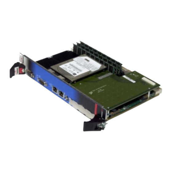
cPCI- DMXP64GX
®
6U CompactPCI
64-bit Peripheral Processor
Technical Reference Manual
Version 1.2
February 2003
Note: The latest releases of the Technical Reference Manuals are available at:
ftp://ftp.kontron.ca/support/Product_manuals/
Ref. : M6008_TECH
NOTE :
This manual is for reference purpose only.
Reproduction in whole or in part is authorized
provided Kontron Inc. is cited as the original
source.
Advertisement
Table of Contents

Related Manuals for Kontron cPCI-DMXP64GX


Summary of Contents for Kontron cPCI-DMXP64GX
- Page 1 Note: The latest releases of the Technical Reference Manuals are available at: ftp://ftp.kontron.ca/support/Product_manuals/ Ref. : M6008_TECH NOTE : This manual is for reference purpose only. Reproduction in whole or in part is authorized provided Kontron Inc. is cited as the original source.
- Page 2 This document may contain information or refer to products protected by the copyrights or patents of others and does not convey any license under the patent rights of Kontron, nor the rights of others. Printed in Canada.
- Page 3 If yes, can you comment?_____________________________________________________________ ________________________________________________________________________________ 7. Additional comments (suggestions, errors found, etc.):_____________________________________ ________________________________________________________________________________ ________________________________________________________________________________ Optional Name ________________________________ Company _____________________________ Please send your comments to: Kontron inc Address ______________________________ Technical Writing dept. _____________________________________ 616 Curé Boivin, Boisbriand (Québec) CANADA J7G 2A7 _____________________________________...
-
Page 4: Additional Comments
ADDITIONAL COMMENTS... -
Page 5: Fcc Compliance Statement
FCC Compliance Statement Warning Changes or modifications to this unit not expressly approved by the party responsible for the compliance could void the user's authority to operate this equipment. This equipment has been tested and found to comply with the limits for a Class B digital device, pursuant to Part 15 of the FCC rules. -
Page 6: Read Me First
READ ME FIRST Your computer board has a standard non-rechargeable lithium battery. To preserve the the battery enable jumper is removed when you receive the battery lifetime board. EXERCISE CAUTION WHILE REPLACING LITHIUM BATTERY WARNING Danger of explosion if battery is incorrectly replaced. Replace only with the same or equivalent type recommended by the manufacturer. -
Page 7: Powering-Up The Board
Support department for assistance. ADAPTER CABLES While adapter cables are provided from various sources, the pinout is often different. The direct crimp design offered by Kontron allows the simplest cable assembly. All cables are available from Kontron Sales Department. -
Page 8: Static Electricity
After opening the box, save it and the packing material for possible future shipment. Remove the board from its anti-static wrapping and place it on a grounded surface. Inspect the board for damage. If there is any damage or missing items, notify Kontron immediately. -
Page 9: Table Of Contents
1.4 I ..............1-8 NTERFACING WITH THE NVIRONMENT 1.4.1 CPCI ........................1-8 1.4.2 Mezzanines ......................1-8 1.5 C ............. 1-9 OMPATIBILITY WITH ONTRON RODUCTS 1.6 M ................1-10 EZZANINE ONCEPT 1.6.1 Kontron’s cMC Mezzanine Concept..............1-11 1.6.2 PMC Concept....................1-11 1.6.3 CompactFlash Feature ..................1-11... - Page 10 ONBOARD FEATURES 2.1 C .................. 2-1 OMPACT LASH NTERFACE 2.2 E IDE I ................. 2-2 NHANCED NTERFACES 2.3 E ..................2-3 THERNET NTERFACE 2.3.1 Front I/O Configuration ..................2-3 2.3.2 Rear I/O Configuration..................2-3 2.3.3 Boot from LAN.....................2-4 2.3.4 Drivers.........................2-4 2.4 F ..................
- Page 11 2.11 V ....................2-14 IDEO NTERFACE 2.11.1 Front I/O Configuration ..................2-15 2.11.2 Rear I/O Configuration..................2-15 2.11.3 Supported Resolutions ..................2-15 2.11.4 Major Features Description................2-16 INSTALLING THE BOARD 3.1 S ....................3-1 ETTING UMPERS 3.1.1 Jumper Description for the CPCI- DMXP64GX ............3-1 3.1.2 CPCI- DMXP64GX Jumper Location ..............3-2 3.2 R...
- Page 12 3.4 Customizing the Board ...................3-15 3.4.1 Processor......................3-15 3.4.2 Backup Battery....................3-15 3.4.3 Installing the Memory ..................3-16 3.4.4 Supervision Features..................3-18 3.5 P CPCI S ........... 3-22 UTTING A ONTRON YSTEM TOGETHER 3.5.1 Backplane ......................3-23 3.5.2 Rear-Panel I/O ....................3-24 3.5.3 Storage Devices ....................3-25 3.5.4 Power Supply ....................3-26 3.5.5...
- Page 13 SOFTWARE SETUPS 4.1 BIOS S ..................4-1 ETUP ROGRAM 4.1.1 Accessing the BIOS setup program..............4-2 4.1.2 Main Menu ......................4-4 4.1.3 Setups.........................4-5 4.1.4 Standard CMOS Setups ..................4-6 4.1.5 BIOS Features Setup ..................4-7 4.1.6 Chipset Features Setup..................4-9 4.1.7 Power Management Setup ................4-11 4.1.8 PnP/PCI Configuration ..................4-13 4.1.9...
- Page 14 Assembly Top Diagram .................... A-1 Assembly Bottom Diagram..................A-2 connector dimensions ....................A-3 MOUNTING HOLES....................A-4 CONNECTOR PINOUTS ............B-1 Connectors and Headers on the cPCI-DMXP64GX..........B-1 PCI Bus Connector................... B-2 PCI Bus Connector................... B-3 PCI Bus Connector................... B-4 PCI Bus Connector................... B-5 J6 - CRT VGA Connectors ..................
- Page 15 Memory Mapping ....................C-13 I/O Mapping ......................C-14 IRQ AND DMA LINES ............D-1 IRQ Lines .........................D-1 DMA Channels ......................D-1 BIOS SETUP ERROR CODES...........E-1 POST Beep......................E-1 POST Messages ...................... E-1 Error Messages......................E-2 POST Codes......................E-3 EMERGENCY PROCEDURE ..........F-1 How to run Emergency Procedure................
-
Page 16: Product Description
1 PRODUCT DESCRIPTION PRODUCT SPECIFICATIONS cPCI-DMXP64GX TECHNICAL SPECIFICATION SHEET HOT SWAP CAPABILITY INTERFACING WITH THE ENVIRONMENT COMPATIBILITY WITH KONTRON PRODUCTS MEZZANINE CARD CONCEPT... -
Page 17: Product Specifications
19” CompactPCI system. Multi-level PCI-to-PCI bridging is fully supported. Based on Intel’s 21554 PCI-to–PCI non-transparent bridge, the feature set of the cPCI-DMXP64GX includes a rich selection of standard peripherals. The cPCI-DMXP64GX offers a natural growth path to high performance, high availability as well as hot swap and scalable multiprocessing technology. -
Page 18: Cpci- Dmxp64Gx Technical Specifications Sheet
DRAM control, Clock buffers and power control) • Three 168-pin latching DIMM sockets, 64/72-bit (in 4HP configuration, uses Kontron’s memory module) Memory • Up to 1.5GB of SDRAM with parity or ECC (for single bit error correction and double bit error detection) •... - Page 19 • I/O (cont’d) Ethernet: Two Ethernet, PCI 10/100Base-TX ports Intel 82559 controller) • HD/FD Mezzanine Card: Optionally onboard using Kontron’s cMC series mezzanine cards • 64-bit AGP video controller (Intel 69000) with 2MB on die video memory Video •...
- Page 20 cPCI- DMXP64GX Technical Reference manual cPCI- DMXP64GX Technical Specifications Sheet (cont’d) Features Description • ® ® MS-DOS™, Windows 95/98/Me/XP, Windows OS Compatibility Windows2000, VxWorks™, pSOS™, QNX™, Linux, Solaris and other x86 based. • Mechanical : compliant to IEEE 1101.10; compliant to PICMG 2.0 R3.0 and PICMG 2.1 PICMG compliance •...
-
Page 21: Power Requirements
Onboard Features 1.2.1 Power requirements The power requirements for the cPCI-DMXP64GX are specified as follows: Frequency Power MAX Power TYP Power SUS Ambient (in MHz) (in Watts) (in Watts) (in Watts) temp. VCORE Int. / Ext. 3.3V/5V/12V 3.3V/5V/12V 3.3V/5V/12V PIII, 500MHz 1.35 V... -
Page 22: Hot Swap Capability
Level 2 Full hot swap; Level 3 High availability. The cPCI-DMXP64GX is compliant to level 3, PICMG’s highest hot swap level. Hardware Connection Layer: Electrically, 3 pins are dedicated to hot swap functionality. They are BD_SEL#, HEALTHY# and PCI_RST#. BD_SEL# It is the shortest pins. - Page 23 Onboard Features The Hot Swap Services interface with the rest of the system via the ENUM# signal, a switch located in the CompactPCI® insertion/extraction handle as well as a Blue LED. Hot Swap Level 3 compliant boards use the ENUM# signal to indicate a service request to the CompactPCI®...
-
Page 24: Interfacing With The Environment
Mezzanines The cPCI-DMXP64GX supports two types of mezzanine cards: one industry- standard PMC mezzanine as well as Kontron’s cMC series of mezzanine cards. The PMC mezzanine can be installed on single and dual slot versions of the cPCI- DMXP64GX. The cMC series of mezzanines only fit on the dual slot versions of the cPCI- DMXP64GX. -
Page 25: Compatibility With Kontron Products
Onboard Features 1.5 COMPATIBILITY WITH KONTRON PRODUCTS The cPCI- DMXP64GX Peripheral Processor is a member of the Kontron’s CompactPCI product family. The board is fully compliant with the PICMG 2.0 Rev.3.0 and PICMG 2.1 CompactPCI specifications. When building a basic environment around the cPCI- DMXP64GX, the platform may be composed of any of the following devices: •... -
Page 26: Mezzanine Card Concept
DMXP64GX Technical Reference manual 1.6 MEZZANINE CARD CONCEPT The cPCI- DMXP64GX supports two type of Mezzanine cards: industry standard PCI Mezzanine Cards (PMC) as well as Kontron’s cMC series of mezzanine cards. A fully equipped cPCI- DMXP64GX board may appear as follows: 1-10... -
Page 27: Kontron's Cmc Mezzanine Concept
Onboard Features 1.6.1 Kontron’s cMC Mezzanine Concept This is Kontron’s concept to expand the I/O capability of the board. It is built around two connectors: • Mezzanine connector handling IDE and floppy disk drive signals. • Mezzanine connector handling a complete PCI signal set (primary bus) including the REQ/GNT arbitration signal pair. -
Page 28: Onboard Features
2 ONBOARD FEATURES COMPACTFLASH INTERFACE ENHANCED IDE INTERFACES ETHERNET INTERFACES FLOPPY DISK INTERFACE PS/2 KEYBOARD AND MOUSE INTERFACE PARALLEL PORT POWER MANAGEMENT SERIAL PORTS THERMAL MANAGEMENT USB INTERFACES VIDEO INTERFACES... -
Page 29: Compactflash Interface
Onboard Features 2.1 COMPACTFLASH INTERFACE The cPCI- DMXP64GX board supports an IDE compatible flash disk by using a CompactFlash carrier module. CompactFlash (C-Flash) disks are the resident industry- standard ATA/IDE subsystem for application, data, image, and audio storage. They have the same functionality and capabilities as intelligent disk drives, but with the advantages of being very compact, rugged (typical M.T.B.F. -
Page 30: Section 4.1.10 Integrated Peripherals
Technical Reference manual 2.2 ENHANCED IDE INTERFACES The cPCI- DMXP64GX board features one channel Bus Master PCI EIDE dedicated to Primary IDE logical interface. The channel supports up to two IDE devices (including CD- ROMs, hard disks, CompactFlash) with independent timings, in Master/Slave combination. -
Page 31: Ethernet Interface
Onboard Features 2.3 ETHERNET INTERFACE The Ethernet controllers are electrically connected to the Primary PCI bus. They support 10Base-T and 100Base-TX operations: 10Mbps and 100Mbps network speeds are automatically detected and switched. Signal Path The Ethernet interfaces are available through either the CPCI I/O connector J3 or the Front Panel connectors. -
Page 32: Boot From Lan
Technical Reference manual 2.3.3 Boot from LAN The Boot from LAN capability is supported. To enable the option, use the BIOS Setup program. Please refer to section 4.1-BIOS Setup Program. When Enabled, the BIOS attempts to boot from a LAN boot image before it attempts to boot from a local storage device. -
Page 33: Ps/2 Keyboard / Ps/2 Mouse Interface
Onboard Features 2.5 PS/2 KEYBOARD / PS/2 MOUSE INTERFACE The onboard keyboard controller is 8042 software compatible. PS/2 Keyboard and mouse signals are available through an output that supports direct connection to the interface. Since signals of both devices are combined on the same connector, an Y-cable is required to split the signals and feed a standard AT keyboard and a PS/2 mouse. -
Page 34: Standard Mode
Technical Reference manual The differences between Standard, EPP, and ECP modes appear in the signal assignation of the pins on the connector. Differences are described as follows: Pin Number (J5) Standard Mode EPP Mode ECP Mode SLCT SLCT PERROR... -
Page 35: Epp Mode
Onboard Features 2.6.2 EPP Mode The EPP (Enhanced Parallel Port) mode consists of a hardware independent method of accessing a parallel port configured as EPP. It provides support for single I/O cycle as well as the high performance block I/O transfers. The EPP mode always uses the most optimum method for I/O transfers. -
Page 36: Power Management
Technical Reference manual 2.7 POWER MANAGEMENT Power Management features are supported at the BIOS level. All Power Management options are described in Section 4.1.7 – Power Management Setup. 2.8 SERIAL PORTS Two serial ports are provided on the board for asynchronous serial communications. They are 16C550 high-speed UART compatible and support 16-byte FIFO buffers for transfer rates from 50bps to 115Kbaud. -
Page 37: Remote Reset (Through Serial Port)
Onboard Features 2.8.2 Remote Reset (through Serial port) A remote hardware reset of the cPCI- DMXP64GX is possible by sending a break on the serial port 1 or 2 (see section 3.1.3 for Remote Reset jumper setting). A break is simply an abnormally long start bit (100ms or more) on the incoming data line. -
Page 38: Serial Port 2
Technical Reference manual 2.8.2.1 Front I/O Configuration For truly remote operation, use the VT-100 mode, which allows remote BIOS setup and console redirection. The serial port 1 signals are available through a DB-9 connector located on the front plate and is labeled as COM1. - Page 39 Onboard Features Upon a power-up or reset, the serial port 2 interface circuits are automatically configured for the operation mode setup in the BIOS. The Serial Port 2 signal assignation on the J5 CPCI I/O connector depends on the operation mode (RS-232, RS-422, or RS-485) it has been set: Pin Number (J5) RS-232 RS-422...
-
Page 40: Thermal Management
Technical Reference manual In RS-485 mode, the RX lines are used as the transceiver lines, and the RTS signal is used to control the direction of the RS-485 buffer. When set for RS-485 mode in the BIOS, upon power-up or reset, the transceiver is by default in receiver mode to prevent unwanted perturbation on the line. - Page 41 Onboard Features Thermal management operations are controlled by the GX chipset, and settings are provided through the BIOS setup program interface, Thermal Management Setup option (See Section 4.1.9 CPU Board Feature Setup, Thermal management Options). Signal Path None Related Jumpers None BIOS Settings Section 4.1.9 CPU/Board Feature Setup, Thermal Management Options...
-
Page 42: Usb Interfaces
Technical Reference manual 2.10 USB INTERFACES Signals for two USB ports are available through the CPCI I/O connector J5. USB is becoming the new essential peripheral interface. The USB strengths are as follows: capability to daisy chain as many as 127 devices per interface, fast bi-directional, isochronous/asynchronous interface, 12Mbps transfer rate, and standardization of peripheral interfaces into a single format. -
Page 43: Front I/O Configuration
Onboard Features Signal Path The VGA video signal path depends of W1 setting (Rear or Front configuration). Related Jumpers W7 to enable or disable onboard VGA feature. W1 to set Rear of Front configuration. See section 3.1 – Jumper Settings BIOS Settings 4.1.8PnP/PCI Configuration: Init Display First;... -
Page 44: Major Features Description
Technical Reference manual 2.11.4 Major Features Description 2.11.4.1 VGA Compatibility The video controller includes all registers and data paths required for VGA controller, and supports extensions to VGA that includes resolutions up to 800x600x16.8 million colors non-interlaced. 16-bit images are displayed at up to 1024x768 resolution. -
Page 45: Installing The Board
3 INSTALLING THE BOARD SETTING JUMPERS REGISTER’S DESCRIPTION ONBOARD INTERCONNECTIVITY CUSTOMIZING THE BOARD PUTTING A KONTRON CPCI SYSTEM TOGETHER CPCI I/O SIGNALS... -
Page 46: Setting Jumpers
To select Serial Port 1 or Serial Port 2 as a source for the remote hardware reset. Test Mode This mode is reserved for Kontron. Bridge Set this jumper to enable or disable the bridge (stand alone or normal mode) -
Page 47: Cpci- Dmxp64Gx Jumper Location
Technical Reference manual 3.1.2 PCI- DMXP64GX Jumper Location... -
Page 48: Register S Description
Installing the board 3.2 REGISTER’S DESCRIPTION 3.2.1 Register BITs description (summary) FPGA Address READ n190h* RS485 RS232 WRITE n190h* RS485 RS232 READ n191h* PBRST WRITE n191h* READ n192h* WD_LOCK _CLRHIS WRITE n192h* WD_LOCK _CLRHIS READ n193h* IDCHIP I2C_CLK I2C_DATA WRITE n193h* IDCHIP I2C_CLK... -
Page 49: History And Monitor Status
Technical Reference manual The serial port 2 mode can be controlled by setting three bits. Here are the possibilities. Mode Bit RS485 Bit RS232 Bit ST1 RS232 RS422 RS485 X = Don’t care 3.2.3 History and monitor status FPGA... -
Page 50: Monitoring Status And I/O Access
Installing the Board 3.2.5 Monitoring status and I/O access FPGA Address READ n193h* IDCHIP I2C_CLK I2C_DATA WRITE n193h* IDCHIP I2C_CLK I2C_DATA Power-up Default I2C_DATA : I2C data I2C_CLK : I2C Clock IDCHIP : One-wire clock/data for silicon ID chip 3.2.6 Digital watchdog FPGA Address... -
Page 51: Nmi Control
Technical Reference manual The digital watchdog duration can be controlled in the following way. WDD[2..0] NMI(T) RESET(T) NMI(T)+8T NMI(T)+8T 256T NMI(T)+8T 1024T NMI(T)+8T 4096T NMI(T)+8T 16384T NMI(T)+8T 65536T NMI(T)+8T 262144T NMI(T)+8T Time-out selection with T = 1.08ms (TBC) 3.2.7... -
Page 52: Onboard Interconnectivity
Installing the Board 3.3 ONBOARD INTERCONNECTIVITY 3.3.1 cPCI- DMXP64GX Block Diagram XTAL E a r l y P o w e r ITP Test Connector Switching C l o c k s System Clock Regulators H o t S w a p S y n t h e s . -
Page 53: Mobile Pentium ® Iii Processor
Technical Reference manual The cPCI- DMXP64GX is a powerful computing engine. In addition to the CPU core, it is supplemented by an extensive set of interfaces using three key components: Host-to-PCI bridge for PCI bus. 443GX from Intel: interface with the processor (host), system memory, video controller, and Primary PCI bus. -
Page 54: 2155X Pci-To-Pci Bridge
Installing the Board 3.3.4 2155x PCI-to-PCI Bridge The 2155x is a PCI peripheral chip that performs PCI bridging functions for embedded and intelligent I/O applications. The 2155x is a “non-transparent” PCI-to-PCI bridge that acts as a gateway to an intelligent subsystem. It allows a local processor to independently configure and control the local subsystem. -
Page 55: Onboard Connectors And Headers
Ethernet 1 and 2 J4, J11 indicators. PCI Mezzanine This connector handles PCI bus signals to the mezzanine. This connector is dedicated to the Kontron’s CompactFlash CompactFlash module to support CompactFlash disk. DIMM Sockets J15-J17 Supports 168-pin 64/72-bit DIMMs, up to 1.5GB of RAM. -
Page 56: Front Plate Connectors And Indicators
Installing the Board 3.3.7 Front Plate Connectors and Indicators 4HP Front 4HP Rear 8HP Front Access 8HP Front Access 8HP Rear Access 8HP Rear Access Access Access with Floppy with Floppy 3-11... - Page 57 Technical Reference manual Front Plate Connectors and Indicators (cont’d) Video Reset Button Ready To Swap LED Ready (Blue) Swap IDE LED (Green) Serial Port 1 LAN 2 LAN 1 PS/2 Mouse & Keyboard (Needs cable part # 150-381) PCI Mezzanine Card...
- Page 58 To connect a keyboard and/or a mouse through this connector, Keyboard and Mouse you need a Y shaped splitter cable (Kontron part number 150- 381) When lit, indicates an activity on IDE Activity LED IDE/SCSI devices...
-
Page 59: Compactpci Connectors
Technical Reference manual 3.3.8 CompactPCI Connectors CPCI J5 Connector Supports PS/2 mouse, serial ports 1 and 2, primary IDE channel, parallel port, keyboard, speaker, floppy disk, reset, USB, SMBus and power signals. CPCI J4 Connector (not installed) Reserved for H110 telephony bus. -
Page 60: Customizing The Board
Installing the Board 3.4 CUSTOMIZING THE BOARD 3.4.1 Processor The cPCI- DMXP64GX is shipped with the Mobile PentiumIII processor, Low Power 500/700MHz is equipped with a passive heat sink that provides adequate cooling in a 150LFM-airflow environment. CAUTION Since CPUs are very sensitive components, particular attention should be given while installing a processor on the board. -
Page 61: Installing The Memory
Memory Module) sockets for memory configuration from 256MB to 1.5GB of Synchronous DRAM in 4HP configuration and from 64MB to 1.5GB in 8HP configuration. In single slot configuration, Kontron’s memory modules supports up to 1.5 Gigabytes of memory. The memory characteristics must conform to the following: 1.15 inch height, 168-pin DIMM... -
Page 62: Dimm Installation
Installing the Board 3.4.3.2 DIMM Installation NOTE If a Mezzanine card is installed, it must be removed before installation of DIMMs. To install the DIMMs in the sockets, proceed as follows: 1. With the board flat on the table, turn it so that the faceplate is facing you. 2. -
Page 63: Supervision Features
Technical Reference manual 3.4.4 Supervision Features The cPCI- DMXP64GX provide a set of programmable I/O registers to setup the Intel PIIX4E (I/O addresses 4030h to 4037h) and the XILINX FPGA (I/O addresses programmable at 190h-19Fh, 290h-29Fh or 390h-39Fh using the AWARD Chipset Features Setup). - Page 64 Installing the Board 3.4.4.3 Dual Stage Watchdog Enabling the Programmable Watchdog To enable the programmable watchdog, first unlock the enable bit by clearing the lock bit in register n92h (bit 2), then set the bit WDEN (bit 7) in register n96h and relock it by setting the lock bit in register n92 (bit 2).
- Page 65 Technical Reference manual A variable refresh is possible as shown below: n96h Watchdog internal counter value 8.6 ms 8.6 ms The programmable watchdog can be viewed as a decrementing counter that is initialized by a write to register n96h (n = 1, 2 or 3). The processor must initialize the counter to prevent it from reaching count 0 (timeout).
- Page 66 Installing the Board Time-out The programmable watchdog has two stages: the first stage has a variable time-out while the second stage has a fixed one. The first stage time-out is chosen at runtime from eight preset values (see table below). The first stage time-out generates an NMI interrupt (if enabled in register n96h, bit 7).
-
Page 67: Putting A Kontron Cpci System Together
3.5 PUTTING A KONTRON CPCI SYSTEM TOGETHER A typical Kontron CompactPCI system is made up of: a chassis/enclosure, a backplane, an optional storage module, a power supply unit, and a ventilation system. -
Page 68: Backplane
Installing the Board 3.5.1 Backplane The entry-level backplane of the Kontron’s CxP0816, referred to as the cBP-08R, is an 8 slot CPCI backplane (one PCI I/O segment), and includes P1-P5 connectors on all slots. A 16-CPCI-slot backplane (cBP-16R) is also available from Kontron. It supports two PCI... -
Page 69: Rear-Panel I/O
Technical Reference manual 3.5.2 Rear-Panel I/O This feature is intended to extend the I/O capabilities of CTM80 - STD1S the system or peripheral processor to the rear of the enclosure using a Transition USB2 USB 2 Module (cTM80-STD1S). USB 1... -
Page 70: Storage Devices
Installing the Board 3.5.3 Storage Devices There are two ways of supplying data storage with Kontron’s product line. cMC : Mezzanine Card that is installed directly onto the processor board (see section 1.5 – Mezzanine Card Concept). cSM-CD : 6U form factor storage module that is front loaded into the CxP0816 chassis. -
Page 71: Power Supply
Technical Reference manual 3.5.4 Power Supply The CxP0816 supports five power supply options. This includes 6U, dual slot front loaded 350W power supplies, in single or dual, load sharing (N+1) configurations in both AC and DC models, all hot swap capable. A standard ATX power supply unit is also supported. -
Page 72: Connection
Installing the Board 3.5.8 Connection To install the cPCI- DMXP64GX boards into a bay, proceed as follows: Locate a 6U peripheral slot Remove the blank faceplate of the slot where you intend to insert the cPCI- DMXP64GX. Proceed as per description in 1.2.6 WARNING Some mechanical parts of the guide-rail are fragile (shield contacts and clips). -
Page 73: Cpci I/O Signals
Technical Reference manual 3.6 CPCI I/O SIGNALS This section describes integrated feature signals available on the CPCI I/O connectors J3, and J5. 3.6.1 J3 Signal Specification 3.6.1.1 Ethernet LEDS Signal Pin Assignation Description SPEEDLED 0-1 A6, E6 Speed LED signal... -
Page 74: J5 Signal Specification
Installing the Board 3.6.2 J5 Signal Specification 3.6.2.1 IDE 0 Interface Signal Pin Assignation Description /BRSTDRV /BRSTDRV PDD 0-15 B4, E3, C3, A3, D2, B2, Prim. Disk Data – These signals are used to transfer E1, C1, D1, A2, C2, E2, data to or from the IDE device. - Page 75 Technical Reference manual 3.6.2.3 Floppy Disk Interface Signal Pin Assignation Description /FD-DRVEN 0-1 E7, A8 Drive 0-1 density select /FD-INDEX Index /FD-MTR 0-1 C8, A9 Motor 0-1 enable /FD-DS 0-1 E8, D8 Drive 0-1 select /FD-DIR Direction /FD-STEP Step pulse...
- Page 76 Installing the Board 3.6.2.6 Parallel Port Signal Pin Assignation Description SLCT Printer select Paper end BUSY Busy signal /ACK Acknowledge handshake PD 0-7 E17, C17, A17, D16, Parallel port data bus C16, B16, A16, E15 /SLCTIN Printer select Auto line feed /INIT Initiate output /ERR...
-
Page 77: Miscellaneous Signals
Technical Reference manual 3.6.2.10 Miscellaneous Signals Signal Pin Assignation Description /SMBDATA Onboard SMbus data /SMBALERT Onboard SMbus Alert (CPU overheating) SMBCLK Onboard SMbus Clock /PBRST Reset /DIAG-OC Reserved SPK-OUT Speaker signal 3-32... -
Page 78: Software Setups
4 SOFTWARE SETUPS BIOS SETUP PROGRAM VT100 MODE Note : UPDATING OR RESTORING THE BIOS IN FLASH (see the Kontron WEB site and select the support section) -
Page 79: Bios Setup Program
Software Setups 4.1 BIOS SETUP PROGRAM All relevant information for operating the board and connected peripherals is stored in the CMOS memory. A battery-backed up memory holds this information when the board is powered off, the BIOS Setup program is required to make changes to the setup. NOTES Make sure you setup the BIOS Setup software prior to installing your operating system and your drivers. -
Page 80: Accessing The Bios Setup Program
Hit the DELETE key when the message - "Press DEL to Enter SETUP" appears near the bottom of the screen. The main menu of the AWARD BIOS CMOS Setup Utility appears on the screen. KONTRON APPPLICOM cPCI- DMXP64GX BIOS VERSION 1.1 CMOS SETUP UTILITY AWARD SOFTWARE, INC. (2A69TU00) - Page 81 Software Setups Whenever you are not sure about a certain setting, you may refer to the list of default values. The list of defaults is provided in the event that a value has been changed and one wishes to set this option to its original value. Loading the BIOS or SETUP defaults will affect all the options in this screen (or all parameters if defaults are loaded from the Main Menu) and will reset options previously altered.
-
Page 82: Main Menu
Technical Reference manual 4.1.2 Main Menu The Main Menu includes the following categories: Category Description Includes all the items in a standard, AT-compatible BIOS (date, time, hard disk type, Standard CMOS Setup floppy disk type, video adapter type, memory, etc.). -
Page 83: Setups
Software Setups 4.1.3 Setups The arrow keys (↑ ↓ → ←) are used to highlight items on the menu and the PAGEUP and PAGEDOWN keys are used to change the entry values for the highlighted item. To enter in a submenu, press the ENTER key. Also, you can press the F1 key to obtain help information or the ESC key to close a menu or to quit the program. -
Page 84: Standard Cmos Setups
Technical Reference manual 4.1.4 Standard CMOS Setups Function Description The current values for each category are displayed. Enter new values through the Date/Time keyboard. Two IDE controllers are defined on the cPCI- DMXP64GX boards. The Primary and Secondary controllers can both have two disks: Master Disk or Slave Disk. -
Page 85: Bios Features Setup
Software Setups 4.1.5 BIOS Features Setup BIOS Setup Possible Option Description Defaults Defaults Settings When Enabled, you receive a warning message if a program (specifically, a virus) attempts to write to the boot sector or the partition table of the hard disk drive. You should then run an anti- virus program. - Page 86 Technical Reference manual BIOS Features Setup (Continued) BIOS Setup Possible Option Description Defaults Defaults Settings Report No FDD For Yes, No Select Yes to release IRQ6 when the system contains no floppy Win 95 drive, for compatibility with Windows 95 logo certification. In the Integrated Peripherals screen, select NO on the Onboard FDC Controller option.
-
Page 87: Chipset Features Setup
CPU L2 Cache ECC Dis. En./Dis. Enables or Disables ECC Checking for L2 cache. Checking Note: processors provided by Kontron support ECC. However, not all Pentium® II / III processors support ECC. Check Intel’s website to know if your processor supports ECC: http://developer.intel.com/support/ processors/pentiumII/identify.htm. - Page 88 Technical Reference manual Chipset Features Setup (Continued) BIOS Setup Possible Option Description Defaults Defaults Settings PCI/VGA Palette Snoop Dis. Dis. En./Dis. Palette snooping allows multiple VGA devices operating on different buses to handle data from the CPU on each set of palette registers.
-
Page 89: Power Management Setup
Software Setups 4.1.7 Power Management Setup This part of the setup configures power conservation options. BIOS Setup Possible Option Description Defaults Settings Defaults ACPI Function Dis. En./Dis. The Advanced Configuration and Power Interface (ACPI) allows Operating System Direct Power Management (OSPM) and make advanced configuration architectures possible. - Page 90 Technical Reference manual Power Management Setup (Continued) BIOS Setup Possible Option Description Defaults Defaults Settings Resume by Ring Dis. En./Dis. When Enabled and a modem is connected to a serial port, allows a modem ring to re-activate the CPU when in Suspend mode.
-
Page 91: Pnp/Pci Configuration
Software Setups 4.1.8 PnP/PCI Configuration This part of the setup configures PnP/PCI options. BIOS Setup Possible Option Description Defaults Defaults Settings PNP OS Installed Yes, No If the operating system (OS) is Plug and Play (for example Windows 95), select “Yes” if you want the OS to allocate resources according to Plug and Play standards, or “No”... -
Page 92: Cpu/Board Features Setup
Technical Reference manual 4.1.9 CPU/Board Features Setup BIOS Setup Possible Option Description Defaults Defaults Settings Displays the processor speed. This value cannot be changed by Processor Speed the user. Front Side Bus Speed Displays the current Front Side Bus speed. This speed is selected by the CPU auto-detection logic This value cannot be changed by the user. -
Page 93: Integrated Peripherals
Software Setups 4.1.10 Integrated Peripherals Option BIOS Setup Possible Description Defaults Defaults Settings Select Enabled to activate the IDE controller. The four On-Chip Primary IDE controller En./Dis. options below appear only if the On-Chip Primary option is enabled. Use this option to set a PIO mode (0-4) for each of the onboard IDE devices. -
Page 94: Vt100 Mode
Technical Reference manual Integrated Peripherals (continued) Option BIOS Setup Possible Description Defaults Defaults Settings Dis, 3F8, 2F8, Onboard Serial Port 2 Dis. 3E8, 2E8 Selects a COM port address for Serial Port 2. IRQ Line (Serial Port 2) 3, 4, 5, 7... -
Page 95: Full Setup
Software Setups NOTE If you do not require a full cable for your terminal, you can set up a partial cable by using only the TXD and RXD lines. To ignore control lines simply loop them back as shown in VT100 Partial Setup cable diagram. Configure your terminal to communicate using the same parameters as in CMOS Setup. -
Page 96: Appendices
APPENDICES BOARD DIAGRAMS CONNECTOR PINOUTS MEMORY & I/O MAPS INTERRUPT LINES BIOS SETUP ERROR CODES EMERGENCY PROCEDURE GETTING HELP & RMA... -
Page 97: Board Diagrams
A. BOARD DIAGRAMS ASSEMBLY TOP DIAGRAM... -
Page 98: Assembly Bottom Diagram
Technical Reference Manual ASSEMBLY BOTTOM DIAGRAM... -
Page 99: Connector Dimensions
Board Specifications CONNECTOR DIMENSIONS... -
Page 100: Mounting Holes
Technical Reference Manual MOUNTING HOLES... -
Page 101: Connector Pinouts
B. CONNECTOR PINOUTS CONNECTORS AND HEADERS ON THE CPCI-DMXP64GX Connectors and Headers on the cPCI-DMXP64GX J1, J2 CPCI Bus J3, J5 CPCI I/O Video (SVGA) J7, J8 CPU 1 and 2 Serial Port 1 – RS-232 J10, J12 Ethernet 2 and 1... -
Page 102: J1 Cpci Bus Connector
Technical Reference Manual PCI BUS CONNECTOR Row A Row B Row C Row D Row E VCC5E -12VE RSV. +12VE VCCE VCCE INTA# INTB# INTC# VCCE INTD# IPMB_PWR HEALTHY# VI/O BRSV BRSV RST# GNT# REQ# VCC3E P_CLK AD31 AD30... -
Page 103: J2 Cpci Bus Connector
Board Specifications PCI BUS CONNECTOR Row A Row B Row C Row D Row E SYSEN# VI/O BRSV CBE7 CBE5# 64EN# VI/O CBE4# CBE4# AD63 AD62 AD61 AD59 VI/O AD58 AD58 AD56 AD55 AD54 AD52 VI/O AD51 AD51 AD49 AD48 AD47 AD45 VI/O... -
Page 104: J3 Cpci Bus Connector
Technical Reference Manual PCI BUS CONNECTOR Row A Row B Row C Row D Row E LAN0_ETX-_OLD LAN0_ERX-_OLD ETX+_0_OLD LAN0_ERX+_OLD SPEEDLED0 LAN0:LINKLED LAN0:ACTLED LAN1:LINKLED LAN1_ACTLED SPEEDLED_1 LAN1_ETX+_OLD LAN1_ETX-_OLD LAN1_ERX+_OLD LAN1_ERX-_OLD WR_80# LAN1_ERX-_NEW LAN1_ERX+_NEW LAN1_ETX-_NEW LAN1_ETX+_NEW LAN0_ERX+_NEW LAN0_ERX-_NEW LAN0_ETX+_NEW LAN0_ETX-_NEW... -
Page 105: J5 Cpci Bus Connector
Board Specifications PCI BUS CONNECTOR Row A Row B Row C Row D Row E IDE1:RESET# IDE1:RESET# IDE1:D7 IDE1:D8_R IDE1:D6 IDE1:D9 IDE1:D5 IDE1:D10 IDE1:D4_R IDE1:D11 IDE1:D3 IDE1:D12 IDE1:D2 IDE1:D13_R IDE1:D1 IDE1:D14 IDE1:D0 IDE1:GND IDE1:D15_R IDE1 :IRQ15 IDE1:DACK#_R IDE1 :REQ IDE1:IORDY IDE1:IOW# IDE1:IOR# IDE1:I/OCS16#... -
Page 106: J6 - Crt Vga Connectors
Technical Reference Manual J6 - CRT VGA CONNECTORS Top View Signal Signal Signal Analog GND Not Connected GREEN Analog GND Not Connected BLUE Analog GND HSYNC Not Connected Not Connected VSYNC Not Connected J9 – SERIAL PORT 1 - RS-232... -
Page 107: J11- Mezzanine Pci Connector
Board Specifications J11– MEZZANINE PCI CONNECTOR Top View 5V_KEY Reserved AD00 VI/O (5V) AD02 AD01 AD05 AD04 AD03 C/BE0# AD07 AD06 AD09 AD08 AD11 VI/O (5V) AD10 MM66EN AD14 AD13 AD12 +3.3V C/BE1# AD15 +3.3V SERR# SB0# PERR# +3.3V SDONE STOP# +3.3V LOCK#... -
Page 108: J13 - Compactflash Disk Connector
Technical Reference Manual B.10 J13 - COMPACTFLASH DISK CONNECTOR Pin Number Top View Pin Number Signal Signal DD11 DD12 DD03 DD13 DD04 DD14 DD05 DD15 DD06 CS1# DD07 DMA ACK# CS0# DMA RQ D IOR# PDIAG# D IOW# IRQ14... -
Page 109: J18- Mezzanine Storage Connector
Board Specifications B.12 J18– MEZZANINE STORAGE CONNECTOR Top View PDD0 MCLK MDATA PDD1 PDD2 KBDAT KBCLK PDD3 PDD4 VCC-KBDF PDD5 PDD6 PDD7 PDD8 PDD9 PDD10 PDD11 PDD12 PDD13 PDD14 FD-DRVEN0# FD-DS1# PDD15 BRSTDRV# FD-DRVEN1# PDIOW# PDREQ FD-MTR1# FD-INDEX# FD-DS0# PIORDY0 PDIOR# FD-DSKCHG# FDET... -
Page 110: J19 Pmc Connector
Technical Reference Manual B.13 J19 PMC CONNECTOR Pin Number Top View Pin Number Signal Top View Signal Not Connected -12V INTA# INTB# INTC# BUSMODE1# INTD# Not Connected Not Connected PCLK-PMC GNT-PMC# REQ-PMC# AD31 AD28 AD27 AD25 C/BE3# AD22 AD21... -
Page 111: J20 Pmc Connector
Board Specifications B.14 J20 PMC CONNECTOR Pin Number Top View Pin Number Signal Top View Signal +12V Not Connected Not Connected Not Connected Not Connected Not Connected Not Connected Not Connected BUSMODE2 PCI RST BUSMODE3 BUSMODE4 Not Connected AD30 AD29 AD26 AD24 IDSEL_PMC... -
Page 112: J21 - Hot Swap Switch
Technical Reference Manual B.15 J21 – HOT SWAP SWITCH Top View Signal Battery (+) Battery (-) B.16 B1 - BATTERY HEADER Top View Signal Battery (+) Battery (-) B-12... -
Page 113: Memory & I/O Maps
Board Specifications C. MEMORY & I/O MAPS MEMORY MAPPING FFFFFh System BIOS E0000h 1MB to top of DRAM Optional ROM (Free) LAN BIOS if activated (~30KB) See Note 1 See Note 2 SCSI BIOS (18KB at runtime) Optional ROM (Free) C 000h Video BIOS C0000h... -
Page 114: I/O Mapping
Technical Reference Manual I/O MAPPING Address Optional Optional Optional Function Address Address Address 000-01F DMA Controller 1 020-03F Interrupt Controller 1 040-05F Timer 060-06F Keyboard 070-07F Real-time clock 080-09F DMA Page Register 0A0-0BF Interrupt Controller 2 0C0-0DF DMA Controller 2... -
Page 115: Irq And Dma Lines
1 Available lines service on board and external PCI/ISA PnP devices or a Legacy ISA device. DMA CHANNELS The cPCI-DMXP64GX integrates the functionality of two 8237 DMA controllers. Eight DMA channels are available. According to Plug and Play standards, the system BIOS automatically allocates DMA Channel 1 or 3 for the parallel port's ECP mode. -
Page 116: Bios Setup Error Codes
E. BIOS SETUP ERROR CODES POST BEEP POST beep codes are defined in the BIOS to provide low level tone indication when an error occurs during the BIOS initialization. Beep codes consist of a combination of long and short beeps. They are described as follows: Beep Codes Post code... -
Page 117: Error Messages
Technical Reference Manual ERROR MESSAGES One or more of the following messages may be displayed if the BIOS detects an error during the POST. CMOS BATTERY HAS FAILED If it’s the first boot, check for the onboard battery jumper W4. The board is shipped with W4 jumper set to OFF (onboard battery disconnected). -
Page 118: Post Codes
POST access correct. EPROM Checksum If not, show POST FE and beep continuously… Autodetect Flash EPROM. Install the Kontron segment. Test CMOS Interface and Verifies CMOS is working correctly (walking bit test). Battery Status Restore CMOS from Flash if option is enabled. - Page 119 Technical Reference Manual POST # Designation Description Open Xilinx I/O Port Boot Block 1 : Verify BIOS location to x90h (X=1,2 or Initialize Keyboard checksum. 3) inside the chipset (if necessary). Disable (if necessary). Thermal Management. Disable (if necessary) Ethernet Chip.Set IDE...
- Page 120 BIOS Setup Error Codes POST # Designation Description Test Struck 8259's Interrupt Bits Nothing Force an interrupt and verify that the interrupt occurred (IRQ 0 - Test 8259 Interrupt functionality clock int. 8h). Test Struck NMI Bits (Parity/ IO Nothing. check) 1A-1E Reserved...
- Page 121 Install the Kontron segment from 7000:0h to EC00:0h. Check & Program CPLD Check & Program CPLD for valid UserCode & IDCode. Check if Kontron block has a valid CRC. If not, the Emergency Kontron CRC Check procedure is launched. 85-AF...
- Page 122 BIOS Setup Error Codes POST # Designation Description OEM Specific – Initialize hardware before any other hardware Very Early Initialization initialization. CB-CF Reserved Reserved Power Management Full speed Trying to go back or into full speed mode. Power Management -- Doze Trying to go or in Doze mode.
-
Page 123: Emergency Procedure
F. EMERGENCY PROCEDURE Follow this procedure only in case of emergency such as a critical error occurred during the Boot Block Flash BIOS update (when using UBIOS utility program or if you meet one of the following symptoms at anytime: No POST code on a power up (when using a POST card). -
Page 124: Generate An Emergency Floppy Diskette
Insert the Emergency Diskette in drive A: Copy the two files WDISK.COM and EMERDISK.TEK from drive A: to your hard drive (those files are available on Kontron’s CDROM). Insert a DOS formatted floppy diskette in drive A. At the DOS prompt of your hard drive (same path of the two files WDISK.COM and EMERDISK.TEK), type WDISK EMERDISK.TEK then press Enter key. -
Page 125: Getting Help
Tel. (800) 354-4223 Fax: (450) 437-8053 Internet : www.kontron.com E-Mail : support@kontron.com If you have any questions about Kontron, our products or services, visit our Web site at : www.kontron.com You can also contact us at the following address: Kontron inc. - Page 126 Technical Reference Manual Returning Defective Merchandise If your Kontron product malfunctions, please do the following before returning any merchandise: 1) Call our Technical Support department in Canada at (450) 437-5682. Make certain you have the following at hand: •...
- Page 127 RETURN TO MANUFACTURER AUTHORIZATION REQUEST Contact Name : _________________________________________________ Company Name : _________________________________________________ Street Address : _________________________________________________ City : ___________________ Province/State: ________________ Country : ___________________ Postal/Zip Code: _______________ Phone Number : ___________________ Extension : ___________________ Fax Number : __________________ P.O. # Serial Number Failure or Problem Description (if not under...
Need help?
Do you have a question about the cPCI-DMXP64GX and is the answer not in the manual?
Questions and answers