
Related Manuals for Icom IP1100CV


Summary of Contents for Icom IP1100CV
- Page 1 INSTALLATION GUIDE WLAN TRANSCEIVER INTRODUCTION CONTROLLER IP1100CV 1 BEFORE USING THE CONTROLLER 2 SETTING UP THE SYSTEM 3 MAINTENANCE 4 FOR YOUR INFORMATION...
- Page 2 We hope you agree with Icom’s philosophy of “technology first.” Many hours of research and development went into the design of your IP1100CV. Icom is not responsible for the destruction, damage to, or performance of any Icom or non-Icom equipment, if the malfunction is because of: •...
- Page 3 Also refer to the manual for each device, that is connected to your system. • The screen captures in this manual are examples of using Windows 10. • In this manual, the IP1100CV is described as “Controller.” • This document is described based on the IP1100CV firmware version 1.08.
- Page 4 • Use numbers, characters, and letters (case sensitive). Confirming the MAC address The MAC address of the built-in WAN or LAN module of the IP1100CV is shown on the Serial label at the bottom of the product. L You can also check the MAC address on the setting screen. See the Operating guide for details.
-
Page 5: Table Of Contents
BEFORE USING THE CONTROLLER Section Panel description ……………………………………………………………………………………………………… 1-2 ■ Front panel ……………………………………………………………………………………………………… 1-2 ■ Rear panel ……………………………………………………………………………………………………… 1-4 ■ Side panel ………………………………………………………………………………………………………… 1-5 Feature description …………………………………………………………………………………………………… 1-6 ■ Controlling wireless LAN transceivers ………………………………………………………………………… 1-6 ■ Simplex and Full-Duplex communication …………………………………………………………………… 1-7 ■... -
Page 6: Panel Description
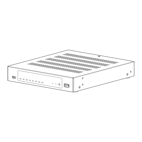
BeFORe uSING The CONTROLLeR Panel description ■ Front panel 2 3 4 5 6 7 9 10 11 INDICATORS [POWER] �������� Lights green: Power is ON Blinks green: Booting up Lights orange: Boot loader is booting Lights red: Boot loader prompt stopped Blinks red: uID indication L Used for identification purpose by administrator (operation on the web) in such case as 2 or more IP1100CVs are installed in a system. - Page 7 Controller from a PC using a terminal software (user supplied.) About the USB driver To use the [CONSOLe] port, the uSB driver for the Icom network devices is required. Download the uSB driver from the Icom website and install it on your https://www.icomjapan.com/support/...
-
Page 8: Rear Panel
BeFORe uSING The CONTROLLeR Panel description ■ Rear panel [GND] TERMINAL ���� Connect to ground. [DC] JACK ������� Connect the supplied power adapter. [LAN] PORT (RJ-45 type) ������� Connect a network device such as a Switch. Lights: Connected Blinks: Communicating q Green: 1000BASE-T/2.5GBASE-T w Orange: 100BASE-TX [WAN] PORT... -
Page 9: Side Panel
BeFORe uSING The CONTROLLeR Panel description ■ Side panel Security slot ������ Attach a security wire (user supplied). Refer to the instruction manual that comes with the security wire for details. -
Page 10: Feature Description
BeFORe uSING The CONTROLLeR Feature description ■ Controlling wireless LAN transceivers You can communicate through IP networks using the IP1100CV as a controller for up to 300 WLAN transceivers. L A wireless access point is required. L The IP100h, IP110h, and IP100FS are usable, as of June, 2023. -
Page 11: Simplex And Full-Duplex Communication
L To use the VOX function, an optional headset (and connection cable, depending on the headset) are required. See the WLAN transceiver’s manual for details. ■ Multiple communication WLAN transceivers can simultaneously make multiple communications in an IP1100CV system since crosstalk does not occur in an IP network. IP1100CV... -
Page 12: All Calls And Group Calls
(Destination Settings > Destination Settings) L The ID List and the destination settings set in the IP1100CV are commonly used in each group that the WLAN transceivers and IP100FS belong to. You can select Simplex or Full-Duplex communication for All Calls and Group Calls. -
Page 13: Talkgroup Calls
■ Talkgroup Calls Talkgroup Calls enables WLAN transceivers to select the group that belong to it from previously registered groups in the IP1100CV. When users select Talkgroup 01000, terminals are excluded from the original groups, as illustrated below. When no Talkgroup is selected:... -
Page 14: Individual Call
L If the destination that you are calling is out of range, “No response” is displayed. L Set the Receive Notification Tone on the [Profile] screen to notify a connection status, if necessary. (Transceiver Controller > Common Settings > Profile) IP1100CV Selecting an Individual Call Individual call... -
Page 15: Priority Call And Its Priority
(Transceiver Controller > RoIP Server Settings > RoIP Server) • The call priority between the same priority level depends on the incoming order. • The priority of the reply call depends on the caller’s priority level. Priority call interruption example: IP1100CV Wireless access point Group call... -
Page 16: Area Calls
(Transceiver Controller > Transceiver Settings > Transceiver Settings > Function Settings > Area Call) (Transceiver Controller > RoIP Server Settings > Area Call > Area Setting) Making an All Call with the Area Call function IP1100CV Wireless access point Sales... -
Page 17: Messages
The Messages function enables you to communicate with preset messages of up to 32 characters between WLAN transceivers and IP100FS. (Default: Disable) You can register up to 10 messages to the IP1100CV on the [Messages] screen. (Transceiver Controller > Common Settings > Messages) Example: Sending a message with All Call... -
Page 18: Status Settings
Displays Name, Destination ID, Status number, and the Status information IP110h Status selection screen (Sender) On the IP1100CV On the Controller, you can check the Status of each WLAN transceiver on the [Transceiver Management] screen. (Transceiver Controller > Transceiver Management) 1-14... -
Page 19: The Router Function
BeFORe uSING The CONTROLLeR Feature description ■ The Router function When the router function of the IP1100CV is enabled, the devices such as PCs that are connected to the IP1100CV can access the Internet. (Default: Disable) L To use the router function, set the [Connection Type] (DhCP Client, Static IP, or PPPoe) and detailed settings according to your Internet environment. -
Page 20: Installation And Connections
BeFORe uSING The CONTROLLeR Installation and connections ■ Attaching the magnetic legs You can the supplied 4 magnetic legs on the bottom panel, and tighten the supplied screws to fix them. L Never use other than the supplied screws. Screw (supplied) Magnetic leg (supplied) 1-16... -
Page 21: Setting A Static Ip Address To A Pc
To access the IP1100CV setting screen from a PC, set a static IP address to the PC. L As the default for the IP1100CV, the IP address is set to “192.168.0.1,” and the DhCP server is set to “Disable.” The following steps shows how to set a static IP address (example: 192.168.0.100), based on Microsoft Windows 10. -
Page 22: Connecting The Cables And The Pc
L use a LAN cable of category 5e or higher Lights: Connected Blinks: Communicating q Green: 1000BASE-T/2.5GBASE-T w Orange: 100BASE-TX Connect to the power supply To an AC outlet To a IP1100CV ground BC-207S or BC-236 (IP address example : 192.168.0.1) AC adapter terminal ( Purchase Separately) Connect cables... -
Page 23: The Setting Screen
IP address of the IP1100CV into the address bar. (Default: 192.168.0.1) enter Press the [enter] key. • When you access the IP1100CV for the first time, you have to set an Administrator password on the Initial Login screen. Go to Step 3. Otherwise, go to Step 4. -
Page 24: Setting Screen Description
BeFORe uSING The CONTROLLeR The Setting screen ■ Setting screen description Refer to the Operating guide for each setting item details. Menu list �������� Displays the list on a menu line. When you click each menu, a list of the submenu drops down so you can click to display the setting screen to the right. -
Page 25: Changing The Ip Address On The Setting Screen
IP Address assigning An IP Address consists of two parts, the “Network” and “host.” For example, in the IP1100CV IP address “192.168.0.1” (Class C), the digits “192.168.0” are the network digits and the “1” at the end is the host digit. - Page 26 SETTING UP THE SYSTEM Section Installation overview…………………………………………………………………………………………………… 2-2 Configuring the WLAN transceiver system ………………………………………………………………………… 2-4 ■ Connecting to WLAN transceivers …………………………………………………………………………… 2-4 ■ Registering the WLAN transceivers …………………………………………………………………………… 2-5 ■ Checking the WLAN transceiver settings …………………………………………………………………… 2-6 ■ The Transceiver Settings ……………………………………………………………………………………… 2-7 ■...
-
Page 27: Installation Overview
SETTING uP ThE SySTEM Installation overview The following shows a typical setting procedure for the WLAN transceiver controller on the IP1100CV Setting screen. Network Settings > IP Address Enter the IP address according to your network environment. (Default: 192.168.0.1) Network Settings > DHCP Server Enable or disable the Controller’s DhCP server function. - Page 28 SETTING uP ThE SySTEM Installation overview Transceiver Controller > Common Settings Set the common settings of each group that the WLAN transceivers or IP100FSs belong to, and are registered on the Transceiver Registration screen. ID List screen Register the unit IDs that are registered on the Transceiver Registration screen, or the group IDs that are registered on the Destination Settings screen.
-
Page 29: Configuring The Wlan Transceiver System
DhCP server in the same network as the Controller. • When assigning static IP addresses to the terminals, make sure that the addresses of the devices on the network don’t overlap or conflict. Wireless access point Example: AP-95M IP1100CV 192.168.0.50 192.168.0.1 IP110H IP100H... -
Page 30: Registering The Wlan Transceivers
SETTING uP ThE SySTEM Configuring the WLAN transceiver system ■ Registering the WLAN transceivers Register a WLAN transceiver or the IP100FS to the Controller. Open the Transceiver Registration screen. (Transceiver Controller > Transceiver Settings > Transceiver Registration) In [Transceiver Settings], enter the Transceiver Model, Name, and unit ID (00001 ~ 60000), and then click <Add>. -
Page 31: Checking The Wlan Transceiver Settings
SETTING uP ThE SySTEM Configuring the WLAN transceiver system ■ Checking the WLAN transceiver settings After registering the WLAN transceiver (Example: IP110h) to the Controller, enter the required settings of the IP110h on the PC, using the CS-IP110h programming software After the settings on the programming software have been applied to the WLAN transceiver, restart the WLAN transceiver to connect to the Controller to receive the settings from it. -
Page 32: The Transceiver Settings
SETTING uP ThE SySTEM Configuring the WLAN transceiver system Transceiver Controller > Transceiver Settings > Transceiver Settings ■ The Transceiver Settings Set up each registered transceiver. L After completing the settings on this screen, restart the transceiver to apply them. Open the Transceiver Settings screen. -
Page 33: The Group Call
SETTING uP ThE SySTEM Configuring the WLAN transceiver system Destination Settings > Destination Settings ■ The Group Call When registering WLAN transceivers or IP100FSs to a group, you can communicate in Full-Duplex, between three or more members in a conference call mode. L you have to enter a Group and the Phonebook on the setting screen to make a Group Call. -
Page 34: The Talkgroup Call
SETTING uP ThE SySTEM Configuring the WLAN transceiver system Destination Settings > Destination Settings ■ The Talkgroup Call you can join a Talkgroup by selecting it from the preset Talkgroups on your WLAN transceiver. you can make a call to the selected Talkgroup. L you have to set about the Talkgroup Call and enter Talkgroup IDs to your phonebook. -
Page 35: The Id List
SETTING uP ThE SySTEM Configuring the WLAN transceiver system Transceiver Controller > Common Settings > ID List ■ The ID List Enter names, call types and so on into an ID list that the WLAN transceiver will use. L Set “use ID List” to “Enable” to use the ID list. (Transceiver Controller >... -
Page 36: The Messages
SETTING uP ThE SySTEM Configuring the WLAN transceiver system Transceiver Controller > Common Settings > Messages ■ The Messages Enter messages that the WLAN transceiver will transmit. L Set “Message” to “Enable” to use the Message. (Transceiver Controller > Transceiver Settings > Transceiver Settings > Transceiver Settings) L After completing the settings on this screen, restart the transceiver to apply them. -
Page 37: The Status
SETTING uP ThE SySTEM Configuring the WLAN transceiver system Transceiver Controller > Common Settings > Status ■ The Status Enter a status that the WLAN transceiver will transmit. L Set “Status” to “Enable” to use the status. (Transceiver Controller > Transceiver Settings > Transceiver Settings > Transceiver Settings) L After completing the settings on this screen, restart the transceiver to apply them. -
Page 38: Setting The Common Id List And Messages In The Group
SETTING uP ThE SySTEM Configuring the WLAN transceiver system Transceiver Controller > Common Settings > Profile ■ Setting the common ID List and Messages in the group you can set the ID list and messages that are commonly used by the WLAN transceivers in a particular group. L After completing the settings on this screen, restart the transceiver to apply them. -
Page 39: Additional Controller Link
L up to 10 sub IP1100CVs can be connected to the master IP1100CV. L The VPN function on the IP1100CV is compatible with the VE-PG4. (As of June, 2023) The IP100H and the IP110H make a Group Call with the Additional Controller Link IP1100CV 192.168.0.1... - Page 40 SETTING uP ThE SySTEM Additional controller link The IP100H and the IP110H make a Group Call with the Additional Controller Link IP1100CV 192.168.0.1 Wireless Office1 (Master) access point Additional Controller Link Sales1 Sales2 Sales group1 00001 00002 00101 192.168.0.2 192.168.0.3...
- Page 41 About the Office2 setting (Sub) Example: Calling Sales group2 (00201) Select “Sub” in [Controller Mode]. Then click <Apply> to reboot the IP1100CV. (Transceiver Controller > RoIP Settings) Enter a name and a destination IP address, then click <Apply>. (Example: Office1 (Master)).
- Page 42 SETTING uP ThE SySTEM Additional controller link The IP100H and the IP110H make a Group Call with the Additional Controller Link IP1100CV 192.168.0.1 Wireless Office1 (Master) access point Additional Controller Link Sales1 Sales2 Sales group1 00001 00002 00101 192.168.0.2 192.168.0.3...
- Page 43 00301 About the Office3 setting (Sub) Select “Sub” in [Controller Mode]. Then click <Apply> to reboot the IP1100CV. (Transceiver Controller > RoIP Settings) Enter a name and a destination IP address, then click <Apply>. (Example: Office1 (Master)) (Transceiver Controller > RoIP Server Settings > Additional Controller Link)
- Page 44 SETTING uP ThE SySTEM Additional controller link The IP100H and the IP110H make a Group Call with the Additional Controller Link IP1100CV 192.168.0.1 Wireless Office1 (Master) access point Additional Controller Link Sales1 Sales2 Sales group1 00001 00002 00101 192.168.0.2 192.168.0.3...
-
Page 45: Bridge Connection And Caller Settings
SETTING uP ThE SySTEM Bridge connection and Caller settings When making a bridge connection with the VE-PG3*, the IP1100CV system can communicate with the transceivers. * The VE-PG3 with a firmware version 1.13 or earlier cannot communicate with the IP1100CV system. - Page 46 00002 Seles group1 00001 00011 About the IP1100CV settings Confirm that “Clear Down during Telephone Call” in [Transceiver Settings] is set to “Enable.” (Transceiver Controller > Transceiver Settings > Transceiver Settings) When “Clear Down” is selected in [Option Key], “Clear Down during Telephone call” is not displayed.
- Page 47 00001 00011 About the VE-PG3 settings (Converter mode) Enter the IP address of the IP1100CV in [Bridge Connection]. (Example: 192.168.0.1) Select the Voice Cording. (Example: G.711u Signaling) (Port Settings > Bridge ( Example: Bridge1) ) L Make sure that the port number used for the connection does not duplicate with any other connection.
- Page 48 SETTING uP ThE SySTEM Bridge connection and Caller settings Bridge connection Extension number 2001 VE-PG3 (RoIP Gateway) IP1100CV 192.168.0.2 192.168.0.1 Wireless IP100H IP110H access points IP phone Extension number 500 Sales2 Sales1 00002 Seles group1 00001 00011 About the VE-PG3 settings (Converter mode) Enter the extension number of the [Bridge 1] port in [Extension Number].
-
Page 49: Additional Controller Link With Ve
(Transceiver Controller > RoIP Settings) L When several IP1100CVs are linked and use All call or Group call between the controllers, the IP1100CV whose Controller mode is set to “Sub” cannot link to the bridge mode’s VE-PG3 to additional controller. - Page 50 Port number (D-TRX1): 21502 Sales group3 00031 00032 00301 About the IP1100CV setting Select “Group” in [Call Type], enter a destination ID. Select controllers in [Additional Controller]. (Refer to an example below.) Click <Apply>. (Destination Settings > Destination Settings) 2-25...
- Page 51 SETTING uP ThE SySTEM Bridge connection and Caller settings ■ Additional controller link with VE-PG3 IP100H and IP110H make Group Call with the Additional Controller Link (VE-PG3) Additional Controller Link VE-PG3 IP1100CV (RoIP Gateway) Controller connection Repeater A [D-TRX1] [USB] 192.168.0.11...
- Page 52 SETTING uP ThE SySTEM Bridge connection and Caller settings ■ Additional controller link with VE-PG3 IP100H and IP110H make Group Call with the Additional Controller Link (VE-PG3) Additional Controller Link VE-PG3 IP1100CV (RoIP Gateway) Controller connection Repeater A [D-TRX1] [USB] 192.168.0.11...
- Page 53 SETTING uP ThE SySTEM Bridge connection and Caller settings ■ Additional controller link with VE-PG3 IP100H and IP110H make Group Call with the Additional Controller Link (VE-PG3) Additional Controller Link VE-PG3 IP1100CV (RoIP Gateway) Controller connection Repeater A [D-TRX1] [USB] 192.168.0.11...
- Page 54 SETTING uP ThE SySTEM Bridge connection and Caller settings ■ Additional controller link with VE-PG3 IP100H and IP110H make Group Call with the Additional Controller Link (VE-PG3) Additional Controller Link VE-PG3 IP1100CV (RoIP Gateway) Controller connection Repeater A [D-TRX1] [USB] 192.168.0.11...
- Page 55 About the VE-PG3 settings (Bridge mode) Enter the IP address of the IP1100CV in [Controller Connection]. (Example: 192.168.0.3) Enter the Controller Port Number same as the IP1100CV’s Service port number in Link setting. (Example: 32000) Enter the Local Port Number same as the IP1100CV’s Destination Port number in Additional Controller Settings.
- Page 56 MAINTENANCE Section Checking and saving the settings …………………………………………………………………………………… 3-2 Restoring the saved settings ………………………………………………………………………………………… 3-3 Resetting to the factory defaults …………………………………………………………………………………… 3-4 ■ Pushing the <INIT> button ……………………………………………………………………………………… 3-4 ■ Resetting on the setting screen ……………………………………………………………………………… 3-5 Updating the firmware ………………………………………………………………………………………………… 3-6 ■...
-
Page 57: Checking And Saving The Settings
You can check the settings changed on the setting screen, and then save them as a setting file (format: .sav) on your PC. L The saved file (.sav) is not usable on devices other than the IP1100CV. L You can use the saved file as a backup if the settings are lost or damaged. -
Page 58: Restoring The Saved Settings
MAINTENANCE Restoring the saved settings Management > Settings Backup/Restore You can restore a previously saved setting file in the previous page to the IP1100CV. NOTE: DO NOT write the saved file to any other devices. Open the Settings Backup/Restore screen. -
Page 59: Resetting To The Factory Defaults
Resetting to the factory defaults When you reconfigure your network, and so on, you can reset the IP1100CV to the factory defaults. There are two ways to reset to the factory defaults. Choose an appropriate way, according to your situation. -
Page 60: Resetting On The Setting Screen
Click • The Controller restarts to restore the settings. It may take several minutes to completely reboots. CAUTION: DO NOT turn OFF both the IP1100CV and the PC while the IP1100CV is restoring or rebooting. After the Controller has completely rebooted, click “[Back]” (the red text on the screen) to return to the setting screen. -
Page 61: Updating The Firmware
You can update the firmware of the IP1100CV in 4 ways. • Manual update: In the case that the Controller cannot do the automatic update, first download the latest firmware from the Icom website, and then manually load the saved firmware. (p. 3-7) • Online update: Automatically updates the firmware through the Internet. -
Page 62: Manual Update
Before updating the firmware, save the current setting into a file. NOTE: Some settings may be returned to their defaults after the firmware update. Refer to the Icom website for details. TIP: In order to protect the Controller from maintenance by unknown users, Icom recommends restricting access to the setting screen during normal use. -
Page 63: Online Update
2 Confirm Click <Update Firmware>. • The Controller starts accessing the Icom server to download the updates. L Depending on the firmware version, the Controller may require that you initialize the settings. Before the Online update, we recommend that you save your Controller settings for a backup. -
Page 64: Online Update With The
MAINTENANCE Updating the firmware Management > Firmware Update ■ Online update with the <UPDATE> button You can check whether a new firmware version is available or not by pushing the <UPDATE> button on the front panel of the Controller. The [MSG] indicator on the front panel of the Controller lights green if the firmware is ready for an online update.Button -
Page 65: Automatic Restoring From A Usb Flash Drive
• The source data is damaged. • The source data is not for the IP1100CV. • When both the firmware and settings for the IP1100CV are saved in the USB flash drive, the firmware will be updated after the settings data is loaded. -
Page 66: About The File Names
The files that are saved on a USB flash drive for the automatic restore function must be named as follows: • Settings file: savedata.sav L Only the settings file that is saved on the IP1100CV setting screen can be used for the Automatic Restore function. (Management > Settings Backup > Settings Backup) • Firmware: firmware.dat... -
Page 67: Managing 2 Or More Ip1100Cvs With A Usb Flash Drive
■ Managing 2 or more IP1100CVs with a USB flash drive You can backup or restore the setting files for 2 or more IP1100CVs by making a separate folder for each IP1100CV. Before inserting the USB flash drive into the IP1100CV, make folders that are named the same as the MAC address for the LAN of the IP1100CVs that you want to manage with the drive. -
Page 68: Restoring The Settings From The Usb Flash Drive
MAINTENANCE Restoring the settings from the USB flash drive Management > Settings Backup/Restore You can copy a Controller settings to use to clone another gateway, with a USB flash drive. First, save the settings data of that you want to copy from onto the USB flash drive, then load the settings to another Controller. - Page 69 Management > Settings Backup/Restore Unmount and remove the USB flash drive from the PC. Locate the IP1100CV that you want to load settings from the USB flash drive. Insert the USB flash drive to the Controller. • The [USB] indicator lights green when the USB flash drive is successfully mounted.
-
Page 70: Updating The Firmware From A Usb Flash Drive
Save the firmware data onto the USB flash drive, with the file name “firmware.dat.” L If there is a specific folder of the IP1100CV, save the firmware into the folder. L The IP1100CV cannot read the firmware from the other file than “firmware.dat.“... -
Page 71: Issuing A Usb Authentication Key
MAINTENANCE Issuing a USB authentication key Management > Management Tools By setting an authentication key and saving it to a USB flash drive, you can securely authenticate the USB flash drive that is used for automatic backup and restore, or updating the firmware. When the USB authentication key is set, the Controller reads or writes the setting data or the firmware from/to only the USB flash drive that has a matching authentication key. - Page 72 MAINTENANCE Issuing a USB authentication key When the following dialog is displayed, click <Next>. Click When an authentication key already exists, you are asked if you want to overwrite it or not. Click <Close>. Click Confirm the [POWER] indicator lights green, and hold down the <USB EJECT>...
- Page 73 FOR YOUR INFORMATION Section Troubleshooting ……………………………………………………………………………………………………… 4-2 Accessing with Telnet/SSH …………………………………………………………………………………………… 4-4 ■ Accessing the Controller with Telnet/SSH …………………………………………………………………… 4-4 ■ About Telnet/SSH commands ………………………………………………………………………………… 4-4 ■ Using the [CONSOLE] port …………………………………………………………………………………… 4-5 The setting screen menu list ………………………………………………………………………………………… 4-6 The feature functions …………………………………………………………………………………………………...
-
Page 74: Troubleshooting
Cannot access the Controller through the [WAN] port while the Router function is in use • The default IP filter setting blocks the packets from the [WAN] port. - Change the IP filter setting. L icom is not responsible for any accidents caused by the security degradation. - Page 75 FOr yOUr iNFOrmATiON Troubleshooting The inserted USB flash drive is not recognized • The USB function is set to “Disable.” - Enable the USB Flash Drive setting on the Setting screen. (management > management Tools > USB > USB Flash Drive) [Input/Output Digital Gain] doesn’t work •...
-
Page 76: Accessing With Telnet/Ssh
Password: Enter the administrator password set on the Administrator screen. (management > Administrator > Administrator Password) 2. When Telnet/SSH is successfully connected to the Controller, “iP1100CV>” is displayed. Saving the setting: After making changes, enter “save,” and then push the [Enter] key. -
Page 77: Using The [Console] Port
USB port of the PC through a USB (Type-C) cable (user supplied). The USB driver for the icom network devices is required. Download the USB driver and the manual from the icom web site and install it according to the manual. https://www.icomjapan.com/support/ After installing the USB driver, set the serial port settings in the terminal software as follows: •... -
Page 78: The Setting Screen Menu List
FOr yOUr iNFOrmATiON The setting screen menu list The list of the menu items, displayed on the iP1100CV setting screen by default. menu Setting screen Setting item System Status mAC Address information Network Status interface List Ethernet Port Connection Status... - Page 79 FOr yOUr iNFOrmATiON The setting screen menu list menu Setting screen Setting item Transceiver Controller Transceiver registration Transceiver Settings Transceiver Setting Entry List TrX Batch Setting Transceiver Settings Transceiver Settings Certificate Management Copy Transceiver Settings Transceiver Setting List Wireless LAN Wireless LAN List of Wireless LAN Entries iD List...
- Page 80 FOr yOUr iNFOrmATiON The setting screen menu list menu Setting screen Setting item management Factory Defaults Factory Defaults Firmware Update Firmware Status Online Update Automatic Update manual Update Transceiver Firmware Update Transceiver Firmware Status Online Update...
-
Page 81: The Feature Functions
• Browser maintenance (HTTP/HTTPS) • Additional controller link • Telnet maintenance (TELNET/SSH) • Bridge connection to the VE-PG3 • Console maintenance (USB) • Communication with the icom transceivers • Online Firmware updates (manual/Automatic) (requires VE-PG3) Router • PPPoE connection • iP masquerade •... -
Page 82: Specifications
FOr yOUr iNFOrmATiON Specifications ■ General All stated specifications are subject to change without notice or obligation. Power supply: 12 V DC ±10% [Polarity: The optional power adapter (BC-207S, 100–240 V AC ±10%) maximum 33 W (with the BC-207S) Usable condition: Temperature 0 to 40°C, +32 to +104°F, Humidity 5–95% (At no condensation) Dimension (approximate): 213 (W) ×... - Page 83 How the World Communicates A7698-2EX-1a 1-1-32 Kamiminami, Hirano-ku, Osaka 547-0003, Japan © 2022–2023 Icom Inc. Jun. 2023...
Need help?
Do you have a question about the IP1100CV and is the answer not in the manual?
Questions and answers