Sign In
Upload
Download
Table of Contents
Contents
Add to my manuals
Delete from my manuals
Share
URL of this page:
HTML Link:
Bookmark this page
Add
Manual will be automatically added to "My Manuals"
Print this page
×
Bookmark added
×
Added to my manuals
Manuals
Brands
Icom Manuals
Controller
IC-900
Manual
Icom IC-900 Manual
Band module controller
Hide thumbs
1
2
3
Table Of Contents
4
5
6
7
8
9
10
11
12
13
14
15
16
17
18
19
20
21
22
23
24
25
page
of
25
Go
/
25
Contents
Table of Contents
Bookmarks
Table of Contents
Table of Contents
Getting Started
Default Settings
Building a Cable to Interface the RLC-1 to the RLC-ICM Interface
Building a Cable to Interface the RLC-2 to the RLC-ICM Interface
Building a Cable to Interface the RLC-3 to the RLC-ICM Interface
Power Connection
Radio Interface Modules
Setup RLC-ICOM Interface with the RLC-1 Controller
Programming the RLC-ICM with the RLC-1 Controller
Setup RLC-ICOM Interface with the RLC-2 Controller
Programming the RLC-ICM with the RLC-2
PL Frequency Using the TS-64 PL Module
RLC-2 Examples
Setup and Programming the RLC-ICM with the RLC-3
Special Considerations
Installing the TS-64 Tone Module
Schematic Drawings
Board Layouts
Advertisement
Quick Links
Download this manual
RLC-ICM
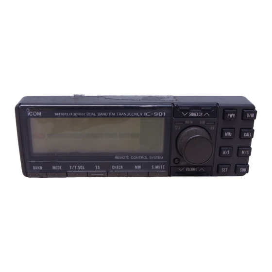
Icom IC-900/901 Band Module Controller
Link Communications Inc.
P.O. Box 1071
Sidney, MT 59270
Table of
Contents
Previous
Page
Next
Page
1
2
3
4
5
Advertisement
Table of Contents
Need help?
Do you have a question about the IC-900 and is the answer not in the manual?
Ask a question
Questions and answers
Related Manuals for Icom IC-900
Controller Icom IP1000C Instruction Manual
Ip advanced radio system controller (149 pages)
Controller Icom IP1000C User Manual
Ip advanced radio system controller (2 pages)
Controller Icom IP1000C Quick Start Manual
Ip advanced radio system controller (2 pages)
Controller Icom IP1000C Instruction Manual
Ip advanced radio system controller (246 pages)
Controller ICOM UC-FR5000 Instructions
Trunking/network controller (2 pages)
Controller Icom IC-FC5000E Service Manual
Idas trunking controller (23 pages)
Controller Icom DSC CONTROLLER DS-100 Instruction Manual
Dsc controller (36 pages)
Controller Icom IC-FC5000E Instructions
Idas trunking controller (2 pages)
Controller Icom IP1100CV Installation Manual
Wlan transceiver controller (83 pages)
This manual is also suitable for:
Ic-901
Table of Contents
Print
Rename the bookmark
Delete bookmark?
Delete from my manuals?
Login
Sign In
OR
Sign in with Facebook
Sign in with Google
Upload manual
Upload from disk
Upload from URL


Need help?
Do you have a question about the IC-900 and is the answer not in the manual?
Questions and answers