
Subscribe to Our Youtube Channel
Related Manuals for Emerson Machinery Health AMS EZ 1000


Summary of Contents for Emerson Machinery Health AMS EZ 1000
- Page 1 Operating Manual MHM-97884, Rev 1.8 October 2023 ™ Machinery Health Sensor AMS EZ 1000 Converter for Eddy Current Sensors...
- Page 2 Information in this document is subject to change without notice and does not represent a commitment on the part of Emerson. The information in this manual is not all-inclusive and cannot cover all unique situations.
- Page 3 Opmerking m.b.t. installatie van elektrische meet circuits in explosiegevaarlijke omgeving Dient de installatie van elektrische meet circuits in een explosiegevaarlijke omgeving te geschieden, moet men toezien dat de in de gebruikshandleiding opgenomen installatieinstructies worden nageleefd. Bij taalkundige problemen gelieve contact op te nemen met de fabrikant, deze zal u vervolgens een vertaling in de taal van het gebruiksland doen toekomen.
- Page 4 Piezīme par mērīšanas ķēžu instalēšanu sprādziena bīstamās zonās. Ja mērīšanas ķēde jāuzstāda sprādzienbīstamā zonâ, ir jāievēro lietošanas instrukcijā dotie instalēšanas norādījumi. Ja rodas kādas valodas grūtības, lūdzu griezieties pie izgatavotāja firmas, kas Jums nosūtīs nozīmīgâko nodaļu tulkojumus lietotāja valsts valodā. Emerson epro GmbH Jöbkesweg 3 48599 Gronau...
-
Page 5: Table Of Contents
Operating Manual Contents MHM-97884 October 2023 Contents Chapter 1 General.......................... 8 1.1 Using this manual..........................8 1.2 Symbols............................8 1.3 Liability and guarantee........................9 1.4 Incoming goods inspection......................9 1.5 Technical support........................... 10 1.6 Storage and transport........................10 1.7 Disposal of the device........................10 1.8 China RoHS Compliance......................... - Page 6 Contents Operating Manual October 2023 MHM-97884 6.4 Installation of the sensors....................... 45 6.5 CSA – Special conditions of safe use....................46 6.6 Technical data, explosion protection....................46 6.7 Control drawings..........................51 6.8 Revision history..........................54 Chapter 7 Hazardous location installation – application notes............55 7.1 Mark the converter as "once used without safety barrier"..............
- Page 7 Operating Manual Contents MHM-97884 October 2023 Chapter 11 Technical data......................108 11.1 Input............................108 11.2 Supply............................108 11.3 Output............................108 11.4 Errors and tolerances........................109 11.4.1 EZ1900-ADAP-90 adapter....................... 109 11.4.2 AMS EZ 1000 Converter with EZ105x..................109 11.4.3 AMS EZ 1000 Converter with EZ108x..................111 11.4.4 AMS EZ 1000 Converter with EZ116x..................113 11.4.5 AMS EZ 1000 Converter with PR 6424..................
-
Page 8: Chapter 1 General
General Operating Manual October 2023 MHM-97884 General Using this manual This manual contains information concerning the use of the device. Read the operating manual completely prior to starting installation and operating the device. Comply with all safety instructions. This operating manual applies for AMS EZ 1000 Converters with serial numbers 0000690 to 0001029 and P181900XXX and the safety-related variant of the converter labeled with EZ1000-SIS, revision ≥... -
Page 9: Liability And Guarantee
Liability and guarantee Emerson is not liable for damages that occur due to improper use. Proper use also includes the knowledge of, and compliance with, this document. Customer changes to the device that have not been expressly approved by Emerson will result in the loss of guarantee. -
Page 10: Technical Support
Product Service Center. Before shipping this product, contact Emerson Product Support to obtain a Return Materials Authorization (RMA) number and receive additional instructions. Product Support Emerson provides a variety of ways to reach your Product Support team to get the answers you need when you need them: Phone Toll free 800.833.8314 (U.S. -
Page 11: China Rohs Compliance
Operating Manual General MHM-97884 October 2023 Note Environmental hazards! Electrical waste and electronic components are subject to treatment as special waste and may only be disposed by approved specialized companies. China RoHS Compliance Our products manufactured later than June 30, 2016 and those which are sold in the People's Republic of China are marked with one of the following two logos to indicate the Environmental Friendly Use Period in which it can be used safely under normal operating conditions. - Page 12 General Operating Manual October 2023 MHM-97884 • Define a suitable measuring range, not larger than necessary, in consultation with the operator of the plant. • Define the trip limit in consultation with the operator of the plant. • Take measurement deviations into account when defining the trip limit. •...
-
Page 13: Chapter 2 Safety Instructions
Operating Manual Safety instructions MHM-97884 October 2023 Safety instructions To ensure safe operation, carefully observe all instructions in this manual. The correct and safe use of this device requires that operating and service personnel both understand and comply with general safety guidelines and observe the special safety comments listed in this manual. -
Page 14: Radio Interference
Safety instructions Operating Manual October 2023 MHM-97884 Radio interference The device is carefully shielded and tested to be technically immune to radio interference and complies with current standards. However, if you operate this device together with other peripheral devices that are not properly shielded against radio interference, disturbances and radio interferences may occur. -
Page 15: Application And Design
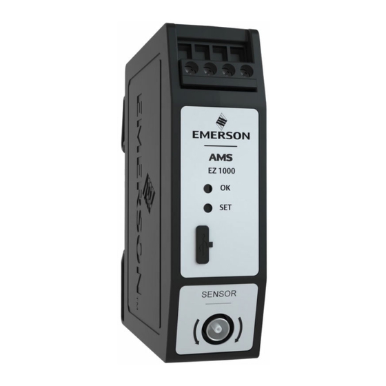
Operating Manual Application and design MHM-97884 October 2023 Application and design Application The AMS EZ 1000 Converter is a signal converter for different types of eddy current sensors. The converter is designed for the connection of eddy current sensors of the AMS EZ 1000 Sensor series, the listed types of the PR 642x series, and a selection of third party sensors: •... - Page 16 Application and design Operating Manual October 2023 MHM-97884 Figure 3-1: AMS EZ 1000 Converter A. Two screw terminals for -24 V DC supply voltage. B. Two screw terminals for sensor output signal (range: -2 V to -18 V) C. Green Channel OK LED (see Table 3-1) D.
- Page 17 Operating Manual Application and design MHM-97884 October 2023 Table 3-1: LED blinking pattern (continued) Event Blinking pattern Sequence Automatic calibration Unlimited fast flashing (5 Hz) – until power with AMS Machine off/on the converter Studio – failure detected Firmware update Slow flashing (1 Hz) while waiting for button press Steady light while erasing and writing the...
-
Page 18: Chapter 4 Function Principle
Function principle Operating Manual October 2023 MHM-97884 Function principle The measuring coil of the eddy current sensor (for example EZ105x-xx-xx-xxx or EZ108x- xx-xx-xxx) is connected to an oscillator circuit in the converter through a shielded connection cable. The oscillator circuit generates a high-frequency signal resulting in a high-frequency magnetic field around the tip of the eddy current probe. -
Page 19: Sensor Supervision
Operating Manual Function principle MHM-97884 October 2023 Note If installing a calibrated measuring chain at a different measuring point, ensure that the target material of this point is the same as of the previous point. Otherwise, recalibrate the converter on the new target material. Sensor supervision The AMS EZ 1000 Converter checks the connected sensor by supervising the signal voltage. - Page 20 Function principle Operating Manual October 2023 MHM-97884 Table 4-1: Causes for sensor not OK indication (continued) Cause Possible reasons Solution Sensor cable break Open connector. Check the sensor cable and connections. Replace Damaged sensor cable. a defective sensor. Check cable path to avoid further damages.
-
Page 21: Installation And Commissioning
Operating Manual Installation and commissioning MHM-97884 October 2023 Installation and commissioning CSA - General safety Equipment to be installed within another enclosure which provides the safety aspects and protects the operator from hazards and is suitable for outdoor environment conditions. Mounting Mount the AMS EZ 1000 Converter into a suitable housing that contains a mounting rail of type NS 35/7.5. -
Page 22: Installing An Ams Ez 1000 Converter Using The Optional Din Rail For Horizontal Mount Adapter
Installation and commissioning Operating Manual October 2023 MHM-97884 Snap the AMS EZ 1000 Converter onto the DIN rail as shown in Figure 5-2. Figure 5-2: DIN rail mounting A. AMS EZ 1000 Converter B. DIN rail type NS 35/7.5 C. Minimum required space on DIN rail: 26 mm 5.2.1 Installing an AMS EZ 1000 Converter using the optional DIN Rail for Horizontal Mount adapter... - Page 23 Operating Manual Installation and commissioning MHM-97884 October 2023 Figure 5-3: Parts DIN Rail for Horizontal Mount adapter A. Mounting rail adapter B. Base plate C. Mounting rail D. End clamp E. 2x washer for M4 screws F. 4x Hexagon socket head cap screw M4x5 Prerequisites 1.
- Page 24 Installation and commissioning Operating Manual October 2023 MHM-97884 mounting rail adapter in accordance to the desired alignment of the AMS EZ 1000 Converter. Figure 5-4: Possible base plate alignments Turn the mounting rail adapter with the positioned base plate upside down. The mounting rail adapter has four holes –...
- Page 25 Operating Manual Installation and commissioning MHM-97884 October 2023 Figure 5-6: Mounting rail adapter with base plate – top view A. Mounting rail adapter B. Base plate 2. Mount the mounting rail on the base plate by using two M4x5 screws and two washers as shown in Figure 5-7.
- Page 26 Installation and commissioning Operating Manual October 2023 MHM-97884 Figure 5-8: Adapter with AMS EZ 1000 Converter A. Adapter with two AMS EZ 1000 Converters – side view B. Adapter with one AMS EZ 1000 Converter – side view C. Adapter with AMS EZ 1000 Converter – front view 4.
-
Page 27: Hints For Installation And Connection
Hints for installation and connection To ensure the electromagnetic compatibility of the eddy current measuring chain, Emerson recommends using a double shielded twisted pair cable for connecting the AMS EZ 1000 Converter to the measuring amplifier, for example to an A6500-UM Universal Measurement Card of the AMS 6500 ATG system. -
Page 28: Connections And Wiring
Installation and commissioning Operating Manual October 2023 MHM-97884 Figure 5-11: Cable influence on the converter output signal Cable capacity 120 nF/km (wire/wire); signal frequency: A. 100 Hz B. 200 Hz C. 500 Hz D. 1000 Hz E. 2000 Hz F. 5000 Hz G. - Page 29 Operating Manual Installation and commissioning MHM-97884 October 2023 Table 5-1: Permissible wire cross-section Wire description Wire cross-section Minimum Maximum Conductor cross section solid 0.34 mm² 2.5 mm² Conductor cross section flexible 0.2 mm² 2.5 mm² Conductor cross section flexible, with ferrule without 0.25 mm²...
- Page 30 Installation and commissioning Operating Manual October 2023 MHM-97884 Figure 5-12: Connection example A. Cabinet B. Rear view of a slot of an AMS 6500 ATG backplane (x = slot number). C. Double shielded and twisted pair cable, for example LiYCY-CY 2x2x0.25mm² D.
- Page 31 Operating Manual Installation and commissioning MHM-97884 October 2023 3-wire connection Because of the higher immunity to external influences on the sensor signal the recommended connection type is the 4-wire connection as described in Power supply and output signal connection. If it is not possible to use the 4-wire connection, the AMS EZ 1000 Converter can also be connected by using three wires because of the internal interconnection of the GND terminals for power supply and output signal.
- Page 32 Installation and commissioning Operating Manual October 2023 MHM-97884 Figure 5-13: 3-wire connection example A. Cabinet B. Device with three connection terminals C. Signal input (GND) E. -24 V DC power supply F. Shielded connection cable G. Protection earth H. Screw terminal for power supply: -24 V I.
- Page 33 Operating Manual Installation and commissioning MHM-97884 October 2023 Sensor connection The following sensor types can be connected. • EZ105x-xx-xx-xxx, EZ108x-xx-xx-xxx, and EZ116x-xx-xx-xxx • PR 6424/0xx-xx0, PR 6425/010-1x0, and PR 6426/0x0-xx0 The sensor adapter EZ1900-003-ADAP-1 is required for the connection of these sensors.
- Page 34 Installation and commissioning Operating Manual October 2023 MHM-97884 Figure 5-16: EZ1900-ADAP-90 Adapter for EZ108x-xx-xx-xxx A. Connection to the EZ108x-xx-xx-xxx sensor B. Connection to the AMS EZ 1000 Converter (self-locking plug) Connection with EZ1900-ADAP-90 for how to connect the adapter to the AMS EZ 1000 Converter.
- Page 35 Operating Manual Installation and commissioning MHM-97884 October 2023 Figure 5-17: EZ1900-ADAP-90 – Dimensions A. 9.0 mm B. 18.5 mm C. 9.5 mm D. 17.5 mm E. Connection to the AMS EZ 1000 Converter F. Connection to the EZ108x-xx-xx-xxx sensor Connect Procedure 1.
-
Page 36: Adjustment Of Measuring Chains At The Machine
Installation and commissioning Operating Manual October 2023 MHM-97884 Disconnect Procedure 1. Turn the cap nut of the sensor connector counter clockwise to unfasten the sensor. 2. Unplug the sensor. If the sensor is connected with the EZ1900-ADAP-90 adapter, pull the adapter out of the sensor socket. -
Page 37: Sensors Ez105X-Xx-Xx-Xxx, Ez108X-Xx-Xx-Xxx, Ez116X-Xx-Xx-Xxx, Pr 6424/0Xx-Xx0, And Pr 6425/010-1X0
For sensors with an extension cable, Emerson recommends removing the extension cable to avoid twisting the cable during mounting and turning the sensor. Reconnect the extension cable before measuring the output voltage for the fine adjustment. - Page 38 Installation and commissioning Operating Manual October 2023 MHM-97884 Figure 5-18: Characteristic curve - dynamic A. Nominal distance B. Voltage range: -2 V to -18 V C. Sensor tip D. Shaft vibration signal E. 0-to-Peak F. Peak-to-Peak G. Quasi static displacement MHM-97884, Rev.
-
Page 39: Sensor Pr 6426/0X0-Xx0
If the distance between the mounting flange and the measuring target is not correct, adjust it by shifting the mounting flange. To achieve a precise adjustment, Emerson recommends using a linear guided support such as a bracket with a dovetail guide. See installation guide of the used sensor for further installation details. -
Page 40: Mutual Influences Of Two Measuring Chains
Installation and commissioning Operating Manual October 2023 MHM-97884 Note The position of the machine shaft must be known when adjusting the sensor for static measurement. Procedure 1. Adjust the distance between the sensor and the measuring target by shifting the bracket until the converter output signal has reached the required point on the characteristic curve. - Page 41 Operating Manual Installation and commissioning MHM-97884 October 2023 Table 5-2: Minimum distances and additional linearity error Sensor type De-tuned Not de-tuned Distance Additional Distance Additional linearity error linearity error EZ105x >12 mm <0.5 % >19 mm <5% EZ108x >12 mm <0.5 % >35 mm <5%...
-
Page 42: Hazardous Location Installation
Hazardous location installation Operating Manual October 2023 MHM-97884 Hazardous location installation Version 1.7 General installation requirements The AMS EZ 1000 Converter and the safety-related variant of the converter labeled with EZ1000-SIS are designed for the type of protection Ex ia as an intrinsically safe equipment (according to IEC / EN 60079-11) and for the type of protection Ex ec as an increased safety equipment (according to IEC / EN IEC 60079-7). -
Page 43: Installation Requirements - Intrinsic Safe
Operating Manual Hazardous location installation MHM-97884 October 2023 • The tip of the sensor types EZ105x, EZ108x, EZ116x, EZ116H, EZ132x, and PR 642x must be installed in such a way that a mechanical hazard (impact) can be excluded. • The terminal screws have to be tightened with a torque of 0.5 to 0.6 Nm. •... -
Page 44: Installation Requirements - Increased Safety
Hazardous location installation Operating Manual October 2023 MHM-97884 Installation requirements – increased safety The sensors EZ105x, EZ108x, EZ116x, EZ116H, EZ132x, and PR 642x are connected to the AMS EZ 1000 Converter with intrinsically protection class in Zone 2/Division 2 by internal protection of the AMS EZ 1000 Converter. -
Page 45: Installation Of The Sensors
Operating Manual Hazardous location installation MHM-97884 October 2023 Figure 6-1: Minimum dimension of the field housing cross section • Ensure that the cable glands match the diameter of the used cables. — Diameter EZ105x, EZ108x, EZ116x, EZ116H, EZ132x, and PR 642x sensor cable: 2.65 to 2.90 mm —... -
Page 46: Csa - Special Conditions Of Safe Use
Hazardous location installation Operating Manual October 2023 MHM-97884 1. Shrink the black shrink sleeve on the interconnector. 2. Additionally, shrink the blue shrink sleeve on the interconnector already isolated with the black shrink sleeve. Both shrink sleeves have to be positioned and shrank over the housing of the connector. Third party sensors must comply to the Ex i requirements. - Page 47 Operating Manual Hazardous location installation MHM-97884 October 2023 Table 6-1: cCSAus (continued) Class I, Division 2 Identification Group A, B, C, D T6, T4, T2 (Class 1, Zone 2) Ex/ AEx ec [ic] IIC T6 T4 T2 Gc T6 -35°C ≤ Ta ≤ 50°C T4 -35°C ≤...
- Page 48 Hazardous location installation Operating Manual October 2023 MHM-97884 Table 6-2: ATEX/IECEx (continued) IEC 60079-0:2017, Edition 7.0, Equipment - general requirements IEC 60079-7:2017, Edition 5.1, Increased safety ec ATEX approval number BVS 18 ATEX E 011 X IECEx approval number IECEx BVS 18.0009X MHM-97884, Rev.
- Page 49 Operating Manual Hazardous location installation MHM-97884 October 2023 Table 6-3: General Electrical data Output and supply circuit With explosion protection class Intrinsically safe, only for connection to certified intrinsically safe circuits with the following maximum values. -24 V / ┴/ ┴ / Out terminals Open-circuit voltage = -28 V Sum of short- circuit...
- Page 50 Hazardous location installation Operating Manual October 2023 MHM-97884 Table 6-4: Capacities and inductances of sensors including connection cable and extension cable (continued) Sensor Capacity (C Inductance (L Sensor Sensor EZ1900-003-ADAP-2 Adapter +39 pF negligible cable for connection of BN 33010x sensors EZ1900-ADAP-90 Elbow negligible negligible...
-
Page 51: Control Drawings
Operating Manual Hazardous location installation MHM-97884 October 2023 Control drawings MHM-97884, Rev. 1.8... - Page 52 Hazardous location installation Operating Manual October 2023 MHM-97884 MHM-97884, Rev. 1.8...
- Page 53 Operating Manual Hazardous location installation MHM-97884 October 2023 MHM-97884, Rev. 1.8...
-
Page 54: Revision History
Hazardous location installation Operating Manual October 2023 MHM-97884 Revision history Version Date Remarks/Changes 26. January 2018 Initial version 3. April 2018 Control Drawing update 10. July 2018 Grammar corrections 1. August 2018 Control Drawing update and addition to chapter 6.2 7. -
Page 55: Hazardous Location Installation - Application Notes
Operating Manual Hazardous location installation – application notes MHM-97884 October 2023 Hazardous location installation – application notes This chapter contains additional information about the installation of the AMS EZ 1000 Converter within hazardous areas. Before installing the AMS EZ 1000 Converter within hazardous areas observe the information of Hazardous location installation. -
Page 56: Ams Ez 1000 Converter With Ams 6500
Hazardous location installation – application notes Operating Manual October 2023 MHM-97884 AMS EZ 1000 Converter with AMS 6500 Use an additional diode when connecting an AMS EZ 1000 Converter through safety barriers to cards for eddy current sensors of the AMS 6500 system. The nominal voltage of the safety barriers with U = -28 V is slightly lower than the nominal supply voltage of the AMS 6500 cards for eddy current measuring chains. -
Page 57: Ams Ez 1000 Converter With Ex Isolation Transducers And Zener Barriers
AMS EZ 1000 Converter to an Ex isolation transducer. For detailed installation and connection information see the documentation of the used Ex installation transducer. Emerson recommends to use an external power supply to supply Ex isolation transducers as the nominal current of Ex isolation transducers is typically higher than the current provided by measurement cards such as the A6500-UM Universal Measurement card of the AMS 6500 ATG system. - Page 58 Hazardous location installation – application notes Operating Manual October 2023 MHM-97884 Figure 7-3: General connection example A. Hazardous area B. Non-hazardous area C. AMS EZ 1000 Sensor or PR642x D. AMS EZ 1000 Converter E. Ex Isolation Transducer F. Measuring Card such as an A6500-UM Universal Measuring card G.
-
Page 59: Ams Ez 1000 Converter With Zener Barriers
Operating Manual Hazardous location installation – application notes MHM-97884 October 2023 Figure 7-4: Reduced static distance measurement A. Output voltage B. Nominal output voltage range: -2.0 V to -18 V C. Reduced output voltage range: -2.0 V to -16 V D. - Page 60 Hazardous location installation – application notes Operating Manual October 2023 MHM-97884 Note Consider this behavior when planning a static distance measurement. When planning a dynamic distance measurement, ensure that the distance between sensor and measuring object is adjusted so that a connected multimeter reads a DC voltage of approximately -10 V.
- Page 61 Operating Manual Hazardous location installation – application notes MHM-97884 October 2023 Figure 7-6: A6500-UM card – input configuration A. Sensor supply boost Parameter MHM-97884, Rev. 1.8...
-
Page 62: Chapter 8 Configuration
Configuration Operating Manual October 2023 MHM-97884 Configuration General configuration procedure The configuration can be performed offline without connection to the AMS EZ 1000 Converter or online with a connection to the converter. In any case, the configuration must be loaded to the converter to become active. Prerequisites •... -
Page 63: Online Configuration Overview
5. Open the saved configuration file (window File, menu item Open). Note If a custom sensor file provided by Emerson has been opened, parameters that do not need to be configured are grayed out. 6. Check the configuration – does the configuration meet the requirements of the measurement? 7. -
Page 64: Start Of An Offline Configuration
Configuration Operating Manual October 2023 MHM-97884 Figure 8-2: Connection – computer to USB interface A. USB socket at the computer with AMS Machine Studio installed. B. USB interface at the converter front. 3. Start AMS Machine Studio. The AMS EZ 1000 Converter is automatically detected by AMS Machine Studio. 4. - Page 65 Operating Manual Configuration MHM-97884 October 2023 Figure 8-3: Start new device configuration A. Item EZ 1000 converter B. Workspace The AMS EZ 1000 Converter is added to the list below Workspace. 2. Select an EZ 1000 from the Workspace list, and click Configure. Figure 8-4: Select an AMS EZ 1000 Converter for offline configuration A.
-
Page 66: Start Of An Online Configuration
Configuration Operating Manual October 2023 MHM-97884 Figure 8-5: New Configuration dialog 3. Select EZ 1000, and click Create Configuration to open the configuration editor. Configuration editor and parameters for parameter description and settings. Note The calibration requires an online connection to the AMS EZ 1000 Converter. Move the converter configuration from Workspace by drag and drop to an already connected converter below Network. -
Page 67: Configuration Of An Already Existing Converter
Operating Manual Configuration MHM-97884 October 2023 Figure 8-6: Select an AMS EZ 1000 Converter for online configuration A. Button Configure for opening the configuration editor. B. Selected AMS EZ 1000 Converter. If the selected converter is not configured, the New Configuration dialog opens (see Start of an offline configuration). -
Page 68: Ribbon Command Bar
Configuration Operating Manual October 2023 MHM-97884 Figure 8-7: Configuration A. Ribbon command bar B. Configuration dialog C. Converter name with type of used interface in brackets D. List of configuration pages 8.5.1 Ribbon command bar New configuration Click New configuration to start a new configuration with default parameters. Figure 8-8: Button New configuration Send &... - Page 69 Operating Manual Configuration MHM-97884 October 2023 Major changes are: • The parameters Sensor and Extension cable on the Input tab. • All parameters on the Measurement tab. Figure 8-9: Button Send & close Note Send & close is disabled after major changes, which require a calibration of the converter, or if the calibration state of the converter is not OK (see Calibration state).
- Page 70 Configuration Operating Manual October 2023 MHM-97884 CAUTION The preset configuration on the converter including the calibration data will be deleted and replaced by the default configuration. Compare Click Compare to show differences between the configuration on the converter and in the memory of the used Laptop or PC.
- Page 71 Operating Manual Configuration MHM-97884 October 2023 Figure 8-14: General settings Show History/Drafts Click Show History/Drafts to open the History. Figure 8-15: Button Show History/Drafts Figure 8-16: History The right part of Figure 8-16 shows the configuration history. The individual files are marked with date, time, and type: MHM-97884, Rev.
-
Page 72: Basic
Configuration Operating Manual October 2023 MHM-97884 • Draft Config A saved preliminary configuration file which has not yet been sent to the converter. • Running Config This configuration file is running on the connected converter. • Running Config (historic) An old configuration file which was running in the past. The editor area is grayed out. -
Page 73: Input
Operating Manual Configuration MHM-97884 October 2023 Figure 8-19: Basic Name Enter the converter name or a short description of the measurement. Machine Enter the machine designation. Area Enter a name or a short description of the area where the machine is located. -
Page 74: Measurement
Configuration Operating Manual October 2023 MHM-97884 Serial number Enter the serial number of the used sensor. See sensor or sensor cable for the serial number. Extension If an extension cable is used, click the button behind the display field cable to open the selection dialog for the extension cable. - Page 75 Operating Manual Configuration MHM-97884 October 2023 Target Click the button behind the display field to open the selection dialog for material the material of the measuring object. The measuring object is the machine part the sensor is facing, such as machine shaft, measuring collar, or trigger wheel.
-
Page 76: Calibration
Configuration Operating Manual October 2023 MHM-97884 Example sensitivity EZ108x-xx-xx-xxx with standard measuring range: 7.87 V/mm 8.5.5 Calibration Enter the calibration parameters or start the automatic calibration. A wizard guides you through the calibration process. The AMS EZ 1000 Converter provides several methods for the calibration. Table 8-1 lists the available calibration methods depending on sensor type, cable length, and detune... - Page 77 Operating Manual Configuration MHM-97884 October 2023 process, ensure that the dialogs Input and Measurement have been completed in accordance to the requirements of the measurement and the used sensor. CAUTION Connections to external devices may be interrupted when sending configurations. The output voltage of the AMS EZ 1000 Converter is set to >...
- Page 78 Configuration Operating Manual October 2023 MHM-97884 Use this method for third party sensors, for a configuration with activated detuning (Measurement → Detune frequency), or to recalibrate an already calibrated measuring chain. Depending on the selected sensor (Input → Sensor), a calibration method is recommended.
- Page 79 Operating Manual Configuration MHM-97884 October 2023 Figure 8-24: Manual calibration Sensor Enter the sensor gain. See Figure 8-25 where to find the data if using gain an EZ105x, an EZ108x, or an EZ116x sensor. The abbreviation for the sensor gain on the label is SG. Figure 8-25: Location sensor data A.
- Page 80 Configuration Operating Manual October 2023 MHM-97884 label is CG. When using the EZ1900-ADAP-90 adapter to connect an EZ108x-xx-xx-xxx sensor, add 0.001 to the cable gain stated on the label to compensate for the adapter influence on the calibration. Figure 8-26: Location extension cable data A.
- Page 81 Operating Manual Configuration MHM-97884 October 2023 Procedure 1. Click Next to send the already entered configuration data to the AMS EZ 1000 Converter. CAUTION Connections to external devices may be interrupted when sending configurations. The output voltage of the AMS EZ 1000 Converter is set to > -1.5 V during this process.
- Page 82 Configuration Operating Manual October 2023 MHM-97884 Multipoint calibration – guided process The process steps after the selection of the calibration method are described below. Prerequisites • Calibration gauge (for example CAL 064) with micrometer screw gauge and material sample that matches the material of the measuring object (machine shaft). •...
- Page 83 Operating Manual Configuration MHM-97884 October 2023 The sending progress is displayed. 2. Click Next. Step 1 Step 2 are skipped if an already configured converter is connected and the parameters of the dialogs Basic, Input, and Measurement are unchanged. 3. Enter the expected temperature at the sensor mounting location as exact as possible.
- Page 84 Configuration Operating Manual October 2023 MHM-97884 Figure 8-28: Multipoint calibration A. Buttons for measurement of converter output voltage. B. Calibration point for the end of the measuring range (greatest distance between sensor and measuring object). C. Calibration point for the center of the measuring range. D.
- Page 85 Calibration – PR 6424, PR 6425, and PR 6426 sensors To achieve the best possible accuracy Emerson recommends the use of both calibration methods Automatic calibration and Multipoint calibration. If a measurement with a lower accuracy is sufficient use the calibration method Automatic calibration without using the Multipoint calibration afterwards.
-
Page 86: Send And Reload A Configuration
Configuration Operating Manual October 2023 MHM-97884 Send and Reload a configuration 8.6.1 Send a configuration CAUTION Connections to external devices may be interrupted when sending configurations. The output voltage of the AMS EZ 1000 Converter is set to > -1.5 V during this process. The configuration is generally sent during the calibration process. - Page 87 Operating Manual Configuration MHM-97884 October 2023 The AMS EZ 1000 Converter can be calibrated on EZ108x sensors with 5 m or 10 m sensor cable without using AMS Machine Studio, provided that the material of the measuring object is 42CrMo4. Note The offline calibration requires an AMS EZ 1000 Converter with factory default settings (delivery state).
- Page 88 Configuration Operating Manual October 2023 MHM-97884 Figure 8-29: LED and button location A. Green LED (OK) B. Calibration button (SET) 6. To complete the calibration, release the button. The calibration process starts and the double flashing of the LED continues for five seconds. The calibration is finished when the LED stops double flashing, and the light is constantly green.
-
Page 89: Components Database - Add A New Target Material
For additional target material data, go to the Emerson download portal. If the required material data is not available on the portal, contact Product Support. If required, Product Support will ask you to send in a sample of the target material to determine the material data. - Page 90 Configuration Operating Manual October 2023 MHM-97884 Note Once entered into the database, the material data cannot be changed, only deleted. The new target material is added to the components database and available for the converter configuration. Related information Technical support MHM-97884, Rev.
-
Page 91: Chapter 9 Online View
Operating Manual Online View MHM-97884 October 2023 Online View After connecting AMS Machine Studio with an AMS EZ 1000 Converter, the Online View of the converter appears. Figure 9-1: Online View – overview A. Connected devices in the device tree B. -
Page 92: Overview
Online View Operating Manual October 2023 MHM-97884 Figure 9-2: Online View Overview Overview contains several graphic objects to provide an overview about the converter status. Channel OK This graphic object displays the converter state. Figure 9-3: Channel OK – expanded object •... - Page 93 Operating Manual Online View MHM-97884 October 2023 Table 9-1: Flags Channel OK Flag Meaning Action Channel OK No fault detected. Sensor or converter fault Check sensor and converter including detected. wiring and connections Sensor is too close to the Check the distance between sensor measuring target.
-
Page 94: Details
Online View Operating Manual October 2023 MHM-97884 Table 9-2: Calibration state flags Flag Meaning Action Calibration Calibration is OK. state No calibration. Calibrate the converter. The Easy calibration or Repeat the Easy or Automatic Automatic calibration is not calibration. If this is not successful, calibrate the converter with the Manual Manual calibration –... - Page 95 Operating Manual Online View MHM-97884 October 2023 Figure 9-7: Details Service This graphic object displays temperatures measured by the internal temperature sensor. Figure 9-8: Service Curr. temp. Current temperature of the converter. Min. temp. Minimum temperature of the converter. Max. temp. Maximum temperature of the converter.
- Page 96 Online View Operating Manual October 2023 MHM-97884 Target material Material of the measuring object entered in the configuration (see Measurement). Detuning Displays the selected detuning level (see Measurement). Extended range Configured factor for the measuring range extension (see factor Measurement). Measuring range The beginning of the configured measuring range depends on the min.
- Page 97 Operating Manual Online View MHM-97884 October 2023 Figure 9-12: Extension cable Type Configured extension cable type. Cable length Length of the configured extension cable. Serial Serial number of the extension cable entered in the configuration (see Input). Calibration data This graphic object displays configured and determined calibration data. Figure 9-13: Calibration data Configuration Indicates the configuration state.
-
Page 98: Live Data
Online View Operating Manual October 2023 MHM-97884 Gain Value which has been determined for the gain during the calibration process. Offset Value which has been determined for the offset during the calibration process. Sensor frequency Value which has been determined for the sensor frequency offset offset during the calibration process. - Page 99 Operating Manual Online View MHM-97884 October 2023 1. Click the icon to activate the function. The button is colored light blue if the function is activated. 2. Place the mouse cursor close to the area of interest. 3. Left-click and hold. 4.
-
Page 100: Online Commands
Online View Operating Manual October 2023 MHM-97884 Online commands After the AMS EZ 1000 Converter is configured and operating, you can issue converter specific commands to the converter from the Online View. Note Ensure that there is an online connection to the converter before using these commands. Figure 9-16: Converter specific command buttons A. -
Page 101: Maintenance, Fault Finding, And Repair
CAUTION Any work on the system may impair machine protection. For quick fault finding, Emerson recommends connecting an identical sensor to the converter temporarily. If the tip of the sensor is moved to a metallic target, the output voltage of the converter must change from approximately -18 V to -2 V. -
Page 102: Replace An Ams Ez 1000 Converter
Maintenance, fault finding, and repair Operating Manual October 2023 MHM-97884 Also, use AMS Machine Studio to get an overview of the converter state. See Online View for details. 10.3 Replace an AMS EZ 1000 Converter It is not possible to repair a defective AMS EZ 1000 Converter. In case of defects, the converters must be replaced. -
Page 103: Replace A Sensor
To ensure proper work of the replaced converter, check the linearity of the measuring chain. See Linearity check for details. Emerson recommends calibrating the measuring chain – no matter whether the sensor or the converter has been replaced. Now, the new AMS EZ 1000 Converter is ready for operation. -
Page 104: Linearity Check
October 2023 MHM-97884 10.5 Linearity check Emerson recommends checking the linearity of the AMS EZ 1000 Converter after sensor or converter replacement and after changes to the configuration of the converter. Prerequisites • Calibration gauge (for example CAL 064) with micrometer screw gauge and material sample that matches the material of the measuring object (machine shaft). -
Page 105: Firmware Update
The firmware of the AMS EZ 1000 Converter can be updated by using AMS Machine Studio. Note Emerson recommends saving the configuration of the AMS EZ 1000 Converter before starting the update process. See operating manual Machine Studio - General Functions (MHM-97879) for details. - Page 106 Maintenance, fault finding, and repair Operating Manual October 2023 MHM-97884 • PC or Laptop with the latest version of AMS Machine Studio installed. • USB cable with Type-A and micro-USB B plug • Latest firmware file • Suitable tool for pressing the calibration button, such as a 2 mm screw driver or a pen. Procedure 1.
- Page 107 Operating Manual Maintenance, fault finding, and repair MHM-97884 October 2023 Do not remove the USB cable during the update process. After the successful firmware update, the AMS EZ 1000 Converter restarts and the LED switches to a steady light – provided that a sensor is connected and within the OK range.
-
Page 108: Chapter 11 Technical Data
Technical data Operating Manual October 2023 MHM-97884 Technical data Only specifications with indicated tolerances or limit values are required. Data without tolerances or without error limits are informative data and not guaranteed. Technology is under constant development, and specifications are subject to change without notice. If not otherwise specified, all data refer to a nominal supply voltage of -24 V, an environmental temperature of +23°C, and an output load of 100 kΩ. -
Page 109: Errors And Tolerances
Operating Manual Technical data MHM-97884 October 2023 Table 11-1: Influence of the signal switch-on-time and the converter warm-up-time on the linearity Signal switch-on-time Converter warm-up-time Linearity error 60 seconds <0.1% <10 minutes <1.5% <60 minutes <0.5% >60 minutes <0.1% Valid for a restart after the AMS EZ 1000 measuring chain has been in operation for at least 60 minutes. - Page 110 Power and sensor connected to the AMS EZ 1000 Converter for at least 10 minutes before measurement and calibration. • Emerson reference target material is 42CrMo4 (AISI 4140), unless otherwise stated. Note For measurements that require a higher measuring accuracy, factory calibrated measuring chains are available.
-
Page 111: Ams Ez 1000 Converter With Ez108X
Operating Manual Technical data MHM-97884 October 2023 Table 11-4: Additional inaccuracies – DSL (continued) Parameter Additional Additional Remarks Measurement Measurement Inaccuracy (DSL), Inaccuracy (DSL), Test range Operating range Automatic calibration 1.75% 2.0% Multipoint calibration 0.25% 0.5% Extended measuring range: 2.0 mm (Extended range factor: 2.0) Manual calibration... - Page 112 Power and sensor connected to the AMS EZ 1000 Converter for at least 10 minutes before measurement and calibration. • Emerson reference target material is 42CrMo4 (AISI 4140), unless otherwise stated. Note For measurements that require a higher measuring accuracy, factory calibrated measuring chains are available.
-
Page 113: Ams Ez 1000 Converter With Ez116X
Operating Manual Technical data MHM-97884 October 2023 Table 11-6: Additional inaccuracies – DSL (continued) Parameter Additional Additional Remarks Measurement Measurement Inaccuracy (DSL), Inaccuracy (DSL), Test range Operating range -1% to +8% at -35°C to +180°C (operating range EZ108x) Other cable lengths 0.5% 0.75% Other target materials... - Page 114 Power and sensor connected to the AMS EZ 1000 Converter for at least 10 minutes before measurement and calibration. • Emerson reference target material is 42CrMo4 (AISI 4140), unless otherwise stated. Note For measurements that require a higher measuring accuracy, factory calibrated measuring chains are available.
-
Page 115: Ams Ez 1000 Converter With Pr 6424
Operating Manual Technical data MHM-97884 October 2023 Table 11-9: Sensor temperature inaccuracies (continued) Measuring range Temperature range Additional linearity error 8 mm 0°C to +45°C ±3.0% (Test range converter) (Extended range factor: 2.0) -35°C to +85°C ± 8.0% (Operating range converter) 0°C to +45°C ±2.0% (Test range sensor) - Page 116 Power and sensor connected to the AMS EZ 1000 Converter for at least 10 minutes before measurement and calibration. • Emerson reference target material is 42CrMo4 (AISI 4140), unless otherwise stated. Note For measurements that require a higher measuring accuracy, factory calibrated measuring chains are available.
-
Page 117: Ams Ez 1000 Converter With Pr 6425
No ambient temperature change of the AMS EZ 1000 Converter during 1 hour before the measurement. Power and sensor connected to the AMS EZ 1000 Converter for at least 10 minutes before measurement and calibration. • Emerson reference target material is 42CrMo4 (AISI 4140), unless otherwise stated. MHM-97884, Rev. 1.8... -
Page 118: Ams Ez 1000 Converter With Pr 6426
Technical data Operating Manual October 2023 MHM-97884 Note For measurements that require a higher measuring accuracy, factory calibrated measuring chains are available. Accuracy of measuring chains different from the standard measuring chain Add the measurement inaccuracies in Table 11-14 to the values in Table 11-13 to get the accuracy of measuring chains different from the standard measuring chain. - Page 119 Power and sensor connected to the AMS EZ 1000 Converter for at least 10 minutes before measurement and calibration. • Emerson reference target material is 42CrMo4 (AISI 4140), unless otherwise stated. Note For measurements that require a higher measuring accuracy, factory calibrated measuring chains are available.
-
Page 120: Environmental Conditions And Mechanical Design
Technical data Operating Manual October 2023 MHM-97884 Table 11-17: Additional inaccuracies – DSL (continued) Parameter Additional Measurement Inaccuracy (DSL), Test range Extended measuring range: 24.0 mm (Extended range factor: 3.0) Automatic calibration ± 16.0% Multipoint calibration ± 3.5% Requires previous Automatic calibration, see Calibration –... - Page 121 Operating Manual Technical data MHM-97884 October 2023 Humidity 5 to 95%, non-condensing Additional linearity error of ±0.2% for EZ 105x and EZ 108x with 5 meter sensor cable and standard measuring range at 10 to 100 % relative humidity (rh), condensing. Airborne contaminants resistance ISA-S71.04-1985 class G3 Deviation of linearity error <1%...
-
Page 122: Chapter 12 Certificates
Certificates Operating Manual October 2023 MHM-97884 Certificates MHM-97884, Rev. 1.8... - Page 123 Operating Manual Certificates MHM-97884 October 2023 MHM-97884, Rev. 1.8...
-
Page 124: Index
Index Operating Manual October 2023 MHM-97884 Index Numerics 3-wire connection Firmware Frequency Function principle Adjustment Housing Basic Influence Input Installation Cable Length Type Calibration 2-Point Automatic Linearity check Manual Calibration state CCC Certification Channel OK 19, Machine Studio 15, 62, Close editor Maximum torque Commissioning... - Page 125 Operating Manual Index MHM-97884 October 2023 Reload Replacement Report Reset to factory default Send & close Sensitivity Sensor Frequency offset Gain Offset Sensor supervision Sensor types Show History/Draft Shrinkage tube Space Target material 18, 75, Technical support Voltage output Wire cross-section Wizard MHM-97884, Rev.
- Page 126 The Emerson logo is a trademark and service mark of Emerson Electric Co. The AMS logo is a mark of one of the Emerson family of companies. All other marks are the property of their respective owners.
Need help?
Do you have a question about the Machinery Health AMS EZ 1000 and is the answer not in the manual?
Questions and answers