
Subscribe to Our Youtube Channel
Related Manuals for Emerson Machinery Health PR 9268 Series


Summary of Contents for Emerson Machinery Health PR 9268 Series
- Page 1 Installation Guide MHM-97479 , Rev 3.6 November 2022 ™ Machinery Health Sensor PR 9268/xxx-xxx, Absolute Vibration Transducers...
- Page 2 Information in this document is subject to change without notice and does not represent a commitment on the part of Emerson. The information in this manual is not all-inclusive and cannot cover all unique situations.
- Page 3 Opmerking m.b.t. installatie van elektrische meet circuits in explosiegevaarlijke omgeving Dient de installatie van elektrische meet circuits in een explosiegevaarlijke omgeving te geschieden, moet men toezien dat de in de gebruikshandleiding opgenomen installatieinstructies worden nageleefd. Bij taalkundige problemen gelieve contact op te nemen met de fabrikant, deze zal u vervolgens een vertaling in de taal van het gebruiksland doen toekomen.
- Page 4 Piezīme par mērīšanas ķēžu instalēšanu sprādziena bīstamās zonās. Ja mērīšanas ķēde jāuzstāda sprādzienbīstamā zonâ, ir jāievēro lietošanas instrukcijā dotie instalēšanas norādījumi. Ja rodas kādas valodas grūtības, lūdzu griezieties pie izgatavotāja firmas, kas Jums nosūtīs nozīmīgâko nodaļu tulkojumus lietotāja valsts valodā. Emerson epro GmbH Jöbkesweg 3 48599 Gronau...
-
Page 5: Table Of Contents
Installation Guide Contents MHM-97479 November 2022 Contents Chapter 1 General.......................... 7 1.1 Using this manual..........................7 1.2 Symbols............................7 1.3 Liability and guarantee........................8 1.4 Incoming goods inspection......................8 1.5 Technical support..........................9 1.6 Storage and transport........................9 1.7 Disposal of the device........................9 1.8 China RoHS Compliance......................... - Page 6 Contents Installation Guide November 2022 MHM-97479 6.3 Electrical data..........................37 6.4 Environmental conditions and dimensions..................38 Chapter 7 Hazardous location installation..................45 7.1 Installation requirements....................... 45 7.2 Operation requirements......................... 46 7.3 Technical data, explosion protection....................46 7.4 Drawings............................48 7.5 Revision history..........................50 Chapter 8 Certificates........................
-
Page 7: Chapter 1 General
Installation Guide General MHM-97479 November 2022 General Using this manual This manual contains information concerning the use of the device. Read the operating manual completely prior to starting installation and operating the device. Comply with all safety instructions. This operating manual applies for the following absolute vibration transducers: •... -
Page 8: Liability And Guarantee
Liability and guarantee Emerson is not liable for damages that occur due to improper use. Proper use also includes the knowledge of, and compliance with, this document. Customer changes to the device that have not been expressly approved by Emerson will result in the loss of guarantee. -
Page 9: Technical Support
Product Service Center. Before shipping this product, contact Emerson Product Support to obtain a Return Materials Authorization (RMA) number and receive additional instructions. Product Support Emerson provides a variety of ways to reach your Product Support team to get the answers you need when you need them: Phone Toll free 800.833.8314 (U.S. -
Page 10: China Rohs Compliance
General Installation Guide November 2022 MHM-97479 China RoHS Compliance Our products manufactured later than June 30, 2016 and those which are sold in the People's Republic of China are marked with one of the following two logos to indicate the Environmental Friendly Use Period in which it can be used safely under normal operating conditions. -
Page 11: Chapter 2 Safety Instructions
Installation Guide Safety instructions MHM-97479 November 2022 Safety instructions To ensure safe operation, carefully observe all instructions in this manual. The correct and safe use of this device requires that operating and service personnel both understand and comply with general safety guidelines and observe the special safety comments listed in this manual. -
Page 12: Esd Safety
Safety instructions Installation Guide November 2022 MHM-97479 ESD safety DANGER Internal components can be damaged or destroyed due to electrostatic discharge (ESD) during the handling of the device. Take suitable precautions before handling the device to prevent electrostatic discharges through the sensor electronics. Such measures might include, for example, wearing an ESD bracelet. -
Page 13: Application And Design
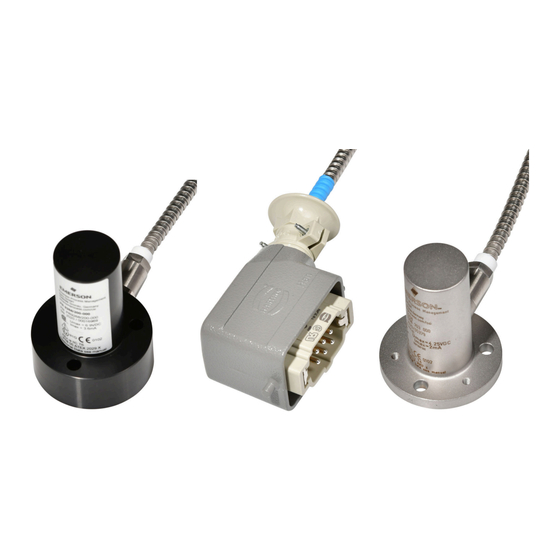
Installation Guide Application and design MHM-97479 November 2022 Application and design Application The electro-dynamic transducers PR 9268/01x-x00, PR 9268/20x−x00, PR 9268/30x−x00, PR 9268/60x−000, and PR 9268/70x−000 serve the measurement of absolute vibrations. They operate on the seismic measurement principle. A measuring coil, suspended on membrane springs, is the seismic mass of the transducer. - Page 14 Application and design Installation Guide November 2022 MHM-97479 Figure 3-1: PR 9268/01x-x00 A. Transducer PR 9268/018-900 without cable and C-5015 Plug B. Label C. Transducer with cable PR 9268/20x−x00 and PR 9268/30x−x00 A robust construction and a splash-proof housing permit the use of the transducer in hostile environments with temperatures up to 100°C.
- Page 15 Installation Guide Application and design MHM-97479 November 2022 Figure 3-2: PR 9268/ 20x−x00 and PR 9268/30x−x00 A. Harting connector B. Label C. Transducer PR 9268/60x−000 and PR 9268/70x−000 A robust construction and a splash-proof housing of stainless steel permit the use of the transducer in hostile environments with temperatures up to 200°C.
- Page 16 Application and design Installation Guide November 2022 MHM-97479 Table 3-3: Order matrix (continued) PR 9268/ Cable Armored 0 (3m), 1 (5m), 2 (8m), 3 (10) Non-armored 4 (3m), 5 (5m), 6 (8m), 7 (10) Cable End HARTING Figure 3-3: PR 9268/60x−000 and PR 9268/70x−000 A.
-
Page 17: Installation And Commissioning
Installation Guide Installation and commissioning MHM-97479 November 2022 Installation and commissioning Hints for installation and connection DANGER Do not expose the transducer to hard shocks and do not drop it. This could lead to internal damages and thus to impairment or loss of sensitivity. Mount the transducer on a flat and clean surface. - Page 18 Installation and commissioning Installation Guide November 2022 MHM-97479 Figure 4-2 Table 4-1 for wire colors of PR 9268/01x-x00 transducers with open cable end. The cable shield is not connected to the transducer housing. Figure 4-2: Wire colors – PR 9268/01x-x00 Table 4-1: Wire colors –...
- Page 19 Installation Guide Installation and commissioning MHM-97479 November 2022 Figure 4-4: PR 9268/018-900 – C-5015 plug A. 1: Signal A (high) B. 2: Signal B (low) Pin assignment Harting plug The pin assignment of the Harting plug of PR 9268/01x-000 transducers is as follows. Table 4-2: Pin assignment of Harting plug –...
- Page 20 Installation and commissioning Installation Guide November 2022 MHM-97479 Figure 4-5: Position of mounting threads All dimensions in mm. Install the cable without torsion and elongation and protect it against damage. If you install a transducer with a metal protection hose, use a clamp to fix the metal protection hose as closely as possible to the transducer.
- Page 21 Installation Guide Installation and commissioning MHM-97479 November 2022 Table 4-3: Wire colors – PR 9268/20x-x00 and PR 9268/30x-x00 (continued) Number Color Meaning Transducer housing Cable shield Figure 4-7 for circuit and connection diagram. Connect pin 5 of the Harting plug or the red wire to protective machine earth only if the transducer housing is mounted without earth-connection or due to national standards, with respect to Ex-i regulations or customer’s demands.
- Page 22 Install the Harting connector only in environments with temperatures not higher than 100°C. Do not open the connector. Emerson recommends to use the enclosed screws M6x20, washers, and spring washers to mount the transducers. The transducers have three through bores with a diameter of 6.6 mm and three M4 threaded holes for an alternative mounting option.
- Page 23 Installation Guide Installation and commissioning MHM-97479 November 2022 Figure 4-9: Connection diagram A. Transducer PR 9268/60x-000, PR 9268/70x-000 B. 3 m cable (standard) C. Harting plug D. Harting socket E. Sensitivity of 22.0 mV/(mm/s) for load 100 kΩ F. Sensitivity of 16.7 mV/(mm/s) for load 20 kΩ G.
-
Page 24: Csa - Conditions Of Acceptability
Installation and commissioning Installation Guide November 2022 MHM-97479 Figure 4-11: Connection PR 9268/60x-100-RAD and PR 9268/70x-100-RAD Table 4-4: Wire colors – all RAD types Number Wire color Meaning Black Signal high Brown Signal low Transducer housing White Cable shield CSA - Conditions of acceptability PR 9268/01x-x00 CAUTION The transducer PR 9268/01x−x00 may only be operated with devices that are sup-plied... -
Page 25: Installation Requirements Depending On Mounting Angle
(±60°). The transducers PR 9268/30x−x00 and PR 9268/70x−000 are specified for horizontal measurement (±30°). If the transducer is to be mounted in a direction different to the nominal measuring direction, Emerson recommends using a lifting or sinking current according to the angle deviation. The supplied current raises or drops the seismic mass of the sensor to keep it in the center of the movement range. -
Page 26: Pr 9268/20X-X00 And Pr 9268/60X-000 - Without Sinking Current
Installation and commissioning Installation Guide November 2022 MHM-97479 connector. For further information see sensor connection chapters in the manuals of the respective protection cards (for example, A6120 or A6500-SR). CAUTION To ensure proper measuring function, install the transducer only within the described mounting angle ranges. -
Page 27: Pr 9268/30X-X00 And Pr 9268/70X-000 - Without Lifting/Sinking Current
Installation Guide Installation and commissioning MHM-97479 November 2022 Figure 4-13: Deviation of ±60° from the nominal direction If the transducer is mounted in a position between -30° and -60° or +30° and +60°, a sinking current is necessary to lower the seismic mass of the transducer to the middle of the working range. -
Page 28: Pr 9268/30X-X00 And Pr 9268/70X-000 - With Lifting Current
Installation and commissioning Installation Guide November 2022 MHM-97479 Figure 4-14: Deviation of ±10° from the nominal direction A. Nominal position 4.3.4 PR 9268/30x-x00 and PR 9268/70x-000 – with lifting current The vibration transducers PR 9268/30x-x00 and PR 9268/70x-000 are designed for the horizontal measurement direction (90°... -
Page 29: Pr 9268/30X-X00 And Pr 9268/70X-000 - With Sinking Current
Installation Guide Installation and commissioning MHM-97479 November 2022 If the transducer is mounted in a position between -80° and -60° or 60° and 80° a lifting current is necessary to raise the seismic mass of the transducer to the middle of the working range. - Page 30 Installation and commissioning Installation Guide November 2022 MHM-97479 protection card (for example, A6120 or A6500-UM). The specified maximum sinking current for the PR 9268/30x-x00 is approximately 3.6 mA and for the PR 9268/70x-000 approximately 2.0 mA . These values are automatically used in the configuration when selecting the PR9268/30x-x00 or PR 9268/70x-000 from the sensor list of the configuration software.
-
Page 31: Maintenance, Fault Finding, And Repair
Installation Guide Maintenance, fault finding, and repair MHM-97479 November 2022 Maintenance, fault finding, and repair Maintenance The transducer does not require any maintenance during operation. Hints for fault finding CAUTION Any work on the system may impair machine protection. If a problem occurs, perform the tests described in Transducer resistance measurement, Insulation resistance... -
Page 32: Signal Generation Check
Depending on the movement, a voltage of approximately 1 V AC can be generated. PR 9268/70x-000 3. Reconnect the transducer or install a new one in case of a defect. Repair Repair or calibration is only possible at Emerson. MHM-97479, Rev. 3.6... -
Page 33: Technical Data
Installation Guide Technical data MHM-97479 November 2022 Technical data Only specifications with indicated tolerances or limit values are required. Data without tolerances or without error limits are informative data and not guaranteed. Technology is under constant development, and specifications are subject to change without notice. Measuring principle Common Low tuned measuring principle for absolute vibrations... -
Page 34: Operating Ranges
Technical data Installation Guide November 2022 MHM-97479 Operating ranges Common Vibration amplitude at nominal mounting ±1500 µm position 500 µm peak-peak (PR 9268/01x-x00) Limit stops ±2000 µm Permissible acceleration in measuring 10 g continuous, 20 g short-time direction Permissible acceleration in transverse direction Linearity error of sensitivity <2 %... - Page 35 Installation Guide Technical data MHM-97479 November 2022 Figure 6-1: Nomogram operating range MHM-97479, Rev. 3.6...
- Page 36 Technical data Installation Guide November 2022 MHM-97479 Figure 6-2: Nomogram operating range – PR 9268/01x-x00 Red lines: Limits of the PR 9268/01x-x00 transducer PR 9268/01x-x00 Frequency range 14 Hz to 1000 Hz Natural frequency 14 Hz Transverse sensitivity <0.1 g at 80 Hz MHM-97479, Rev.
-
Page 37: Electrical Data
Installation Guide Technical data MHM-97479 November 2022 Sensitivity 17.5 mV/(mm/s) ±8.5 % (nominal value at 20°C, 80 Hz, and 100 kΩ load) Dumping factor Approximately 0.6 PR 9268/20x-x00 and PR 9268/30x-x00 Frequency range 4 Hz to 1000 Hz Natural frequency 4.5 Hz ±0.75 Hz (at 20°C and 100 kΩ... -
Page 38: Environmental Conditions And Dimensions
Technical data Installation Guide November 2022 MHM-97479 Insulation resistance >1000 MΩ (test voltage <100 V DC) Recommended maximum lifting current 1.8 mA (PR 9268/20 maximum: 60° and PR 9268/30 for installation deviating from nominal maximum 30°) measuring direction PR 9268/60x-000 and 9268/70x-000 Resistance measuring circuit Measuring circuit pin 3 (statical) 3270 Ω... - Page 39 Installation Guide Technical data MHM-97479 November 2022 2-pole C-5051 plug (only PR 9268/018-900) Weight Sensor without cable approximately 280 g Figure 6-3: Dimensions – PR 9268/01x-x00 A. Green: signal high B. Blue: signal low C. Black: cable shield MHM-97479, Rev. 3.6...
- Page 40 Technical data Installation Guide November 2022 MHM-97479 Figure 6-4: Dimensions – PE 9268/018-900 Figure 6-5: Dimensions – mounting bolt PR 9268/20x-x00 and PR 9268/30x-x00 Operating Transducer without -20 to +100°C temperature connector Short time (<4 hours) up to 120°C range For connector -40 to +125°C MHM-97479, Rev.
- Page 41 Installation Guide Technical data MHM-97479 November 2022 Protection class IP 55 Housing Dimensions Figure 6-6 Material Al Mg Si Pb F28 Connector 6-pole Harting plug, 6-pole socket enclosed Weight Net weight, including approximately 930 g cable, connector, and plug) Transducer only approximately 260 g With packing approximately 1200 g...
- Page 42 Technical data Installation Guide November 2022 MHM-97479 Figure 6-6: Dimensions A. Harting socket B. 6-pole Harting connector C. Open cable end D. Cable construction details (see Table 3-2) E. Section on F-F (base only) All dimensions in mm. MHM-97479, Rev. 3.6...
- Page 43 Installation Guide Technical data MHM-97479 November 2022 PR 9268/60x-000 and 9268/70x-000 Operating Transducer without -20 to +200°C temperature connector Short time (<4 hours) up to 220°C range For connector -40 to +100°C Protection class IP 65 Housing Dimensions Figure 6-7 Material Stainless steel Connector...
- Page 44 Technical data Installation Guide November 2022 MHM-97479 Figure 6-7: Dimensions A. Harting socket B. Minimum bending radius for cable and protection tube = 35 mm C. Cable construction details (see Table 3-3) All dimensions in mm. MHM-97479, Rev. 3.6...
-
Page 45: Hazardous Location Installation
Installation Guide Hazardous location installation MHM-97479 November 2022 Hazardous location installation Version 1.2 Installation requirements Absolute vibration transducers of type PR 9268/20x-x00, PR 9268/30x-x00, PR 9268/60(0-3)-000, and PR 9268/70(0-3)-000 may be installed, depending on the type (see Table 7-1 Table 7-2), in hazardous areas zone 0/1 to 2, protection class intrinsic safety, provided, the following conditions are met. -
Page 46: Operation Requirements
Hazardous location installation Installation Guide November 2022 MHM-97479 Table 7-1: PR 9268/20x-x00 and PR 9268/30x-x0 – permissible types PR 9268/ Measure Vertical ment Horizontal Cable Armored 0 (3m), 1 (5m), 2 (8m), 3 (10) Non-armored 4 (3m), 5 (5m), 6 (8m), 7 (10) Cable End HARTING OPEN CABLE END Table 7-2: PR 9268/60x-000 and PR 9268/70x-000 –... - Page 47 Installation Guide Hazardous location installation MHM-97479 November 2022 Table 7-3: ATEX/IECEx PR 9268/20x-x00 and PR 9268/30x-x0 Standards EN IEC 60079-0:2018, Equipment - general requirements EN IEC 60079-11:2012, Intrinsically safe "i" EN IEC 60079-14:2014, Electrical installations design, selection and erection Identification 1G Ex ia IIC T6 ...
-
Page 48: Drawings
Hazardous location installation Installation Guide November 2022 MHM-97479 Drawings Figure 7-1: Connection example, intrinsically safe installation – PR 9268/20x-x00 and PR 9268/30x-x00 A. Safety barrier 9001/02−093−003−101 B. Potential equalizer C. Ex- hazardous area D. Non hazardous area E. Measurement amplifier MHM-97479, Rev. - Page 49 Installation Guide Hazardous location installation MHM-97479 November 2022 Figure 7-2: Connection example, potential free intrinsically safe installation with two safety barriers – PR 9268/20x-x00 and PR 9268/30x-x00 A. Safety barrier 9001/02−093−003−101 B. Safety barrier 9001/02−093−003−101 C. Potential equalizer D. Ex- hazardous area E.
-
Page 50: Revision History
Hazardous location installation Installation Guide November 2022 MHM-97479 Figure 7-3: Connection example, intrinsically safe installation – PR 9268/60x-000 and PR 9268/70x-000 A. Transmitter PR 9268/60x-000 or PR 9268/70x-000 B. 3m cable (standard) C. Harting plug D. Harting socket E. Sensitivity of 22.0 mV/(mm/s) for load 100 kΩ F. -
Page 51: Chapter 8 Certificates
Installation Guide Certificates MHM-97479 November 2022 Certificates MHM-97479, Rev. 3.6... - Page 52 Certificates Installation Guide November 2022 MHM-97479 MHM-97479, Rev. 3.6...
- Page 53 Installation Guide Certificates MHM-97479 November 2022 MHM-97479, Rev. 3.6...
- Page 54 Certificates Installation Guide November 2022 MHM-97479 MHM-97479, Rev. 3.6...
-
Page 55: Index
Installation Guide Index MHM-97479 November 2022 Index Connection CSA 7, 24, Current Lifting 25, Sinking 25, 26, Disposal Functional principle Measuring direction horizontal 27–29 vertical Nomogram RAD transducers Radiation resistance Seismic mass Sensitivity 15, Technical support MHM-97479, Rev. 3.6... - Page 56 Index Installation Guide November 2022 MHM-97479 MHM-97479, Rev. 3.6...
- Page 57 Installation Guide MHM-97479 November 2022 MHM-97479, Rev. 3.6...
- Page 58 The Emerson logo is a trademark and service mark of Emerson Electric Co. The AMS logo is a mark of one of the Emerson family of companies. All other marks are the property of their respective owners.
Need help?
Do you have a question about the Machinery Health PR 9268 Series and is the answer not in the manual?
Questions and answers