Table of Contents
Advertisement
Quick Links
Service Manual Part 1
[1]
PRODUCT OUTLINE ...................................................................................................... 1-1
[2]
CONSUMABLE PARTS .................................................................................................. 2-1
[3]
UPGRADING AND MIGRATING ............................................................................................ 3-1
[4]
REPLACING PARTS AND SUPPLIES .......................................................................... 4-1
[5]
PARTS LIST ....................................................................................................................... 5-1
Service Manual Part 2 ........................................................................................................1
Parts marked with "
" are important for maintaining the safety of the set. Be sure to replace these parts
with specified ones for maintaining the safety and performance of the set.
SERVICE MANUAL
DIGITAL FULL COLOR
LASER PRINTER
MODEL
CONTENTS
SHARP CORPORATION
CODE:00ZMXC507PS2E
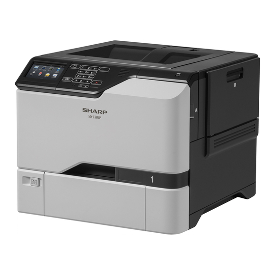
MX-C507P
This document has been published to be used
for after sales service only.
The contents are subject to change without notice.
Advertisement
Table of Contents

Related Manuals for Sharp MX-C507P


Summary of Contents for Sharp MX-C507P
- Page 1 SERVICE MANUAL CODE:00ZMXC507PS2E DIGITAL FULL COLOR LASER PRINTER MX-C507P MODEL CONTENTS Service Manual Part 1 PRODUCT OUTLINE ...................... 1-1 CONSUMABLE PARTS ....................2-1 UPGRADING AND MIGRATING .................... 3-1 REPLACING PARTS AND SUPPLIES ................4-1 PARTS LIST ........................5-1 Service Manual Part 2 ......................1 Parts marked with "...
- Page 2 ● (Local Option) L2057X0085 Security module ● SPD0001 Surge protector (100V) ● (Local Option) SPD0002 Surge protector (200V) ● (Local Option) 57X0300 Contact authentication device ● (Local Option) 57X0301 Contactless authentication device ● (Local Option) MX-C507P [1] PRODUCT OUTLINE 1-1...
- Page 3 ● (Local Option) 57X0085 Security module ● (Local Option) SPD0001 Surge protector (100V) ● (Local Option) SPD0002 Surge protector (200V) ● (Local Option) 57X0300 Contact authentication device ● (Local Option) 57X0301 Contactless authentication device ● (Local Option) MX-C507P [1] PRODUCT OUTLINE 1-2...
- Page 4 Europe, Middle East, India Item Model name Content Number Life Fuser maintenance kit (220-240V) MX-C50FK Fuser 220V 150K Pick roller Separator pad Transfer module MX-C50TK Transfer module 150K Toner Collection Container MX-C50HB Waste Toner Bottle MX-C507P [2] CONSUMABLE PARTS 2-1...
- Page 5 2. Using a flat-head screwdriver, remove the controller board access cover. Warning—Potential Damage: Controller board electronic components are easily damaged by static electricity. Touch a metal surface on the printer before touching any controller board components or connectors. MX-C507P [3] UPGRADING AND MIGRATING 3-1...
- Page 6 3. Unpack the memory card. Warning—Potential Damage: Avoid touching the connection points along the edge of the card. 4. Insert the memory card until it clicks into place. MX-C507P [3] UPGRADING AND MIGRATING 3-2...
- Page 7 2. Using a flat-head screwdriver, remove the controller board access cover. Warning—Potential Damage: Controller board electronic components are easily damaged by static electricity. Touch a metal surface on the printer before touching any controller board electronic components or connectors. MX-C507P [3] UPGRADING AND MIGRATING 3-3...
- Page 8 3. Unpack the internal solutions port (ISP) kit. Mounting bracket Thumbscrews Housing MX-C507P [3] UPGRADING AND MIGRATING 3-4...
- Page 9 ISP extended cable 4. Install the ISP into its housing. MX-C507P [3] UPGRADING AND MIGRATING 3-5...
- Page 10 5. Attach the housing to the controller board access cover. 6. Connect the ISP extended cable to the ISP connector in the controller board. MX-C507P [3] UPGRADING AND MIGRATING 3-6...
- Page 11 2. Using a flat-head screwdriver, remove the controller board access cover. Warning—Potential Damage: Controller board electronic components are easily damaged by static electricity. Touch a metal surface on the printer before touching any components or connectors. MX-C507P [3] UPGRADING AND MIGRATING 3-7...
- Page 12 Note: The entire length of the connector on the card must touch and be flush against the controller board. Warning—Potential Damage: Improper installation of the card may cause damage to the card and the controller board. MX-C507P [3] UPGRADING AND MIGRATING 3-8...
- Page 13 2. Using a flat-head screwdriver, remove the controller board access cover. Warning—Potential Damage: Controller board electronic components are easily damaged by static electricity. Touch a metal surface on the printer before touching any controller board electronic components or connectors. MX-C507P [3] UPGRADING AND MIGRATING 3-9...
- Page 14 3. Unpack the hard disk. 4. Attach the hard disk to the controller board. Warning—Potential Damage: Do not touch or press the center of the hard disk. MX-C507P [3] UPGRADING AND MIGRATING 3-10...
- Page 15 5. Open door B. 6. Open door C. MX-C507P [3] UPGRADING AND MIGRATING 3-11...
- Page 16 10. Connect the power cord to the electrical outlet, and then turn on the printer. CAUTION—POTENTIAL INJURY: To avoid the risk of fire or electrical shock, connect the power cord to an appropriately rated and properly grounded electrical outlet that is near the product and easily accessible. MX-C507P [3] UPGRADING AND MIGRATING 3-12...
- Page 17 6. Turn on the printer. Add the tray in the print driver to make it available for print jobs. For more information, see Adding available options in the print driver. MX-C507P [3] UPGRADING AND MIGRATING 3-13...
- Page 18 3. Apply the changes. Firmware Exporting or importing a configuration file You can export the configuration settings of your printer into a text file, and then import the file to apply the settings to other printers. MX-C507P [3] UPGRADING AND MIGRATING 3-14...
- Page 19 For more information on updating the device firmware, contact your sales representative. 1. From the Embedded Web Server, click Settings >Device >Update Firmware. 2. Browse to locate the required flash file. 3. Apply the changes. MX-C507P [3] UPGRADING AND MIGRATING 3-15...
- Page 20 [4] Replacing parts and supplies Replacing the imaging unit 1. Open door B. 2. Remove the waste toner bottle. MX-C507P [4] REPLACING PARTS AND SUPPLIES 4-1...
- Page 21 Warning—Potential Damage: Do not expose the photoconductor unit to direct light for more than 10 minutes. Extended exposure to light may cause print quality problems. Warning—Potential Damage: Do not touch the shiny photoconductor drum under the imaging kit. Doing so may affect the quality of future print jobs. MX-C507P [4] REPLACING PARTS AND SUPPLIES 4-2...
- Page 22 6. Unpack the new imaging unit. 7. Insert the new imaging unit. 8. Insert the black toner cartridge. MX-C507P [4] REPLACING PARTS AND SUPPLIES 4-3...
- Page 23 9. Insert the imaging kit. 10. Insert the waste toner bottle. 11. Close door B. MX-C507P [4] REPLACING PARTS AND SUPPLIES 4-4...
- Page 24 Replacing the imaging kit 1. Open door B. 2. Remove the waste toner bottle. MX-C507P [4] REPLACING PARTS AND SUPPLIES 4-5...
- Page 25 Warning—Potential Damage: Do not expose the photoconductor unit to direct light for more than 10 minutes. Extended exposure to light may cause print quality problems. Warning—Potential Damage: Do not touch the shiny photoconductor drum under the imaging unit. Doing so may affect the quality of future print jobs. MX-C507P [4] REPLACING PARTS AND SUPPLIES 4-6...
- Page 26 Note: The black imaging unit includes the black developer unit and photoconductor unit. 7. Insert the black imaging unit into the new imaging kit. 8. Insert the toner cartridges. MX-C507P [4] REPLACING PARTS AND SUPPLIES 4-7...
- Page 27 2. Open doors A and D. CAUTION—HOT SURFACE: The inside of the printer might be hot. To reduce the risk of injury from a hot component, allow the surface to cool before touching it. MX-C507P [4] REPLACING PARTS AND SUPPLIES 4-8...
- Page 28 CAUTION—POTENTIAL INJURY: To avoid the risk of fire or electrical shock, connect the power cord to an appropriately rated and properly grounded electrical outlet that is near the product and easily accessible. 8. Reset the fuser maintenance counter. For more information, see Resetting the maintenance counter. MX-C507P [4] REPLACING PARTS AND SUPPLIES 4-9...
- Page 29 Replacing the pick roller in the 550-sheet tray 1. Turn off the printer, and then unplug the power cord from the electrical outlet. 2. Remove the tray. 3. Remove the pick roller. 4. Unpack the new pick roller. MX-C507P [4] REPLACING PARTS AND SUPPLIES 4-10...
- Page 30 Replacing the pick roller in the multipurpose feeder 1. Turn off the printer, and then unplug the power cord from the electrical outlet. 2. Open the multipurpose feeder. MX-C507P [4] REPLACING PARTS AND SUPPLIES 4-11...
- Page 31 CAUTION—POTENTIAL INJURY: To avoid the risk of fire or electrical shock, connect the power cord to an appropriately rated and properly grounded electrical outlet that is near the product and easily accessible. Replacing the separator pad 1. Pull out the tray. MX-C507P [4] REPLACING PARTS AND SUPPLIES 4-12...
- Page 32 4. Insert the new separator pad until it clicks into place. 5. Insert the tray. Replacing the transfer module 1. Turn off the printer, and then unplug the power cord from the electrical outlet. MX-C507P [4] REPLACING PARTS AND SUPPLIES 4-13...
- Page 33 2. Open door B. 3. Remove the waste toner bottle. MX-C507P [4] REPLACING PARTS AND SUPPLIES 4-14...
- Page 34 4. Remove the imaging kit. 5. Open door A. CAUTION—HOT SURFACE: The inside of the printer might be hot. To reduce the risk of injury from a hot component, allow the surface to cool before touching it. MX-C507P [4] REPLACING PARTS AND SUPPLIES 4-15...
- Page 35 6. Remove the transfer module. 7. Unpack the new transfer module, and then remove the packing material. 8. Insert the new transfer module. 9. Close door A. MX-C507P [4] REPLACING PARTS AND SUPPLIES 4-16...
- Page 36 14. Reset the maintenance counter. For more information, see Resetting the maintenance counter. Resetting the maintenance counter 1. From the home screen, touch Settings >Device >Maintenance >Configuration Menu >Supply Usage And Counters. Select Fuser Reset or ITM Reset. MX-C507P [4] REPLACING PARTS AND SUPPLIES 4-17...
- Page 37 [5] PARTS LIST (MX-C507P) Manufacture parts Section Section name Asm-index Sharp parts number Description number 1 Assembly 1 Covers 1 0SP41X0773/// 41X0773 Output bin exit cover Output bin flag 2 Assembly 1 Covers 1 0SP41X0772/// 41X0772 3 Assembly 1 Covers 1...
- Page 38 Fuser (100 V), Pick roller, Separator pad Fuser maintenance kit, type 00, 110–120 V 133 Assembly 15 Maintenance kits 41X0554 Not applicable for MX-C507P Fuser (110 V), Pick roller, Separator pad Fuser maintenance kit, type 01, 220–240 V 134 Assembly 15 Maintenance kits...
- Page 39 Republic, Egypt, Estonia, France, Germany, Greece, 151 Assembly 16 Power cords 40X1767 Hungary, Iceland, Italy, Latvia, Lithuania, Morocco, Poland, Portugal, Romania, Russia (CIS), Serbia, Not applicable for MX-C507P Slovakia, Spain, Turkey 152 Assembly 16 Power cords 40X1774 Nordics 153 Assembly 16...
- Page 40 MX-C507P Service Manual Part 2 • Start diagnostics • Maintenance • Safety and notices • Trademarks • Index Table of contents...
- Page 41 5028...
- Page 42 5028 Table of contents Notices, conventions, and safety information........13 Laser notice............................13 Conventions............................16 Safety information............................. 17 General caution statements....................... 22 General information................29 Finding the serial number......................29 Paper and specialty media guide....................30 Paper guidelines ..........................
-
Page 43: Table Of Contents
240 paper jams ............................116 241 paper jams ............................128 242–244 paper jams ..........................139 User attendance messages....................... 164 Non‑Sharp supply ........................164 31 user attendance errors ......................... 164 32 user attendance errors ........................165 33 user attendance errors ........................166 42 user attendance errors ........................ - Page 44 5028 88 user attendance errors ......................... 174 Non-supply user attendance errors ....................175 Printer hardware errors ........................189 100 errors ..............................189 102 errors ..............................195 110 errors ................................197 120 errors ..............................198 121 errors ..............................200 126-127 errors ............................204 128 errors ............................
- Page 45 5028 Mobile solutions module NFC service check ..................257 Network service check ........................258 Toner meter cycle (TMC) card service check ..................261 USB service check ........................262 Control panel USB cable service check ..................... 262 Toner patch sensing service check ....................263 Auto alignment service check......................
- Page 46 5028 Disconnecting ribbon cables......................297 Adjustments..........................297 Printhead alignment adjustment ......................297 Registration adjustment ........................299 Removal procedures......................... 302 Cover removals......................... 303 Front cover removal .......................... 303 Top cover removal ..........................305 Left cover removal ..........................308 Right cover removal ...........................
- Page 47 5028 TMC card removal ..........................352 Motor (duplex/MPF) removal ........................352 Motor (fuser) removal ..........................355 HVPS removal ..........................356 Sensor (MPF paper present) removal ....................... 359 Waste toner bottle idler gear removal ..................... 361 Imaging unit cover removal ........................361 Sensor (TPS) removal .........................
- Page 48 5028 550‑sheet tray paper feeder removal ....................... 418 Sensor (550-sheet tray pass-through) removal ..................419 Sensor (550-sheet tray trailing edge) removal .................. 420 Sensor (550-sheet tray paper size) removal ..................420 550-sheet tray controller board assembly removal ................422 550-sheet tray interface cable removal .................... 423 550-sheet tray empty sensor actuator removal ................
- Page 49 5028 Assembly 11: 550‑sheet tray option 1....................477 Assembly 12: 550‑sheet tray option 2.................... 479 Assembly 13: Adjustable stand....................... 481 Assembly 14: Miscellaneous parts................... 483 Assembly 15: Maintenance kits...................... 485 Assembly 16: Power cords....................... 487 Printer specifications.
- Page 50 5028 Index....................521 Table of contents...
- Page 51 5028 Table of contents...
- Page 52 5028 Notices, conventions, and safety information Laser notice The printer is certified in the U.S. to conform to the requirements of DHHS 21 CFR, Chapter I, Subchapter J for Class I (1) laser products, and elsewhere is certified as a Class I laser product conforming to the requirements of IEC 60825-1: 2014.
- Page 53 5028 Aviso sobre laser Esta impressora foi certificada nos EUA por estar em conformidade com os requisitos do DHHS 21 CFR capítulo I, subcapítulo J, para produtos a laser de Classe I (1) e, nos demais países, foi certificada como um produto a laser de Classe I em conformidade com os requisitos da IEC 60825-1: 2014.
- Page 54 5028 Laser-Hinweis Der Drucker wurde in den USA zertifiziert und entspricht den Anforderungen der Vorschriften DHHS 21 CFR Kapitel I für Laserprodukte der Klasse I (1), andernorts ist er als Laserprodukt der Klasse I zertifiziert, das den Anforderungen von IEC 60825-1: 2014 entspricht. Laserprodukte der Klasse I werden nicht als gefährlich betrachtet.
- Page 55 5028 ナンス、または所定のサービス条件の下で、ユーザーがクラス I レベルを超えるレーザー放射に絶対にさらされない ように設計されています。 레이저 고지사항 프린터는 미국에서 레이저 제품용 DHHS 21 CFR Chapter I, Subchapter J의 요구 사항을 준수하며 이외 지역 에서 IEC 60825-1: 2014의 요구 사항을 준수하는 클래스 I(1) 레이저 제품으로 승인되었습니다. Class I 레이저 제품은 위험한 제품으로 간주되지 않습니다. 프린터에는 650~670 나노미터 범위의 파장 영역 에서...
- Page 56 5028 CAUTION—ROTATING FAN BLADES: Indicates a risk of laceration from moving fan blades. Safety information • The safety of this product is based on testing and approvals of the original design and specific components. The manufacturer is not responsible for safety in the event of use of unauthorized replacement parts. •...
- Page 57 5028 PRECAUCIÓ. PERILL DE DESCÀRREGA ELÈCTRICA: Quan vegeu aquest símbol, indica que hi ha un perill de voltatge elevat en l'àrea del producte on esteu treballant. Desconnecteu el producte abans de començar o tingueu precaució si el producte ha de rebre alimentació per realitzar la tasca. PRECAUCIÓ.
- Page 58 5028 • Le informazioni di manutenzione per questo prodotto sono state predisposte per essere utilizzate da un tecnico dell'assistenza professionale e non sono state previste per l'uso da parte di altre persone. • È possibile che vi sia un maggior rischio di scosse elettriche e lesioni personali durante lo smontaggio e la manutenzione di questo prodotto.
- Page 59 5028 FORSIGTIG - RISIKO FOR SKADE: Litium-batteriet i dette produkt er ikke beregnet til at blive udskiftet. Der er fare for eksplosion, hvis et litium-batteri udskiftes forkert. Du må ikke genoplade, demontere eller afbrænde et litium-batteri. Brugte litium-batterier skal bortskaffes i overensstemmelse med producentens instruktioner og lokale retningslinjer.
- Page 60 5028 FORSIKTIG – FARE FOR STØT: Dette symbolet betyr at det er fare for farlig spenning i det området av produktet der du arbeider. Koble fra produktet før du begynner, eller vær forsiktig hvis produktet må ha strøm for å kunne utføre oppgaven. FORSIKTIG –...
- Page 61 5028 주의—감전 위험: 이 기호가 표시된 경우 작업 중인 제품 주변에서 위험 전압 위험이 있습니다. 사용 전/후에 전원 코드를 뽑아 두시고 제품에서 작업을 수행하는 데 반드시 전원이 필요한 경우에는 주의 하여 사용하십시오. 주의—상해 위험: 이 제품에 들어 있는 리튬 배터리는 교체할 수 없습니다. 리튬 배터리를 잘못 교체 하면...
- Page 62 5028 Descriptions in page 23 to 28 are not applicable to this model. Therefore it was deleted. 23 - 28...
- Page 63 5028 General information The MX-C507P is network‑capable, A4 laser printers that print both color and monochrome print jobs. Model Configurations MX-C507P 4.3-in. color touch screen display, duplex print, networking “Diagnost ics and troubleshooting” on pag e 37. For For information on diagnosing a problem, see information on removing and reinstalling parts, see “Part s removal”...
- Page 64 5028 Paper and specialty media guide Paper guidelines Paper characteristics The following paper characteristics affect print quality and reliability. Consider these factors before printing on them: Weight “Supported paper types and weights” on page Curl Curl is the tendency for paper to curl at its edges. Excessive curl can cause paper feeding problems. Curl can occur after the paper passes through the printer, where it is exposed to high temperatures.
- Page 65 5028 To help avoid paper jams and poor print quality: • Always use new, undamaged paper. • Before loading paper, know the recommended printable side of the paper. This information is usually indicated on the paper package. • Do not use paper that has been cut or trimmed by hand. •...
- Page 66 5028 Note: A combination of high humidity (over 60%) and high printing temperature may wrinkle or seal envelopes. Tips on using labels • From the printer control panel, set the paper size, type, texture, and weight in the Paper menu to match the labels loaded in the tray.
- Page 67 5028 Supported paper sizes, types, and weights The following tables provide information on standard and optional paper sources and the sizes, types, and weights of paper they support. Note: For an unlisted paper size, select the closest larger listed size. Supported paper sizes Paper sizes supported by the trays and multipurpose feeder Two‑sided...
- Page 68 5028 Paper size Dimensions 550‑sheet tray Multipurpose feeder Two‑sided printing 10 Envelope 105 x 241 mm (4.1 x 9.5 in.) Monarch Envelope 98.4 x 190.5 mm (3.9 x 7.5 in.) 98 x 162 mm (3.9 x 6.4 in.) to Other Envelope 176 x 250 mm (6.9 x 9.8 in.) Universal 104.8 x 148 mm (4.13 x 5.83 in.)
- Page 69 5028 Data security notice Identifying printer memory • Volatile memory—The printer uses standard random access memory (RAM) to buffer user data temporarily during simple print and copy jobs. • Non-volatile memory—The printer may use two forms of non-volatile memory: EEPROM and NAND (flash memory).
- Page 70 5028 • #1 Phillips screwdriver, magnetic • #2 Phillips screwdriver, magnetic • #2 Phillips screwdriver, magnetic short-blade • 7/32 inch (5.5 mm) open-end wrench • 7.0 mm nut driver • Needle‑nose pliers • Diagonal side cutters • Spring hook • Feeler gauges •...
- Page 71 5028 Diagnostics and troubleshooting CAUTION—SHOCK HAZARD: To avoid the risk of electrical shock and to prevent damage to the printer, remove the power cord from the electrical outlet before you connect or disconnect any cable or electronic card or assembly for personal safety and to prevent damage to the printer. Disconnect any connections between the printer and computers or peripherals.
- Page 72 5028 The progress bar appears on the splash screen. The printer begins to POST, and the motors and sensors are polled and tested. The home screen displays. Printer calibration may begin. Note: If any of the tests fail, the printer displays an error code. Fixing print quality issues Initial print quality check Before troubleshooting print problems, perform the following:...
- Page 73 5028 Actions Step 1 Go to step 3. Go to step 2. From the home screen, touch Settings > Device > Preferences. Check if the paper type and size settings match the paper type and size set on the tray. Do the settings match? Step 2 Go to step 3.
- Page 74 5028 Background or gray background check Leading edge ABCDE ABCDE ABCDE Trailing edge Action Step 1 Go to step 2. Go to step 3. From the home screen, touch Settings > Reports > Device > Device Statistics. Check the status of the imaging unit if it was recently replaced. Does the status show that the imaging unit was recently replaced? Step 2 Go to step 3.
- Page 75 5028 Action Step 8 Go to step 9. The problem is solved. Remove the printhead, and then clean the printhead lenses. See “Printhead removal” on page 397. Does the problem remain? Step 9 Contact the next The problem is level of support. solved.
- Page 76 5028 Action Step 5 Go to step 6. The problem is solved. • If the affected color is cyan, magenta, or yellow, then replace the developer unit of the affected color. • If the affected color is black, then replace the imaging unit. Does the problem remain? Step 6 Go to step 8.
- Page 77 5028 Action Step 13 Go to step 14. The problem is solved. Replace the cable. Does the problem remain? Step 14 Go to step 15. The problem is solved. “Printhead removal” on page 397. Replace the printhead. See Does the problem remain? Step 15 Contact the next The problem is...
- Page 78 5028 Action Step 4 Go to step 5. The problem is solved. • If the affected color is cyan, magenta, or yellow, then replace the developer unit of the affected color. • If the affected color is black, then replace the imaging unit. Does the problem remain? Step 5 Contact the next...
- Page 79 5028 Actions Step 6 Go to step 7. The problem is solved. Remove the imaging kit, and then clean the printhead lenses. See “Cleaning the printhead lenses” on page 451. Does the problem remain? Step 7 Go to step 8. The problem is solved.
- Page 80 5028 Actions Step 3 Go to step 4. Go to step 5. Enter the Diagnostics menu, and then navigate to: Advanced Print Quality Samples > Advanced Print Quality Samples Check if the lines appear on the same area of the page. Do the lines appear on the same area? Step 4 Go to step 5.
- Page 81 5028 Actions Step 2 Contact the next The problem is level of support. solved. Change the paper size and type, or adjust the size settings in the tray. Does the problem remain? Mottled print and dots check Action Step 1 Go to step 3.
- Page 82 5028 Action Step 7 Go to step 8. The problem is solved. • If the affected color is cyan, magenta, or yellow, then replace the developer unit of the affected color. • If the affected color is black, then replace the imaging unit. Does the problem remain? Step 8 Go to step 10.
- Page 83 5028 Action Step 2 Go to step 6. Go to step 3. Enter the Diagnostics menu, and then navigate to: Advanced Print Quality Samples > Advanced Print Quality Samples Check the test page. Did the print defect appear on all the pages? Step 3 Go to step 5.
- Page 84 5028 Action Step 1 Go to step 3. Go to step 2. From the home screen, touch Settings > Paper > Size/Type. Select the paper source. Check if the paper type and size settings match the paper type and size set on the tray. Do the settings match? Step 2 Go to step 3.
-
Page 85: Solid Color Or Black Image Check
5028 Action Step 8 Go to step 9. Contact the next level of support. From the home screen, touch Settings > Reports > Menu Settings Page. Note: Perform this step twice to clear any debris. Check the fuser assembly for toner contamination. Is there toner contamination? Step 9 Contact the next... - Page 86 5028 Action Step 4 Go to step 5. Go to step 6. Place a narrow strip of paper over the gap between the developers. Note: Make sure that the paper stays in place when reinstalling the imaging unit to prevent the laser from discharging the photoconductors.
-
Page 87: Vertical Colored Lines Or Banding Check
5028 Vertical colored lines or banding check Leading edge ABCDE ABCDE ABCDE Trailing edge Action Step 1 Go to step 2. Go to step 4. Enter the Diagnostics menu, and then navigate to: Advanced Print Quality Samples > Advanced Print Quality Samples Check the test page. -
Page 88: Image Void Scan Direction Check
5028 Image void scan direction check Action Step 1 Go to step 2. The problem is solved. Load paper from a fresh package. Note: Paper may absorb moisture due to high humidity. Store paper in its original wrapper until it is ready to be used. Does the problem remain? Step 2 Go to step 3. -
Page 89: Image Void Process Direction Check
5028 Action Step 9 Go to step 10. The problem is solved. Replace the controller board. See “Controller board removal” on page 393. Does the problem remain? Step 10 Contact the next The problem is level of support. solved. Replace the printhead. See “Printhead removal”... -
Page 90: Dark Print Check
5028 Action Step 7 Go to step 8. The problem is solved. Remove the dust or debris. Does the problem remain? Step 8 Go to step 9. The problem is solved. • If the affected color is cyan, magenta, or yellow, then replace the developer unit of the affected color. - Page 91 5028 Action Step 3 Go to step 4. Go to step 11. Enter the Diagnostics menu, and then navigate to: Advanced Print Quality Samples > Advanced Print Quality Samples Check the test page. Is only one color affected? Step 4 Go to step 5.
-
Page 92: Missing Color Check
5028 Action Step 11 Go to step 12. Go to step 13. Check the electrical contacts on the transfer module for damage. Are the contacts on the belt damaged? Step 12 Go to step 13. The problem is solved. “Transfer module removal” on Replace the transfer module. - Page 93 5028 Action Step 4 Go to step 5. The problem is solved. Open the toner access door, and then pull down the developer unit release mechanism. Does the problem remain? Step 5 Go to step 6. The problem is solved. Reconnect the printhead cable connector on the controller board.
- Page 94 5028 Action Step 9 Go to step 10. The problem is solved. Replace the transfer module. See “Transfer module removal” on page 371. Does the problem remain? Step 10 Go to step 12. Go to step 11. Check the contacts on the imaging unit and the developer of the missing color for dust or debris.
-
Page 95: Uneven Print Density Check
5028 Action Step 17 Go to step 19. Go to step 18. While manually turning the motors, check if the couplers that drive the imaging kit move. Do the couplers move? Step 18 Go to step 19. The problem is solved. -
Page 96: Repeating Defects Check
5028 Action Step 3 Go to step 4. Go to step 5. Check the paper for texture or rough finish. Is the paper textured or rough? Step 4 Go to step 5. The problem is solved. Replace the textured or rough paper with plain paper. Does the problem remain? Step 5 Go to step 6. - Page 97 5028 Action Step 4 Contact the next The problem is level of support. solved. • If the affected color is cyan, magenta, or yellow, then replace the developer unit of the affected color. • If the affected color is black, then replace the imaging unit. Does the problem remain? Step 5 Go to step 6.
-
Page 98: Random Marks Check
5028 Random marks check Action Step 1 Go to step 2. Go to step 3. Check the printer for toner leaks. Are there toner leaks? Step 2 Go to step 3. The problem is solved. Clean the printer thoroughly using a toner vacuum. Perform a print job to clear the remaining toner from the imaging components. -
Page 99: Light Print Check
5028 Light print check Action Step 1 Go to step 2. Go to step 3. Remove the transfer module. See “Transfer module removal” on page 371. Check if the three contacts are visible and if they freely move. Are the contacts visible and do they freely move? Step 2 Go to step 4. - Page 100 5028 Action Step 5 Go to step 6. The problem is solved. Adjust the darkness setting to the proper value. Does the problem remain? Step 6 Go to step 7. Go to step 15. Enter the Diagnostics menu, and then navigate to: Advanced Print Quality Samples >...
- Page 101 5028 Action Step 13 Go to step 14. The problem is solved. Check the motor cable for proper installation, and reseat if necessary. Does the problem remain? Step 14 Go to step 15. The problem is solved. Replace the motor. See “Motor (EP drive) removal”...
-
Page 102: Skewed Print Service Check
5028 Action Step 22 Go to step 23. The problem is solved. Replace the transfer module. See “Transfer module removal” on page 371. Does the problem remain? Step 23 Contact the next The problem is level of support. solved. Replace the HVPS. See “HVPS removal”... - Page 103 5028 Action Step 7 Go to step 8. The problem is solved. Check the cable on the JMTR1 connector on the controller board for proper connection and damage, and replace if necessary. Does the problem remain? Step 8 Go to step 9. The problem is solved.
- Page 104 5028 Action Step 12 Contact the next The problem is level of support. solved. Inspect the ITU for missing and damaged or defective hardware. If necessary, replace the ITU. Check if the E‑clip (A) is not missing. Check if the bearing (B) is properly seated. Does the problem remain? Diagnostics and troubleshoo ting...
-
Page 105: Marks On Leading Or Trailing Edges Check
5028 Marks on leading or trailing edges check Action Step 1 Go to step 2. Go to another print quality check. Check the leading and trailing edges of the printout for marks. Does the printout have marks on the leading or trailing edges? Step 2 Contact the next The problem is... -
Page 106: Paper Jams
5028 Action Step 1 Go to step 2. The problem is solved. Make sure that the image on your original document does not print directly over the area where the tag (A) is present. • Sample RFID media Note: This image shows a typical RFID tag. The actual tag varies in size, shape, and appearance, as well as position and orientation on the page. - Page 107 5028 Correct loading of paper Incorrect loading of paper • Do not load or remove a tray while the printer is printing. • Do not load too much paper. Make sure that the stack height is below the maximum paper fill indicator. •...
-
Page 108: Identifying Jam Locations
5028 • Make sure that the paper size and type are set correctly on the computer or printer control panel. • Store paper according to manufacturer recommendations. Identifying jam locations Notes: • When Jam Assist is set to On, the printer flushes blank pages or pages with partial prints after a jammed page has been cleared. -
Page 109: Paper Jam In Trays
5028 Paper jam in trays Pull out the tray. Warning—Potential Damage: A sensor inside the optional tray is easily damaged by static electricity. Touch a metal surface before removing the jammed paper in the tray. Remove the jammed paper. Note: Make sure that all paper fragments are removed. Insert the tray. -
Page 110: Paper Jam In The Multipurpose Feeder
5028 Paper jam in the multipurpose feeder Remove paper from the multipurpose feeder. Pull out the tray. Remove the jammed paper. Note: Make sure that all paper fragments are removed. Insert the tray. Paper jam in the standard bin Remove the jammed paper. Note: Make sure that all paper fragments are removed. -
Page 111: Paper Jam In Door A
5028 Open doors A and D, and then remove any paper fragments. CAUTION—HOT SURFACE: The inside of the printer might be hot. To reduce the risk of injury from a hot component, allow the surface to cool before touching it. Close doors D and A. - Page 112 5028 Open the fuser access door. Remove the jammed paper. Note: Make sure that all paper fragments are removed. Close door A. Diagnostics and troubleshooting...
- Page 113 5028 Paper jam in the duplex unit Open door A. CAUTION—HOT SURFACE: The inside of the printer might be hot. To reduce the risk of injury from a hot component, allow the surface to cool before touching it. Open the duplex cover. Remove the jammed paper.
-
Page 114: Paper Jams
5028 200 paper jams 200 paper jam messages Error code Description Action “Sensor (input): Paper failed to clear 200.05 Paper fed from the MPF never cleared the sensor (input). service check” on page “Sensor (input): Paper arrived too early 200.12 Paper fed from tray 1 was detected earlier than expected at the sensor (input). - Page 115 5028 Sensor (input): Paper arrived too early service check Action Step 1 Go to step 3. Go to step 2. From the home screen, touch Settings > Device > Preferences. Check if the paper size matches the size set on the tray guides. Does the paper size match the size set on the tray? Step 2 Go to step 3.
- Page 116 5028 Action Step 2 Go to step 3. The problem is solved. Change the paper size or adjust the size setting in the tray. Does the problem remain? Step 3 Go to step 5. Go to step 4. Check the paper path for paper jams and fragments. Is the paper path free of jams and fragments? Step 4 Go to step 5.
- Page 117 5028 Action Step 10 Contact the next Go to step 11. level of support. Enter the Diagnostics menu, and then navigate to: Printer diagnostics & adjustments > Motor tests > Deskew Touch Start. Does the motor run? Step 11 Go to step 12. The problem is solved.
- Page 118 5028 Action Step 6 Go to step 7. The problem is solved. Check the sensor cable for proper connection and damage, and replace if necessary. Does the problem remain? Step 7 Go to step 8. The problem is solved. Check the sensor for damage, and replace if necessary. Does the problem remain? Step 8 Contact the next...
- Page 119 5028 Action Step 4 Go to step 5. The problem is solved. Remove the excess paper from the tray. Does the problem remain? Step 5 Go to step 6. Go to step 7. Check the paper condition in the tray. Is the paper crumpled or damaged? Step 6 Go to step 7.
-
Page 120: Paper Jams
5028 Action Step 2 Go to step 3. The problem is solved. Change the paper size or adjust the size setting in the tray. Does the problem remain? Step 3 Go to step 5. Go to step 4. Check the paper path for partially fed or jammed paper. Is the paper path free of partially fed or jammed paper? Step 4 Go to step 5. - Page 121 5028 Sensor (fuser buckle) jam service check Action Step 1 Go to step 3. Go to step 2. From the home screen, touch Settings > Device > Preferences. Check if the paper size matches the size set on the tray guides. Does the paper size match the size set on the tray? Step 2 Go to step 3.
-
Page 122: Paper Jams
5028 202 paper jams 202 paper jam messages Error code Description Action “Sensor (fuser exit): Paper arrived too 202.12 Paper fed from tray 1 was detected earlier than expected at the sensor (fuser exit). early service check” on page “Sensor (fuser exit): Paper failed to arrive 202.13 Paper fed from tray 1 never arrived at the sensor (fuser exit). - Page 123 5028 Sensor (fuser exit): Paper arrived too early service check Action Step 1 Go to step 3. Go to step 2. From the home screen, touch Settings > Device > Preferences. Check if the paper size matches the size set on the tray guides. Does the paper size match the size set on the tray? Step 2 Go to step 3.
- Page 124 5028 Action Step 2 Go to step 3. The problem is solved. Change the paper size or adjust the size setting in the tray. Does the problem remain? Step 3 Go to step 5. Go to step 4. Check the paper path for paper jams and fragments. Is the paper path free of jams and fragments? Step 4 Go to step 5.
- Page 125 5028 Action Step 11 Go to step 12. The problem is solved. Check the transfer belt for damage and replace if necessary. See “Transfer module removal” on page 371. Does the problem remain? Step 12 Go to step 15. Go to step 13. Enter the Diagnostics menu, and then navigate to: Printer diagnostics &...
- Page 126 5028 Sensor (fuser exit): Paper failed to clear service check Action Step 1 Go to step 3. Go to step 2. From the home screen, touch Settings > Device > Preferences. Check if the paper size matches the size set on the tray guides. Does the paper size match the size set on the tray? Step 2 Go to step 3.
- Page 127 5028 Action Step 9 Go to step 10. The problem is solved. Make sure that the fuser is seated properly. Check the cable on the JFSNS connector on the controller board for proper connection, and reseat if necessary. Does the problem remain? Step 10 Go to step 11.
- Page 128 5028 Action Step 3 Go to step 5. Go to step 4. Check the fuser rollers for damage. Are the rollers free of damage? Step 4 Go to step 5. The problem is solved. “Fuser removal” on page 370. Replace the fuser. See Does the problem remain? Step 5 Go to step 8.
-
Page 129: Paper Jams
5028 Action Step 3 Go to step 5. Go to step 4. Check the paper path for partially fed or jammed paper. Is the paper path free of partially fed or jammed paper? Step 4 Go to step 5. The problem is solved. -
Page 130: Paper Jams
5028 Action Step 2 Go to step 3. The problem is solved. Change the paper size or adjust the size setting in the tray. Does the problem remain? Step 3 Go to step 5. Go to step 4. Check the paper path for partially fed or jammed paper. Is the paper path free of partially fed or jammed paper? Step 4 Go to step 5. - Page 131 5028 Sensor (narrow media) static jam service check Action Step 1 Go to step 3. Go to step 2. From the home screen, touch Settings > Device > Preferences. Check if the paper size matches the size set on the tray guides. Does the paper size match the size set on the tray? Step 2 Go to step 3.
-
Page 132: Paper Jams
5028 221 paper jams 221 paper jam messages Error code Description Action “Sensor (duplex path 1) static jam 221.xx Paper in the paper path of the redrive area remains detected at the sensor (duplex path 1) service check” on page when the printer is turned on. -
Page 133: Paper Jams
5028 Action Step 7 Contact the next The problem is level of support. solved. Check the sensor for damage, and replace if necessary. See “Sensor (redrive) removal” on page 390. Perform a print job. Does the problem remain? 230 paper jams 230 paper jam messages Error code Description... - Page 134 5028 Error code Description Action “Sensor (duplex path 1): Paper cleared 230.44 Paper fed from tray 4 cleared the sensor (duplex path 1) earlier than expected. too early service check” on page 104. 230.45 Paper fed from tray 4 never cleared the sensor “Sensor (duplex path 1): Paper failed to (duplex path 1).
- Page 135 5028 Action Step 2 Go to step 3. The problem is solved. Change the paper size or adjust the size setting in the tray. Does the problem remain? Step 3 Go to step 5. Go to step 4. Check the redrive paper path for paper jams and obstructions. Is the paper path free of jams and obstructions? Step 4 Go to step 5.
- Page 136 5028 Action Step 11 Go to step 13. Go to step 12. Enter the Diagnostics menu, and then navigate to: Printer diagnostics & adjustments > Sensor tests Find the sensor (Duplex path 1). Does the sensor status change while toggling the sensor? Step 12 Go to step 13.
- Page 137 5028 Action Step 4 Go to step 5. The problem is solved. Change the paper size or adjust the size setting in the tray. Does the problem remain? Step 5 Go to step 7. Go to step 6. Check the paper path for paper jams and obstructions. Is the paper path free of jams and obstructions? Step 6 Go to step 7.
- Page 138 5028 Action Step 12 Contact the next The problem is level of support. solved. “Motor (duplex/MPF) removal” on Replace the motor. See page 352. Perform a print job. Does the problem remain? Sensor (duplex path 1): Paper cleared too early service check Action Step 1 Go to step 3.
-
Page 139: Paper Jams
5028 Action Step 8 Contact the next The problem is level of support. solved. Perform a print job. Does the problem remain? 231 paper jams 231 paper jam messages Error code Description Action 231.12 Paper fed from tray 1 was detected earlier than “Sensor (duplex path 2): Paper arrived expected at the sensor (duplex path 2). - Page 140 5028 Sensor (duplex path 2): Paper arrived too early service check Action Step 1 Go to step 3. Go to step 2. From the home screen, touch Settings > Device > Preferences. Check if the paper size matches the size set on the tray guides. Does the paper size match the size set on the tray? Step 2 Go to step 3.
- Page 141 5028 Action Step 3 Go to step 5. Go to step 4. Check the duplex paper path for paper jams and obstructions. Is the paper path free of jams and obstructions? Step 4 Go to step 5. The problem is solved.
- Page 142 5028 Action Step 11 Go to step 12. The problem is solved. Check the duplex drive gears in the printer for damage, and replace if necessary. Does the problem remain? Step 12 Contact the next The problem is level of support. solved.
- Page 143 5028 Action Step 7 Go to step 10. Go to step 8. Enter the Diagnostics menu, and then navigate to: Printer diagnostics & adjustments > Sensor tests Find the sensor (Duplex path 2). Does the sensor status change while toggling the sensor? Step 8 Go to step 9.
- Page 144 5028 Action Step 2 Go to step 3. The problem is solved. Change the paper size or adjust the size setting in the tray. Does the problem remain? Step 3 Go to step 5. Go to step 4. Check the duplex rollers for damage. Are the rollers free of damage? Step 4 Go to step 5.
-
Page 145: Paper Jams
5028 Action Step 2 Go to step 3. The problem is solved. Change the paper size or adjust the size setting in the tray. Does the problem remain? Step 3 Go to step 5. Go to step 4. Check the paper path for partially fed or jammed paper. Is the paper path free of partially fed or jammed paper? Step 4 Go to step 5. - Page 146 5028 Error code Description Action “Sensor (duplex path 2) static jam 232.91 Paper remains detected at the sensor (duplex path 2) after the printer is turned on. service check” on page 110. Sensor (MPF/pass‑through): Paper (duplex job) failed to arrive service check Action Step 1 Go to step 3.
- Page 147 5028 Action Step 9 Go to step 10. The problem is solved. Check the sensor cable for proper connection and damage, and replace if necessary. Does the problem remain? Step 10 Go to step 11. The problem is solved. Replace the isolation unit. See “Isolation unit removal”...
- Page 148 5028 Sensor (MPF/pass‑through): Paper (duplex job) failed to clear service check Action Step 1 Go to step 3. Go to step 2. From the home screen, touch Settings > Device > Preferences. Check if the paper size matches the size set on the tray guides. Does the paper size match the size set on the tray? Step 2 Go to step 3.
- Page 149 5028 Action Step 10 Contact the next Go to step 11. level of support. Enter the Diagnostics menu, and then navigate to: Printer diagnostics & adjustments > Motor tests > Deskew Touch Start. Does the motor run? Step 11 Go to step 12. The problem is solved.
-
Page 150: Paper Jams
5028 Action Step 5 Go to step 8. Go to step 6. Enter the Diagnostics menu, and then navigate to: Printer diagnostics & adjustments > Sensor tests Find the sensor (Input). Does the sensor status change while toggling the sensor? Step 6 Go to step 7. - Page 151 5028 Error code Description Action “Motor (duplex/MPF) jam service 240.82 The motor (duplex/MPF) has stalled. check” on page 127. 240.84 The motor (duplex/MPF) failed to achieve expected speed or has stalled. 240.91 Paper remains detected at the sensor (MPF/pass- “Sensor (MPF/pass-through) static jam through) after the printer is turned on.
- Page 152 5028 Action Step 8 Go to step 9. Contact the next level of support. Check the sensor and sensor flag for damage. Is the sensor or sensor flag damaged? Step 9 Contact the next The problem is level of support. solved.
- Page 153 5028 Action Step 8 Go to step 9. The problem is solved. Replace the pick rollers. Does the problem remain? Step 9 Go to step 11. Go to step 10. Check the pick rollers for proper installation. Firmly press the pick roller assembly upward to make sure that it is properly engaged to the shaft.
- Page 154 5028 Action Step 17 Contact the next Go to step 18. level of support. Enter the Diagnostics menu, and then navigate to: Printer diagnostics & adjustments > Motor tests > Duplex/MPF Select a setting, and then touch Start. Does the motor run? Step 18 Go to step 19.
- Page 155 5028 Action Step 6 Go to step 7. The problem is solved. Replace the crumpled or damaged paper. Does the problem remain? Step 7 Go to step 9. Go to step 8. Check the condition of the tray 2 pick rollers. Are the pick rollers free from excess wear, contamination, and damage? Step 8...
- Page 156 5028 Action Step 15 Go to step 16. The problem is solved. Check the sensor for damage, and replace if necessary. Does the problem remain? Step 16 Go to step 19. Go to step 17. Enter the Diagnostics menu, and then navigate to: Printer diagnostics &...
- Page 157 5028 Action Step 3 Go to step 6. Go to step 4. Enter the Diagnostics menu, and then navigate to: Printer diagnostics & adjustments > Sensor tests Find the sensor (MPF/pass‑through). Does the sensor status change while toggling the sensor? Step 4 Go to step 5.
- Page 158 5028 Action Step 11 Contact the next The problem is level of support. solved. “Motor Replace the motor (550-sheet tray pass‑through). See (550-sheet tray pass‑through) removal” on page 416. Perform a print job. Does the problem remain? Sensor (MPF/pass-through): Paper (tray 4) failed to arrive service check Action Step 1 Go to step 3.
- Page 159 5028 Action Step 8 Go to step 11. Go to step 9. Enter the Diagnostics menu, and then navigate to: Printer diagnostics & adjustments > Sensor tests Find the sensor (Pass‑through (tray 2)). Does the sensor status change while toggling the sensor? Step 9 Go to step 10.
- Page 160 5028 Action Step 15 Go to step 16. The problem is solved. Check the motor cable for proper connection and damage, and replace if necessary. Does the problem remain? Step 16 Go to step 17. The problem is solved. Replace the motor (550-sheet tray pass‑through). See “Motor (550-sheet tray pass‑through) removal”...
- Page 161 5028 Action Step 3 Contact the next Go to step 4. level of support. Enter the Diagnostics menu, and then navigate to: Printer diagnostics & adjustments > Sensor tests Find the sensor (MPF/pass‑through). Does the sensor status change while toggling the sensor? Step 4 Go to step 5.
-
Page 162: Paper Jams
5028 Action Step 6 Go to step 7. Go to step 8. Check the duplex and MPF paper path exiting tray 1. Is the paper path free of fragments and contamination? Step 7 Go to step 8. The problem is solved. - Page 163 5028 Error code Description Action “Tray actuator and spring service 241.84 Failed to pick last sheet of paper. check” on page 137. 241.91 Paper remains detected at the sensor (tray 1 pick) “Sensor (tray 1 pick) static jam service after the printer is turned on. check”...
- Page 164 5028 Action Step 8 Go to step 9. The problem is solved. Check the sensor for damage and replace if necessary. See “Sensor (input) removal” on page 378. Does the problem remain? Step 9 Contact the next Go to step 10. level of support.
- Page 165 5028 Action Step 5 Go to step 6. Go to step 7. Check the paper condition in tray 1. Is the paper crumpled or damaged? Step 6 Go to step 7. The problem is solved. Replace the crumpled or damaged paper. Does the problem remain? Step 7 Go to step 9.
- Page 166 5028 Action Step 14 Go to step 15. The problem is solved. Check the sensor cable for proper connection and damage, and replace if necessary. Does the problem remain? Step 15 Go to step 16. The problem is solved. Check the sensor for damage, and replace if necessary. See “Sensor (input) removal”...
- Page 167 5028 Action Step 2 Go to step 3. The problem is solved. Change the paper size or adjust the size setting in the tray. Does the problem remain? Step 3 Go to step 4. Go to step 5. Check the tray for overfilling. Is the tray overfilled? Step 4 Go to step 5.
- Page 168 5028 Action Step 4 Go to step 5. The problem is solved. Remove the excess paper from the tray. Does the problem remain? Step 5 Go to step 6. Go to step 7. Check the paper condition in the tray. Is the paper crumpled or damaged? Step 6 Go to step 7.
- Page 169 5028 Action Step 2 Go to step 3. The problem is solved. Change the paper size or adjust the size setting in the tray. Does the problem remain? Step 3 Contact the next Go to step 4. level of support. Enter the Diagnostics menu, and then navigate to: Printer diagnostics &...
- Page 170 5028 Action Step 5 Go to step 7. Go to step 6. Check the paper path exiting the tray. Is the paper path free of fragments and contamination? Step 6 Go to step 7. The problem is solved. Clean the paper path. Does the problem remain? Step 7 Contact the next...
- Page 171 5028 Tray actuator and spring service check Action Step 1 Go to step 3. Go to step 2. Remove the imaging kit. Remove the affected tray insert. Remove the pick roller from the tray. Place the printer on its side. Check if the spring (A) on the flag is installed properly.
- Page 172 5028 Action Step 2 Go to step 4. Go to step 3. “550-sheet tray Remove the tray empty sensor actuator. See empty sensor actuator removal” on page 424. Reseat the spring (B) on the flag as shown. Reinstall the flag. “Media feeder removal”...
-
Page 173: Paper Jams
5028 Action Step 3 Contact the next The problem is level of support. solved. “Media feeder removal” on Replace the media feeder. See page 411. Perform a feed test until the tray is out of paper. Does the problem remain? Step 4 Contact the next The problem is... - Page 174 5028 Error code Description Action “Sensor (tray 2 pass-through): Paper 242.33 Paper fed from tray 3 never arrived at the sensor (tray 2 pass-through). failed to arrive service check” on page 147. 242.34 Paper fed from tray 3 cleared the sensor (tray 2 “Sensors (tray [x] trailing edge and pass-through) or the sensor (tray 2 trailing edge) pass-through): Paper cleared too early...
- Page 175 5028 Error code Description Action “Sensor (tray 2 pass-through): Paper 242.93 Paper never arrived at the sensor (tray 2 pass- through). Paper source is undetermined. failed to arrive service check” on page 147. 242.94 Paper cleared the sensor (tray 2 pass-through) or “Sensors (tray [x] trailing edge and the sensor (tray 2 trailing edge) earlier than pass-through): Paper cleared too early...
- Page 176 5028 Error code Description Action “Sensors (tray [x] trailing edge and 243.42 Paper fed from tray 4 was detected earlier than pass‑through): Paper arrived too early expected at the sensor (tray 3 pass-through) or at the sensor (tray 3 trailing edge). service check”...
- Page 177 5028 244 paper jam messages Error code Description Action 244.41 Paper fed from tray 4 remains detected at the “Sensors (tray [x] trailing edge and pass- sensor (tray 4 pass‑through) or at the sensor (tray through) static jam service check” on 4 trailing edge) after the printer is turned on.
- Page 178 5028 Error code Description Action “Sensors (tray [x] trailing edge and pass- 244.98 Paper was detected later than expected at the sensor (tray 4 pass-through) or at the sensor (tray through): Paper arrived too late service 4 trailing edge). Paper source is undetermined. check”...
- Page 179 5028 Action Step 8 Go to step 11. Go to step 9. Enter the Diagnostics menu, and then navigate to: Additional input tray diagnostics > Sensor tests Find the sensor (Pass-through (tray [x])). Does the sensor status change while toggling the sensor? Step 9 Go to step 11.
- Page 180 5028 Action Step 5 Go to step 8. Go to step 6. Enter the Diagnostics menu, and then navigate to: Additional input tray diagnostics > Sensor tests Find the sensor (Trailing edge (tray [x])). Does the sensor status change while toggling the sensor? Step 6 Go to step 8.
- Page 181 5028 Sensor (tray 2 pass-through): Paper failed to arrive service check Action Step 1 Go to step 3. Go to step 2. From the home screen, touch Settings > Device > Preferences. Check if the paper size matches the size set on the tray guides. Does the paper size match the size set on the tray? Step 2 Go to step 3.
- Page 182 5028 Action Step 11 Go to step 14. Go to step 12. Enter the Diagnostics menu, and then navigate to: Additional input tray diagnostics > Sensor tests Find the sensor (Pass-through (tray 2)). Does the sensor status change while toggling the sensor? Step 12 Go to step 14.
- Page 183 5028 Action Step 19 Go to step 20. The problem is solved. Reinstall or replace the motor. See “Motor (550-sheet tray pass‑through) removal” on page 416. Does the problem remain? Step 20 Contact the next The problem is level of support. solved.
- Page 184 5028 Action Step 8 Go to step 9. The problem is solved. Replace the crumpled or damaged paper. Does the problem remain? Step 9 Go to step 11. Go to step 10. Check the paper path for partially fed or jammed paper. Is the paper path free of partially fed or jammed paper? Step 10 Go to step 11.
- Page 185 5028 Action Step 16 Go to step 17. The problem is solved. Reinstall or replace the motor. See “Motor (550-sheet tray pass‑through) removal” on page 416. Does the problem remain? Step 17 Go to step 20. Go to step 18. Enter the Diagnostics menu, and then navigate to: Additional input tray diagnostics >...
- Page 186 5028 Action Step 4 Go to step 5. The problem is solved. Replace the paper or change the paper size setting in the tray. Does the problem remain? Step 5 Go to step 6. Go to step 7. Check the paper tray for overfilling. Is the paper tray overfilled? Step 6 Go to step 7.
- Page 187 5028 Action Step 13 Go to step 15. Go to step 14. Reseat the sensor cable, and then check the sensor for misalignment and damage. Is the sensor properly installed and free of damage? Step 14 Go to step 15. The problem is solved.
- Page 188 5028 Action Step 7 Go to step 10. Go to step 8. Enter the Diagnostics menu, and then navigate to: Additional input tray diagnostics > Sensor tests Find the sensor (Trailing edge (tray [x])). Does the sensor status change while toggling the sensor? Step 8 Go to step 10.
- Page 189 5028 Action Step 15 Go to step 16. The problem is solved. Reinstall or replace the sensor. See “Sensor (550-sheet tray pass- through) removal” on page 419. Does the problem remain? Step 16 Go to step 19. Go to step 17. Enter the Diagnostics menu, and then navigate to: Additional input tray diagnostics >...
- Page 190 5028 Action Step 4 Go to step 5. The problem is solved. Replace the paper or change the paper size setting in the tray. Does the problem remain? Step 5 Go to step 6. Go to step 7. Check the paper tray for overfilling. Is the paper tray overfilled? Step 6 Go to step 7.
- Page 191 5028 Action Step 13 Go to step 15. Go to step 14. Check the paper path exiting the paper tray. Is the paper path free of fragments and contamination? Step 14 Go to step 15. The problem is solved. Clean the paper path. Does the problem remain? Step 15 Go to step 18.
- Page 192 5028 Action Step 21 Go to step 22. The problem is solved. Replace the media feeder. See “Media feeder removal” on page 411. Does the problem remain? Step 22 Contact the next The problem is level of support. solved. Perform a print test. Does the problem remain? Sensors (tray [x] trailing edge and pass‑through): Paper failed to clear service check Action...
- Page 193 5028 Action Step 7 Go to step 8. The problem is solved. Reinstall or replace the sensor. See “Sensor (550-sheet tray trailing edge) removal” on page 420. Does the problem remain? Step 8 Go to step 11. Go to step 9. Enter the Diagnostics menu, and then navigate to: Printer diagnostics &...
- Page 194 5028 Action Step 15 Go to step 17. Go to step 16. Reseat the motor cable, and then check the motor for misalignment and damage. Is the motor properly installed and free of damage? Step 16 Go to step 17. The problem is solved.
- Page 195 5028 Action Step 7 Go to step 8. Go to step 9. Check the paper condition in the tray. Is the paper crumpled or damaged? Step 8 Go to step 9. The problem is solved. Replace the crumpled or damaged paper. Does the problem remain? Step 9 Go to step 11.
- Page 196 5028 Action Step 16 Go to step 18. Go to step 17. Reseat the sensor cable, and then check the sensor for misalignment and damage. Is the sensor properly installed and free of damage? Step 17 Go to step 18. The problem is solved.
- Page 197 5028 Action Step 24 Go to step 25. The problem is solved. Reinstall or replace the sensor. See “Sensor (550-sheet tray pass- through) removal” on page 419. Does the problem remain? Step 25 Go to step 28. Go to step 26. Enter the Diagnostics menu, and then navigate to: Additional input tray diagnostics >...
-
Page 198: User Attendance Messages
The printer has detected a non‑Sharp supply or part installed in the printer. The Sharp printer is designed to function best with genuine Sharp supplies and parts. Use of third-party supplies or parts may affect the performance, reliability, or life of the printer and its imaging components. -
Page 199: User Attendance Errors
All fuser sensors are out of range. Reinstall the “Fuser service check” on page 203. fuser. Z code: • 31.xxN— Non-genuine Sharp supply 32 user attendance errors 32 user attendance error messages Error code Description Action “Missing toner, developer, or 32.40z... -
Page 200: User Attendance Errors
33.50z Non-Sharp black developer. The smart chip contents have been manipulated by a third party manufacturer. 33.64z Non-Sharp color imaging unit. The smart chip contents have been manipulated by a third party manufacturer. Z codes: • 33.xxA— Non-genuine Sharp supply •... - Page 201 5028 Action Step 2 Go to step 3. The problem is solved. Remove the imaging kit, and then inspect the springs for damage or improper contact. If necessary, reposition the springs. Check cables for poor connection. If necessary, reconnect the cables.
-
Page 202: User Attendance Errors
5028 Action Step 10 Contact the next The problem is level of support. solved. Replace the controller board. See “Controller board removal” on page 393. Does the problem remain? 42 user attendance errors 42 user attendance error messages Error code Description Action 42.xyK... -
Page 203: User Attendance Errors
5028 43 user attendance errors 43 user attendance error messages Error code Description Action “Toner meter cycle (TMC) card service 43.41z Cyan bottle TMC error. check” on page 261. 43.42z Magenta bottle TMC error. 43.43z Yellow bottle TMC error. z codes: •... -
Page 204: User Attendance Errors
5028 Maintenance kit service check Action Warning—Potential Damage: Do not perform this step if the Contact the next The problem is printer is on. level of support. solved. Replace the required maintenance kit. Reset the maintenance counter. See “Resetting the maintenance counter”... -
Page 205: User Attendance Errors
5028 Action Step 5 Go to step 6. The problem is solved. Remove the dust or debris. Does the problem remain? Step 6 Contact the next The problem is level of support. solved. Check the waste toner contact block for proper connection and damage, and replace if necessary. -
Page 206: User Attendance Errors
5028 84 user attendance errors 84 user attendance error messages Error code Description Action “Cartridge or photoconductor error service 84.01 The imaging kit is nearly low. The photoconductor threshold has been reached. check” on page 174. 84.09 The imaging kit is nearly low. The user-selected EWS set point has been reached. -
Page 207: User Attendance Errors
5028 85 user attendance errors 85 user attendance error messages Error code Description Action “Cartridge or photoconductor error service 85.01 The black imaging unit is nearly low. The photoconductor threshold has been reached. check” on page 174. 85.09 The black imaging unit is nearly low. The user‑selected EWS set point has been reached. - Page 208 5028 88 user attendance errors 88 user attendance error messages Error code Description Action “Cartridge or photoconductor error service 88.01z The cartridge is nearly low. The TMC threshold has been reached. check” on page 174. 88.09z The cartridge is nearly low. The user‑selected EWS set point has been reached.
- Page 209 5028 Action Step 2 Go to step 3. The problem is solved. Make sure that the cartridge or photoconductor is properly installed. Make sure that the cartridge or photoconductor cables are properly connected. Does the problem remain? Step 3 Go to step 4. The problem is solved.
- Page 210 5028 Error code Description Action “Insufficient flash memory service check” Flash memory is full. on page 185. Unformatted flash memory. “Flash memory failure service check” on page 184. Serial port or network error. “Flash memory failure service check” on page 184.
- Page 211 5028 Insufficient memory service check Action Step 1 Go to step 2. The problem is solved. Reset the printer, and then navigate to: Paper Menu > Print Settings > Download Target > Disk Does the problem remain? Step 2 Go to step 3. The problem is solved.
- Page 212 5028 Error on every page service check Action Step 1 Go to step 3. Go to step 2. Check if the media loaded has an RFID tag (A) attached or embedded. • Sample RFID media Note: This image shows a typical RFID tag. The actual tag varies in size, shape, and appearance, as well as position and orientation on the page.
- Page 213 5028 Action Step 4 Go to step 5. The problem is solved. Load the RFID media into Tray 3 or Tray 4. Does the problem remain? Step 5 Go to step 7. Go to step 6. Check if the printer, driver, or job settings are selecting the tray that holds the RFID media.
- Page 214 5028 Error on some pages service check Action Step 1 Go to step 3. Go to step 2. Check if the media loaded has an RFID tag (A) attached or embedded. • Sample RFID media Note: This image shows a typical RFID tag. The actual tag varies in size, shape, and appearance, as well as position and orientation on the page.
- Page 215 5028 Action Step 5 Go to step 7. Go to step 6. Check if the printer, driver, or job settings are selecting the tray that holds the RFID media. Do the settings specify Tray 3 or Tray 4? Step 6 Go to step 7.
- Page 216 5028 Action Step 11 Contact the next The problem is level of support. solved. Make sure that all pages are in the correct and similar orientation. Does the problem remain? Step 12 Contact the next The problem is level of support. solved.
- Page 217 5028 Action Step 2 Go to step 3. The problem is solved. Install the RFID Option in a Tray 2 position. Install at least one optional tray below the RFID option. Does the problem remain? Step 3 Go to step 4. Go to step 5.
- Page 218 5028 Action Step 10 Contact the next The problem is level of support. solved. Replace the RFID Option. • 41X1379 (low voltage, North America) • 41X1613 (high voltage, EMEA) Does the problem remain? Flash memory failure service check Action Step 1 Go to step 2.
- Page 219 5028 Insufficient flash memory service check Action Step 1 Go to step 3. Go to step 2. Navigate to Settings > Print settings > Utilities Menu > Format Flash > Yes. Does the problem remain? Step 2 Go to step 3. The problem is solved.
- Page 220 5028 Action Step 4 Contact the next The problem is level of support. solved. Make sure that the printer is using the latest firmware version, and update if necessary. Does the problem remain? Disabled port service check Action Step 1 Go to step 2.
- Page 221 5028 Excess options service check Action Step 1 Go to step 2. The problem is solved. Perform a POR, and then resend the print job. Does the problem remain? Step 2 Go to step 3. The problem is solved. If applicable, make sure that the internal option is supported. Does the problem remain? Step 3 Go to step 6.
- Page 222 5028 Incompatible hardware option service check Action Step 1 Go to step 2. The problem is solved. CAUTION—SHOCK HAZARD: Do not perform this step if the printer is on. Reseat the hardware option cables. Check the cables for damage, and replace if necessary. Does the problem remain? Step 2 Go to step 3.
- Page 223 5028 Action Step 3 Go to step 4. The problem is solved. Make sure that the hard disk cable is properly installed. Check the cable for damage, and replace if necessary. Does the problem remain? Step 4 Go to step 5. The problem is solved.
- Page 224 5028 Error code Description Action “Sensor (duplex/MPF input) service 100.35 The following sensors appear to be disconnected: check” on page 194. Sensor (MPF paper present) Sensor (duplex path 2) Sensor (fuser buckle) Sensor (narrow media) 100.36 The MPF paper present sensor is unplugged. 100.37 The duplex path 2 sensor is unplugged.
- Page 225 5028 Fuser sensors service check Action Step 1 Go to step 2. Go to step 3. Check the error that appeared. Is the error 100.4? Step 2 Go to step 3. The problem is solved. Check the sensor (fuser nip) for proper connection, and reseat if necessary.
- Page 226 5028 Tray 1 sensor (media out) cable is unplugged service check Action Step 1 Go to step 2. The problem is solved. Check the cable on the JMTR1 connector on the controller board for proper connection, and reseat if necessary. Does the problem remain? Step 2 Go to step 3.
- Page 227 5028 Lower paper path sensors service check Action Step 1 Go to step 3. Go to step 2. Check the error that appeared. Is the error 100.41? Step 2 Go to step 10. Go to step 3. Check the error that appeared. Is the error 100.44? Step 3 Go to step 5.
- Page 228 5028 Action Step 10 Go to step 11. The problem is solved. Check the red cables connecting the JPKSNS1 connector to the sensor (input) for proper connection and damage, and replace if necessary. Does the problem remain? Step 11 Contact the next The problem is level of support.
- Page 229 5028 Action Step 6 Contact the next The problem is level of support. solved. Check the sensors for damage, and replace if necessary. Does the problem remain? 102 errors 102 error messages Error code Description Action 102.20 Tray 2 product ID is invalid. “Invalid input option type or ID is detected service check”...
- Page 230 5028 Action Step 4 Go to step 6. Go to step 5. Check the printer interface cable and adjacent options for damage. Are the cable and options free of damage? Step 5 Go to step 6. The problem is solved. Replace the cable and options.
- Page 231 5028 110 errors 110 error messages Error code Description Action “Printhead service check” on page 197. 110.20 The printhead error was detected before the motor was turned on. 110.21 The printhead power was off when the laser servo started. 110.31 The printhead error (no first Hysnc) was detected.
- Page 232 5028 Action Step 3 Go to step 4. The problem is solved. Reconnect the cables. Does the problem remain? Step 4 Go to step 5. The problem is solved. Check the printhead cable for damage, and replace if necessary. Does the problem remain? Step 5 Go to step 6.
- Page 233 5028 Motor (fuser) service check Action Step 1 Go to step 2. The problem is solved. Reset the printer. Does the problem remain? Step 2 Go to step 3. Go to step 4. Check the fuser for damage or life expiration, and replace if necessary.
- Page 234 5028 121 errors 121 error messages Error code Description Action “Fuser service check” on page 203. 121.00 Fuser failed to reach the temperature during warm‑up. 121.01 There was an attempt to heat fuser, but it was not installed. 121.02 Fuser went over the required temperature during EWC/line voltage detection.
- Page 235 5028 Error code Description Action 121.20 Fuser did not reach the required temperature “Fuser service check” on page 203. during steady state control. 121.21 Fuser low power trace heating rate exceeded error threshold. 121.22 Open fuser relay was detected. 121.23 Fuser reached the required temperature during final EWC/line voltage detection too late.
- Page 236 5028 Error code Description Action 121.41 Fuser mechanism did not detect the expected cam “Fuser service check” on page 203. sensor signal. 121.42 Fuser gate time increasing out of control. 121.48 Fuser type does not match the fuser driver. 121.50 Fuser went over the required temperature during global over temperature check.
- Page 237 5028 Error code Description Action 121.81 Open fuser backup roll thermistor was detected. “Fuser service check” on page 203. 121.82 Open fuser second backup roll thermistor was detected. 121.83 Open fuser narrow media backup roll thermistor was detected. 121.84 Non‑contact sensor (BUR) is missing. 121.86 Fuser backup roll thermistor temperature is out of range.
- Page 238 5028 Action Step 5 Go to step 6. The problem is solved. Check the cable for damage, and replace if necessary. Does the problem remain? Step 6 Go to step 7. The problem is solved. Check the fuser cable for proper connection and damage, and replace if necessary.
- Page 239 5028 LVPS service check Action Step 1 Go to step 2. The problem is solved. Reset the printer. Does the problem remain? Step 2 Go to step 4. Go to step 3. Check the LVPS cable on the JLVPS connector on the controller board for proper connection.
- Page 240 5028 Action Step 3 Go to step 4. The problem is solved. Reconnect the cable. Does the problem remain? Step 4 Go to step 5. The problem is solved. Check the cable for damage, and replace if necessary. Does the problem remain? Step 5 Go to step 6.
- Page 241 5028 Action Step 4 Go to step 5. The problem is solved. Replace the sensor (TPS). See “Sensor (TPS) removal” on page 362. Does the problem remain? Step 5 Contact the next The problem is level of support. solved. Replace the controller board. See “Controller board removal”...
- Page 242 5028 Action Step 3 Go to step 5. Go to step 4. Manually turn the drive gears. Do the black developer and transfer module drive gears freely turn? Step 4 Go to step 5. The problem is solved. Replace the motor (EP drive). See “Motor (EP drive) removal”...
- Page 243 5028 144 errors 144 error messages Error code Description Action “Motor (Y developer) service check” on 144.80 The motor (Y developer) did not turn on. page 209. 144.81 The motor (Y developer) did not turn off. 144.82 The motor (Y developer) speed did not ramp up to the required level.
- Page 244 5028 Action Step 5 Contact the next The problem is level of support. solved. Check the imaging kit components and transfer module for damage or life expiration, and replace if necessary. Does the problem remain? Step 6 Go to step 8. Go to step 7.
- Page 245 5028 145 errors 145 error messages Error code Description Action “Motor (BOR) service check” on 145.80 The motor (BOR) did not turn on. page 211. 145.81 The motor (BOR) did not turn off. 145.82 The motor (BOR) speed did not ramp up to the required level.
- Page 246 5028 Action Step 5 Go to step 7. Go to step 6. Check the cable on the motor and on the JBOR1 connector on the controller board for proper connection. Is the cable properly connected at both ends? Step 6 Go to step 7.
- Page 247 5028 Motor (deskew) service check Action Step 1 Go to step 2. The problem is solved. Reset the printer. Does the problem remain? Step 2 Go to step 3. Go to step 5. Enter the Diagnostics menu, and then navigate to: Printer diagnostics &...
- Page 248 5028 149 errors 149 error messages Error code Description Action “Motor (output) service check” on 149.80 The motor (output) did not turn on. page 214. 149.81 The motor (output) did not turn off. 149.82 The motor (output) speed did not ramp up to the required level.
- Page 249 5028 Action Step 6 Contact the next The problem is level of support. solved. Replace the controller board. See “Controller board removal” on page 393. Does the problem remain? 150 and 160 errors 150 and 160 error messages Error code Description Action 150.80 The motor (duplex/MPF) did not turn on.
- Page 250 5028 Motor (duplex/MPF) service check Action Step 1 Go to step 2. The problem is solved. Reset the printer. Does the problem remain? Step 2 Go to step 3. Go to step 5. Enter the Diagnostics menu, and then navigate to: Printer diagnostics &...
- Page 251 5028 151 errors 151 error messages Error code Description Action “Motor (K developer) service check” on 151.80 The motor (K developer) did not turn on. page 217. 151.81 The motor (K developer) did not turn off. 151.82 The motor (K developer) speed did not ramp up to the required level.
- Page 252 5028 Action Step 5 Contact the next The problem is level of support. solved. Check the imaging kit components and transfer module for damage or life expiration, and replace if necessary. Does the problem remain? Step 6 Go to step 8. Go to step 7.
- Page 253 5028 153 errors 153 error messages Error code Description Action “Isolation unit service check” on 153.80 The isolation unit did not turn on. page 219. 153.81 The isolation unit did not turn off. 153.82 The isolation unit speed did not ramp up to the required level.
- Page 254 5028 Action Step 6 Go to step 7. The problem is solved. Reconnect the cable. Does the problem remain? Step 7 Go to step 8. The problem is solved. Check the cable for damage, and replace if necessary. Does the problem remain? Step 8 Contact the next The problem is...
- Page 255 5028 162 error messages Error code Description Action 162.80 The motor (tray 2 pick) did not turn on. “Tray pick roller assembly and lift motor service check” on page 223. 162.81 The motor (tray 2 pick) did not turn off. 162.82 The motor (tray 2 pick) speed did not ramp up to the required level.
- Page 256 5028 Motor (tray 1 pick) lifting error service check Action Step 1 Go to step 2. The problem is solved. Reset the printer. Does the problem remain? Step 2 Go to step 3. The problem is solved. Make sure that the tray insert is properly seated or fully inserted. Does the problem remain? Step 3 Go to step 8.
- Page 257 5028 Action Step 10 Go to step 13. Go to step 11. Check the motor (tray 1 pick) for proper operation and noise. Remove the tray insert. Enter the Diagnostics menu, and then navigate to: Printer diagnostics & adjustments > Motor tests > Pick (tray Select Pick (tray 1) lifting, and then touch Start.
- Page 258 5028 Action Step 5 Go to step 6. The problem is solved. Reset the printer. Does the problem remain? Step 6 Go to step 7. The problem is solved. “Media feeder removal” on Replace the media feeder. See page 411. Does the problem remain? Step 7 Contact the next...
- Page 259 5028 166-168 errors 166–168 error messages 166.80 The motor (tray 2 pass-through) did not turn on. “Motor (tray [x] transport) failure service check” on page 226. 166.81 The motor (tray 2 pass-through) did not turn off. 166.82 The motor (tray 2 pass-through) speed did not ramp up to the required level.
- Page 260 5028 Motor (tray [x] transport) failure service check Action Step 1 Go to step 2. The problem is solved. Reset the printer Does the problem remain? Step 2 Go to step 4. Go to step 3. Check the connections between the motor (tray [x] transport) and controller board.
- Page 261 5028 17y errors 17y error messages Error code Description Action “Main fan service check” on page 228. 171.82 The main fan peed did not ramp up to the required level. 171.83 The main fan stalled. 171.84 The main fan ran too slow. 171.85 The main fan ran too fast.
- Page 262 5028 Action Step 6 Contact the next The problem is level of support. solved. Replace the controller board. See “Controller board removal” on page 393. Does the problem remain? Main fan service check Action Step 1 Go to step 3. Go to step 2.
- Page 263 5028 621 errors 621 error messages Error code Description Action “Fuser service check” on page 203. 621.01 The printer registers a 621.01 fuser error which is due to the temperature not being reached during the printing process. 647 errors 647 error messages Error code Description Action 647.80...
- Page 264 5028 650 errors 650 error messages Error code Description Action “Motor (duplex/MPF) service check” on 650.80 The motor (duplex/MPF) did not turn on. page 216. 650.81 The motor (duplex/MPF) did not turn off. 650.82 The motor (duplex/MPF) speed did not ramp up to the required level.
- Page 265 5028 660 errors 660 error messages Error code Description Action “Motor (duplex/MPF) service check” on 660.80 The motor (MPF) did not turn on. page 216. 660.81 The motor (MPF) did not turn off. 660.82 The motor (MPF) speed did not ramp up to the required level.
- Page 266 5028 Action Step 3 Go to step 8. Go to step 4. Enter the Diagnostics menu, and then navigate to: Additional input tray diagnostics > Sensor tests Find the sensor (Pick roller index (tray [x])). Does the sensor status change while toggling the sensor? Step 4 Go to step 6.
- Page 267 5028 Action Step 11 Go to step 13. Go to step 12. Check the motor cable for damage. Is the cable free of damage? Step 12 Go to step 13. The problem is solved. “Media feeder removal” on Replace the paper feeder. See page 411.
- Page 268 5028 Action Step 6 Contact the next The problem is level of support. solved. Replace the controller board. See “550-sheet tray controller board assembly removal” on page 422. Does the problem remain? Procedure before starting the 9yy service checks Retrieve certain information that helps your next level of support in diagnosing the problem before replacing the controller board.
- Page 269 5028 C. Collecting the settings from the Menu Settings Page Note: The Menu Settings Page is different for each printer. For more information, see the User’s Guide. Your next level of support will tell you which page they want to see. Copying the Menu Settings Page from the Embedded Web Server (EWS) Note: Make sure that your printer is connected to a network or to a print server.
- Page 270 5028 Before troubleshooting: “Procedu re bef ore start ing the 9yy service checks” on page 234. Perform the Determine the operating system used when the error occurred. If possible, determine whether a PostScript or P CL file was sent t o the printer when the error occurred. Ask the customer which Solutions applications are installed on the printer.
- Page 271 5028 Action Step 6 Go to step 31. Go to step 7. Print the following: • Error Log • Menu Settings Page • Network Settings Page Does the problem remain while printing these pages? Step 7 Go to step 8. Go to step 10.
- Page 272 5028 Action Step 12 Go to step 31. Go to step 13. Perform a scan to PC job. Does the problem remain? Step 13 Go to step 14. Go to step 16. Verify if an optional memory is installed. Is there an optional memory installed? Step 14 Go to step 15.
- Page 273 5028 Action Step 20 Go to step 31. Go to step 21. Perform a fax job. Does the problem remain? Step 21 Go to step 22. The problem is solved. Verify if an ISP option is installed. Is an ISP option installed? Step 22 Go to step 24.
- Page 274 5028 Action Step 28 Go to step 29. Go to step 26. Perform a job to test the option. Does the problem remain? Step 29 Go to step 30. Go to step 26. Upgrade the firmware if it was not upgraded in a previous step. Note: Contact your next level of support for the correct firmware level to use.
- Page 275 5028 Error code Description Action “91x.xx (910.xx‑919.xx) Engine 914.xx General engine software error. software service check” on page 241. 915.xx 916.xx 917.xx 918.xx 919.xx 91x.xx (910.xx‑919.xx) Engine software service check Actions Step 1 Go to step 2. Go to step 3. Remove the controller board shield.
- Page 276 5028 Actions Step 2 Go to step 3. The problem is solved. Reconnect any loose connections. Print multiple print tests. Does the problem remain? Step 3 Go to step 4. The problem is solved. Replace the fuser drive motor. Does the problem remain? Step 4 Contact the next The problem is...
- Page 277 5028 Error code Description Action 952.xx A recoverable MVRAM Cyclic Redundancy Performing a POR will clear this error. Check (CRC) error occurred. n is the offset at which the error occurred. 953.xx NVRAM chip failure with mirror. Go to “Upper control panel removal” on page 317.
- Page 278 5028 950.xx NVRAM failure service check Warning—Potential Damage: When replacing any of the following components, replace only one component at a time or the printer will be rendered inoperable: Replace the required component, bring the printer up in Diagnostics mode, and then verify that the problem is fixed before performing a POR.
- Page 279 5028 Actions Step 6 Go to step 7. The problem is solved. Clear the NVRAM of the printer: Turn the printer off. With the printer off, press and hold buttons 6, 7, and 8 on the keypad. Turn the printer on. When Restoring Factory Defaults appears, release the buttons.
- Page 280 5028 96y errors 96y error messages Error code Description Action “Controller board removal” on 960.xx RAM memory error: RAM soldered on the board is bad. page 393. “Memory failure service check” on 961.xx RAM memory error: slot 1 RAM is bad. page 246.
- Page 281 5028 97y errors 97y error messages Error code Description Action 975.xx Network error—Unrecognizable network Replace the standard network card, or the port. card in the specified slot. 975.xx 976.xx Unrecoverable software or error in the “Standard network/network card error service check” on page 247.
- Page 282 5028 Action Step 3 Contact the next The problem is level of support. solved. Make sure that the network card is properly installed. Does the problem remain? Step 4 Contact the next The problem is level of support. solved. “Controller board removal” on Replace the controller board.
- Page 283 5028 980-984 errors 980–984 error messages Error code Description Action “Options communication error 980.xx Engine experiencing unreliable communication with the specified device. service check” on page 251. Note: <device> can be one of the following: • Tray 2 • Tray 3 •...
- Page 284 5028 985 errors 985 error messages Error code Description Action “RFID Option communication error 985.02–985.03 Communications problem between the base printer and the RFID Option. service check” on page 250. “RFID Option connection error service 985.04–985.07 Connections problem between the base printer and the RFID Option, or a hardware problem check”...
- Page 285 5028 99y errors 99y error messages Error code Description Action “Options communication error 990.xx An equipment check condition occurred, but the exact component failure was not service check” on page 251. determined. 991.xx An equipment check condition occurred in the controller card. 992.xx General software error.
- Page 286 5028 Action Step 6 Go to step 7. The problem is solved. Replace the option interface cable. See “550-sheet tray interface cable removal” on page 423. Does the problem remain? Step 7 Contact the next The problem is level of support solved.
- Page 287 5028 Action Step 3 Go to step 4. Go to step 9. Check the Ethernet and controller board LEDs on the control panel. Are the LEDs on? Step 4 Go to step 6. Go to step 5. Check the ribbon cable connection on the control panel and controller board.
- Page 288 5028 Action Step 12 Contact the next The problem is level of support. solved. Replace the controller board. See “Controller board removal” on page 393. Does the problem remain? Interlock switch service check Action Step 1 The problem is Go to step 2. solved.
- Page 289 5028 Action Step 8 Go to step 10. Go to step 9. Check the toner door interlock switch actuator for damage. Is the actuator free of damage? Step 9 Go to step 10. The problem is solved. “Toner door removal” on page 313.
- Page 290 5028 Dead machine service check Action Step 1 Go to step 3. Go to step 2. Check the AC line for proper voltage. Does the AC line have proper voltage? Step 2 Go to step 3. The problem is solved. Use an electrical outlet that has proper voltage.
- Page 291 5028 Action Step 10 Contact the next The problem is level of support. solved. Replace the controller board. See “Controller board removal” on page 393. Does the problem remain? Mobile solutions module NFC service check Action Step 1 Go to step 3. Go to step 2.
- Page 292 5028 Action Step 8 Go to step 9. The problem is solved. Install or reinstall the wireless ISP in the printer. Does the problem remain? Step 9 Go to step 11. Go to step 10. Verify if WiFi Direct is enabled in the printer. Is WiFi Direct enabled? Step 10 Go to step 11.
- Page 293 5028 • Consult the network administrator to verify that the physical and wireless network settings displayed on the network settings page for the device are properly configured. • If a wireless network is used, then verify that the printer is in range of the host computer or wireless access point, and there is no electronic interference.
- Page 294 5028 Actions Step 8 Go to step 9. The problem is solved. Reset the address on the printer to match the IP address on the driver. Does the problem remain? Step 9 Go to step 11. Go to step 10. Have the network administrator check if the printer and computer IP address have identical subnet addresses.
- Page 295 5028 Actions Step 17 Go to step 18. Contact the network administrator. Are the other devices on the wireless network communicating properly? Step 18 Go to step 19. The problem is solved. Make sure that the wireless card on the controller board is properly installed.
- Page 296 5028 Actions Step 3 Contact the next The problem is level of support. solved. Replace the TMC card. See “TMC card removal” on page 352. Does the problem remain? USB service check Actions Step 1 Go to step 2. Properly connect the cable at both ends.
- Page 297 5028 Toner patch sensing service check Pre‑check procedure Open and close the toner door a few times to clean the sensor (TPS) lenses. Enter the Diagnostics menu, and then navigate to: Printer diagnostics & adjustments > Color alignment adjust On the AA adjustment row, touch Start. Note: This triggers the auto align routine which performs the color alignment error corrections (0.42 mm, 0.84 mm, and 3 mm range).
- Page 298 5028 Action Step 3 Go to step 4. The problem is solved. Perform the auto alignment service check. See “Auto alignment service check” on page 265. Does the problem remain? Step 4 The problem is Go to step 5. solved. Enter the Diagnostics menu, and then navigate to: Printer setup >...
- Page 299 5028 Auto alignment service check Pre‑check procedure Open and close the toner door a few times to clean the sensor (TPS) lenses. Enter the Diagnostics menu, and then navigate to: Printer diagnostics & adjustments > Color alignment adjust On the AA adjustment row, touch Start. Note: This triggers the auto align routine which performs the color alignment error corrections (0.42 mm, 0.84 mm, and 3 mm range).
- Page 300 5028 Action Step 2 The problem is Go to step 3. solved. Perform the blank or white pages service check or missing “Blank or white pages check” on color service check. See page 41 “Missing color check” on page Enter the Diagnostics menu, and then navigate to: Printer setup >...
- Page 301 5028 Action Step 6 Go to step 7. The problem is solved. Check the cables on the sensor (auto alignment) and on the JTPSAA1 connector on the controller board for proper connection, and reseat if necessary. Does the problem remain? Step 7 The problem is Contact the next...
- Page 302 5028 Printer fails to program RFID tags service check Note: This applies only to a printer that has an RFID Option installed. Action Step 1 Go to step 2. The problem is solved. From the home screen, navigate to: Settings > RFID Check the values of the following settings: •...
- Page 303 5028 Action Step 4 Go to step 6. Go to step 5. Check if the media loaded has an RFID tag (A) attached or embedded. • Sample RFID media Note: This image shows a typical RFID tag. The actual tag varies in size, shape, and appearance, as well as position and orientation on the page.
- Page 304 5028 Action Step 8 Go to step 10. Go to step 9. Check if the printer, driver, or job settings are selecting the tray that holds the RFID media. Do the settings specify Tray 3 or Tray 4? Step 9 Go to step 10.
- Page 305 5028 Behavioral issues (without error codes) of printers with RFID Option The following table details the actual behavior of the printer to every possible RFID setting combinations. To access the RFID menu: From the home screen, touch Settings. Select RFID, and then configure the settings. Note: If the printer continues to behave inconsistently with the menu settings as indicated below, this may indicate a hardware problem.
- Page 306 5028 Setting combination Actual behavior Stop on Error Mark on Error Retry Count Any number greater A failed page will be reprinted up to N times. Failed pages than 0 will not be marked. The printer will resume printing with next page with no error indication after N retries.
- Page 307 5028 Service menus Understanding the printer control panel Using the control panel Use the Display • View the printer messages and supply status. • Set up and operate the printer. Home button Go to the home screen. Keypad Enter numbers or symbols in an input field. •...
- Page 308 5028 Understanding the status of the power button and indicator light Indicator light Printer status The printer is off or in Hibernate mode. Blue The printer is ready or processing data. The printer requires user intervention. Power button light Printer status The printer is off, ready, or processing data.
- Page 309 5028 Touch Change Language Change the language on the printer display. Settings Access the printer menus. USB Drive View, select, or print photos and documents from a flash drive. Held Jobs Show all the current held print jobs. These settings may also appear on the home screen Touch Bookmarks Access bookmarks.
- Page 310 5028 • • Login Methods Disk Encryption Security • • Schedule USB Devices Erase Temporary Data Files • • Security Audit Log Solutions LDAP Settings • • Login Restrictions Miscellaneous • Confidential Print Setup • • Reports Menu Settings Page Shortcuts •...
- Page 311 5028 The following are the jumper configurations: Interlock bypass disabled Interlock bypass enabled (default) Interlock bypass disabled Interlock bypass enabled (default) To set the jumpers: Turn off the printer. “Controller board shield removal” on page 392. Remove the controller board shield. See Remove the inner controller board shield.
- Page 312 5028 Diagnostics menu Entering the Diagnostics menu The Diagnostics menu contains tests that are used to help isolate issues with the printer. To access some of these tests, avoid POST tests that run at POR. Some POST tests can generate errors that prevent a diagnostic test from running.
- Page 313 5028 Reports Device Settings This report lists all the current printer settings. Enter the Diagnostics menu, and then navigate to: Reports > Device Settings Installed Licenses This setting lists all the installed licenses and their feature data. Enter the Diagnostics menu, and then navigate to: Reports >...
- Page 314 5028 Permanent page count This setting displays the total number of pages printed in mono and color. After all the print tests are completed, this value resets to zero. Enter the Diagnostics menu, and then touch Printer Setup. View the permanent page count. Enable edge-to-edge (printing) This setting shifts all four margins to the physical edges of the page.
- Page 315 5028 Engine setting [x] Warning—Potential Damage: Do not change this setting without specific instructions from the next level of support. This setting allows you to select a printer engine setting. Possible values are 0–255. 0 is the default. Enter the Diagnostics menu, and then navigate to: Printer Setup >...
- Page 316 5028 • If the motor fails, the test failure may not indicate a failed motor. Further troubleshooting may be required. Check the boards and cables for possible issues. Registration adjust This setting lets you adjust the skew, margins, or perform a Quick Test. For more information, see “Registration adjustment”...
- Page 317 5028 Printhead diagnostics This setting allows you to test the printhead. Enter the Diagnostics menu, and then navigate to: Printer diagnostics & adjustments > Printhead diagnostics Select a test, and then touch Start. Weather station This setting lets you view the temperature of the weather station sensor. Enter the Diagnostics menu, and then touch Printer diagnostics &...
- Page 318 5028 • Some tests require a special action to activate a motor such as removing a major component. • If the motor fails, the test failure may not indicate a failed motor. Further troubleshooting may be required. Check the boards and cables for possible issues. Configuration Menu Menu item Description...
- Page 319 5028 Menu item Description Tray Configuration Set the printer to resolve paper- or envelope-related change prompts. Action for Prompts Prompt user* Continue Use current Reports Print reports about printer menu settings, status, and event logs. Menu Settings Page Event Log Event Log Summary Health Check Statistics Supply Usage And Counters...
- Page 320 5028 Menu item Description Print Configuration Reduce the amount of noise that the printer makes when printing. Quiet Mode Off* Device Operations Set the printer to show the control panel menus. Panel Menus Device Operations Set the printer to operate in a special mode, in which it attempts to continue offering as much functionality as possible, despite Safe Mode known issues.
- Page 321 5028 Menu item Description Toner patch sensor setup Print a diagnostic page that contains toner patch sensor calibration. Print TPS information page App Configuration Enable the Lexmark Embedded Solutions (LES) applications. LES Applications Note: This setting does not affect built‑in applications. Note: An asterisk (*) next to a value indicates the factory default setting.
- Page 322 5028 Top level menu Intermediate menu • Set Card Speed • • Keep Alive NPAP Print Alerts TCP/IP • netstat • • Allow SNMP Set • • Meditech Mode • RAW LPR Mode Wireless Enable Wi‑Fi Direct Sigma Control Agent Ping Test •...
- Page 323 5028 Parts removal Data security notice Identifying printer memory • Volatile memory—The printer uses standard random access memory (RAM) to buffer user data temporarily during simple print and copy jobs. • Nonvolatile memory—The printer may use two forms of nonvolatile memory: EEPROM and NAND (flash memory).
- Page 324 5028 If a hard disk is replaced, then do the following: 1. After removing the faulty hard disk on the customer premises, please hand the disk to the customer. You must obtain and save the customer's signature on a document that states that you have handed the faulty hard disk to the customer.
- Page 325 5028 Controller board/control panel replacement Note: Perform this procedure only if both the controller board and the control panel fail. CAUTION—POTENTIAL INJURY: The lithium battery in this product is not intended to be replaced. There is a danger of explosion if a lithium battery is incorrectly replaced. Do not recharge, disassemble, or incinerate a lithium battery.
- Page 326 Descriptions in page 292 to 294 are not applicable to this model. Therefore it was deleted. 292 - 294...
- Page 327 5028 Updating the printer firmware Warning—Potential Damage: Before updating the printer firmware, ask the next level of support for the correct code. Using an incorrect code level may damage the printer. The printer must be in ready state in order to update the firmware. Parts removal...
- Page 328 5028 Using a flash drive This option is available only in printer models with front USB port. Make sure to enable the Enable Drive and Update Code settings. You can find the settings in the Flash drive menu under the Settings menu. Insert the flash drive.
- Page 329 5028 Click Apps, click Export Configuration, and then select one of the options in the dropdown menu. Click Export. Note: The size limit of the export file is 128 KB. Disconnecting ribbon cables Warning—Potential Damage: The ribbon cable and its socket may get damaged if it is not properly disconnected.
- Page 330 5028 The following test page result shows a properly aligned printhead: Aligning a printhead skewed in the counterclockwise direction In most cases, the printhead is skewed counterclockwise, as shown in the following test page result. Remove the top cover. See “Top cover removal”...
- Page 331 5028 Adjust the printhead until the bottom left corner of the printhead touches the alignment pin (A). Print another test page, and then check if the printhead is aligned. Repeat steps 4 and 5 until the printhead is aligned. Tighten the three screws. Registration adjustment Image misalignments can occur after printhead replacement.
- Page 332 5028 Adjusting the skew The skew adjustment changes the angle of the horizontal lines so that the lines can be aligned with the leading edge of the page. As the skew setting is changed, the top line on the test page stays in place at the left end, while its right end tilts up or down.
- Page 333 5028 • Decreasing the value of the skew rotates the horizontal lines counterclockwise. The left end of the line remains in the same place and the right end moves upward. Select OK. Print a Quick test page to verify the change. Repeat steps 1 to 4 until the horizontal line is properly aligned with the leading edge of the page.
- Page 334 5028 Select OK. Print a Quick test page to verify the change. Repeat step 3 through to step 6 until the margins are properly adjusted. Check for proper color alignment. See “Adjusting the color alignment” on page 302. Adjusting the color alignment Enter the Diagnostics menu, and then navigate to: Printer diagnostics &...
- Page 335 5028 Cover removals Front cover removal Open the front door, and then disconnect the two straps (A). CAUTION—POTENTIAL INJURY: Make sure that the front door has support after the straps are removed to avoid damage. Parts removal...
- Page 336 5028 Remove the screw (B) securing the ground cables. Remove the two screws (C). Parts removal...
- Page 337 5028 Disconnect the cable (D), and then remove the screw (E). Remove the straps from the duplex outer guide. Remove the front cover from the duplex outer guide. See “Duplex outer guide removal” on page 326. Top cover removal Open the toner door cover. Remove the two screws (A) on the upper-left corner of the printer.
- Page 338 5028 Remove the two screws (B) on the top of the printer. Parts removal...
- Page 339 5028 Remove the screw (C) on the output bin. Disconnect the sensor cable (D), and then remove the cover. Parts removal...
- Page 340 5028 Left cover removal Note: When reinstalling the left cover, be careful to avoid damage to the output motor with the tab at the top of the cover. Also, avoid hitting the BOR retract motor with the round standoff on the inside of the cover. Open the front door.
- Page 341 5028 Remove the three screws (C) on the rear of the cover, and then remove the cover. Right cover removal Remove the motor cover. See “Motor cover removal” on page 310. Remove the waste toner bottle. Parts removal...
- Page 342 5028 Remove the five screws (A). Remove the right cover from the printer. Remove the right cover from the imaging unit cover. See “Imaging unit cover removal” on page 361. Motor cover removal Open the toner door. Open the imaging unit cover. Parts removal...
- Page 343 5028 Remove the three screws (A). Parts removal...
- Page 344 5028 Open the front cover, and then remove the screw (B) from the front of the cover. Disconnect the cable (C), and then remove the cover. Parts removal...
- Page 345 5028 Toner door removal Open the toner door, and then remove the two outer screws (A) from the door bracket. Parts removal...
- Page 346 5028 Remove the two inner screws (B) from the door bracket. Gently pull the toner door away from the bracket to remove. Parts removal...
- Page 347 5028 Toner door mount bracket removal “Toner door removal” on page 313. Remove the toner door. See Remove the six screws (A), and then remove the bracket. Parts removal...
- Page 348 5028 Toner door mount removal “Toner door removal” on page 313. Remove the toner door. See Unhook the spring (A), and then remove the two screws (B) on the rear side. Unhook the spring (C), and then remove the two screws (D) on the front. Remove the toner door mount from the printer.
- Page 349 5028 Control panel removals Upper control panel removal Warning—Potential Damage: If you are replacing the controller board and the control panel at the same time, then see “Controller board/control panel replacement” on page 291. Remove the badge cover. See “Badge cover removal” on page 320.
- Page 350 5028 Release the three tabs (B) securing the upper control panel. Disconnect the two cables (C). Warning—Potential Damage: Do not yank the ribbon cable. See “Disconnecting ribbon cables” on page 297. Parts removal...
- Page 351 5028 Remove the four screws (D), and then remove the control panel. Parts removal...
- Page 352 5028 Badge cover removal Carefully pull to detach the badge cover. Remove the cover Parts removal...
- Page 353 5028 Number pad cover removal “Badge cover removal” on page 320. Remove the badge cover. See Remove the number pad cover. Control panel arms removal Note: The control panel arms are two separate FRUs. This procedure shows how to remove both arms. “Fuser removal”...
- Page 354 5028 Disconnect the cable (A), and then remove the two screws (B). Remove the arm, and then route the cables (C) out of the right arm. Parts removal...
- Page 355 5028 Remove the left arm (D) from the mounting pin. Carefully remove the ribbon cable (E), and then route the control panel cable (F) and headphone cable (G) out of the arm. Speaker removal Remove the badge cover. See “Badge cover removal” on page 320.
- Page 356 5028 Disconnect the speaker cable (A), remove the two screws (B), and then remove the speaker. Control panel base cover removal “Badge cover removal” on page 320. Remove the badge cover. See “Number pad cover removal” on page 321. Remove the number pad cover. See Remove the upper control panel.
- Page 357 5028 Remove the headphone port (D). Parts removal...
- Page 358 5028 Remove the four screws (E), and then remove the cover. Duplex removals Duplex outer guide removal Remove the front cover. See “Front cover removal” on page 303. Remove the pivot shaft. See “Pivot shaft removal” on page 328. Remove the duplex inner guide. See “Duplex inner guide removal”...
- Page 359 5028 Remove the ten screws (A). Remove the tray indicator (B), and then remove the duplex outer guide. Parts removal...
- Page 360 5028 Duplex inner guide removal “Front cover removal” on page 303. Remove the front cover. See “Pivot shaft removal” on page 328. Remove the pivot shaft. See Release the latch (A), and then slide the guide to remove. Pivot shaft removal Remove the front cover.
- Page 361 5028 Tensioner belt removal “Front cover removal” on page 303. Remove the front cover. See “Duplex inner guide removal” on page 328. Remove the duplex inner guide. See Remove the pivot shaft. See “Pivot shaft removal” on page 328. Remove the six screws (A), and then remove the cover. Remove the belt.
- Page 362 5028 Sensor (duplex) removal Remove the front cover. See “Front cover removal” on page 303. Remove the duplex inner guide. See “Duplex inner guide removal” on page 328. Remove the pivot shaft. See “Pivot shaft removal” on page 328. Remove the six screws (A). Parts removal...
- Page 363 5028 Disconnect the sensor cable (B), and then remove the sensor (C). Sensors (fuser buckle and narrow media) removal Open the front cover. Remove the screw (A). Parts removal...
- Page 364 5028 Slide the paper guide to the right to remove. Disconnect the sensor cable (B), remove the screw (C), and then remove the sensors. Note: The left sensor is the sensor (fuser buckle). The right sensor is the sensor (narrow media). Parts removal...
- Page 365 5028 Left removals Motor (EP drive) removal This removal shows how to remove all three motors. The motors can be replaced individually. Remove the left cover. See “Left cover removal” on page 308. On each of the motor, disconnect the motor cable (A), remove the four screws (B), and then remove the motor.
- Page 366 5028 Power cable removal “Left cover removal” on page 308. Remove the left cover. See Disconnect the power cable from the LVPS. Remove the two screws (A). Remove the cable from the cable ties (B). Disconnect the cable from the LVPS. Motor (output) removal Remove the left cover.
- Page 367 5028 Disconnect the motor cable (A). Remove the three screws (B), and then remove the motor. Parts removal...
- Page 368 5028 Motor (deskew) removal “Left cover removal” on page 308. Remove the left cover. See Disconnect the motor cable (A). Remove the two screws (B), and then remove the motor. Fuser fan removal Remove the left cover. See “Left cover removal” on page 308.
- Page 369 5028 Disconnect the fuser fan cable (A) from the controller board. Remove the two screws (B). Parts removal...
- Page 370 5028 Route the fuser fan cable out of the retainers (C), and then remove the fan. Main fan removal Remove the left cover. See “Left cover removal” on page 308. Remove the controller board shield. See “Controller board shield removal” on page 392.
- Page 371 5028 Remove the two screws (B), and then route the fan cable through the hole in the frame to remove the fan. EP gear box removal Remove the left cover. See “Left cover removal” on page 308. Route the cable out of the guides (A). Parts removal...
- Page 372 5028 Disconnect the three motor cables (B). Route the motor cables out of the guides (C) from under the gear box. Parts removal...
- Page 373 5028 Remove the two screws (D) from under the gear box. Parts removal...
- Page 374 5028 Remove the two screws (E) from the top-left and top-right corners of the EP drive, and then remove the gear box. LVPS removal CAUTION—SHOCK HAZARD: The LVPS may have residual voltage present. To avoid the risk of electrical shock, do not touch its circuit components. Only handle it by its outer edges. Open the front door.
- Page 375 5028 Disconnect the cable (A) from the LVPS. Parts removal...
- Page 376 5028 Remove the seven screws (B). Disconnect the two cables (C), and then remove the LVPS. Parts removal...
- Page 377 5028 LVPS cage removal Note: This is not a FRU. “Left cover removal” on page 308. Remove the left cover. See Remove the LVPS. See “LVPS removal” on page 342. Remove the two screws (A) from the right side of the cage. Parts removal...
- Page 378 5028 Remove the five screws (B) from the inside of the cage, and then remove the cage. Motor (black only retract) removal Remove the front cover. See“Front cover removal” on page 303. Remove the left cover. See “Left cover removal” on page 308.
- Page 379 5028 Disconnect the black only retract motor cable (A). Remove the two screws (B). Parts removal...
- Page 380 5028 Remove the two screws (C), and then remove the motor. Right removals Sensor (weather station) removal Remove the waste toner bottle. “Motor cover removal” on page 310. Remove the motor cover. See Remove the right cover. See “Right cover removal” on page 309.
- Page 381 5028 Remove the screw (A), disconnect the cable (B), and then remove the sensor. Sensor (paper size) removal Remove the waste toner bottle. “Motor cover removal” on page 310. Remove the motor cover. See Remove the right cover. See “Right cover removal” on page 309.
- Page 382 5028 Pull the mounting assembly away from the printer. Disconnect the sensor cable (B). Parts removal...
- Page 383 5028 Release the two tabs (C) from the mounting assembly, and then remove the sensor. Sensor (waste toner contact) removal Remove the waste toner bottle. Remove the motor cover. See “Motor cover removal” on page 310. Remove the sensor (paper size). See “Sensor (paper size) removal”...
- Page 384 5028 TMC card removal Remove the imaging unit. Remove the two screws (A) securing the TMC cover. Disconnect the cable (B), and then remove the TMC card from the cover. Motor (duplex/MPF) removal Remove the right cover. See “Right cover removal” on page 309.
- Page 385 5028 Disconnect the motor cable (A). Parts removal...
- Page 386 5028 Remove the four screws (B), and then remove the motor. Parts removal...
- Page 387 5028 Motor (fuser) removal “Motor cover removal” on page 310. Remove the motor cover. See Disconnect the motor cable (A). Parts removal...
- Page 388 5028 Remove the four screws (B), and then remove the motor. HVPS removal Remove the transfer module. See “Transfer module removal” on page 371. Remove the controller board. See “Controller board removal” on page 393. Remove the retainer (A). Parts removal...
- Page 389 5028 Disconnect the cable (B). Remove the screw (C) securing the HVPS. Parts removal...
- Page 390 5028 Press the three toner contacts (D) from inside the printer, and then remove the power supply. Installation notes: • Make sure that the transfer module guide rail does not block the three toner contacts. • Make sure that the three toner contacts freely move and are fully extended. Parts removal...
- Page 391 5028 • Make sure that the index pin (A) behind the transfer module retract arm is properly aligned. Sensor (MPF paper present) removal Remove the waste toner bottle. Remove the motor cover. See “Motor cover removal” on page 310. Remove the right cover. See “Right cover removal”...
- Page 392 5028 Pull the sensor out of the printer. Disconnect the sensor cable (A), and then remove the sensor. Parts removal...
- Page 393 5028 Waste toner bottle idler gear removal Remove the waste toner bottle. Remove the gear. Imaging unit cover removal Remove the waste toner bottle. Remove the motor cover. See “Motor cover removal” on page 310. Remove the right cover. See “Right cover removal”...
- Page 394 5028 Remove the two screws (B) securing the hinges to the rear of the right cover. Sensor (TPS) removal “Controller board shield removal” on page 392. Remove the controller board shield. See Remove the inner controller board shield. See “Inner controller board shield removal” on page 393.
- Page 395 5028 Remove the two screws (B). Carefully pull the sensor while guiding the black thermistor cable through the hole at the rear of the printer. Disconnect the three cables (C) from the sensor. Warning—Potential Damage: Press the tab on the white cable while disconnecting it to avoid damage. Installation note: Remove the protective tape covering the sensor lenses before installing the sensor assembly.
- Page 396 5028 Installation notes: After routing the thermistor cable through the hole at the rear of the printer, make sure that the sensor is placed behind the transfer module retract mechanism to avoid interference with the transfer module retract. After installing the sensor to the printer, restart the printer to test the cable connections to the sensor. A 128.xx error indicates a bad connection at the sensor.
- Page 397 5028 Remove the two screws (C), and then remove the sled. Toner cartridge contacts removal Remove the imaging unit. Remove the controller board shield. See “Controller board shield removal” on page 392. Disconnect the toner cartridge contacts cable (A) from the controller board. Parts removal...
- Page 398 5028 Remove the screw (B), and then push the tab (C) to the right. Push the cartridge contacts assembly into the printer. Remove the cable from the retainer clips, and then remove the cartridge contacts. Parts removal...
- Page 399 5028 TPS wiper mechanism removal Remove the waste toner bottle. “Motor cover removal” on page 310. Remove the motor cover. See Remove the right cover. See “Right cover removal” on page 309. Remove the three screws (A). Parts removal...
- Page 400 5028 Unhook the spring (B) from the sled, and the remove the cord (C) from the pulley. Remove the clip (D). Parts removal...
- Page 401 5028 Slide the shaft out, and then remove the TPS wiper. TPS wiper removal Remove the TPS sled. See “TPS sled removal” on page 364. Remove the three wipers (A) from the sled. Parts removal...
- Page 402 5028 Front removals Fuser removal Open the front cover. Raise the redrive guide. Turn the fuser lock counterclockwise. Parts removal...
- Page 403 5028 Remove the fuser. Transfer module removal Open the toner door. Open the imaging unit cover. Remove the waste toner bottle. Unlock the transfer module. Parts removal...
- Page 404 5028 Remove the imaging kit. Open the front cover. Remove the transfer module. Installation note: Make sure to reset the transfer module maintenance counter after replacing the transfer module. See “Resetting the maintenance counter” on page 450. Parts removal...
- Page 405 5028 Transfer module guide rail removal “Left cover removal” on page 308. Remove the left cover. See “LVPS removal” on page 342. Remove the LVPS. See Remove the screw (A). Remove the LVPS cage. See “LVPS cage removal” on page 345.
- Page 406 5028 Remove the two screws (C), to release the ITU ground spring. Lift the rail, and then move it slightly to the right. Parts removal...
- Page 407 5028 Gently twist the rail to release the two tabs (D) from the frame, and then remove it. Installation notes: Make sure that ITM dog bone retract (A) and the spring (B) on the new rail are securely attached. Parts removal...
- Page 408 5028 When reinstalling the EP gear box, carefully insert the ITM drive shaft through the left side of the frame and rail to avoid damaging the ITM dog bone retract. Make sure that the tabs (C) are properly inserted into the frame. Make sure to place the rail below the thermistor wire tie (D).
- Page 409 5028 Make sure that the three HVPS contacts (E) move freely and are fully extended. Sensor (media type) removal Note: The sensor (media type) and its cable are not used on printers with serial number 75288250F2P4Z or greater. Remove the transfer module. See “Transfer module removal”...
- Page 410 5028 Disconnect the sensor cable (B), and then remove the sensor. Sensor (input) removal Remove the transfer module. See “Transfer module removal” on page 371. Open the front door. Remove the sensor (media type). See “Sensor (media type) removal” on page 377.
- Page 411 5028 Disconnect the sensor cable (B), and then remove the sensor. Deskew rollers removal Note: There are two types of deskew rollers used on this printer. The solid rubber roll use C-clips to fasten the deskew roller. Printers using the segmented rubber roller use E-clips to fasten the deskew roller. The parts are not interchangeable.
- Page 412 5028 On the right side of the printer, remove the gear (A), and then remove the screw (B). Remove the C‑clip (C), and then remove the spacer. Warning—Potential Damage: Be careful not to over extend the clip when removing or installing to avoid damage.
- Page 413 5028 Remove the bracket (D), and then unhook the spring (E). Remove the spacer (F). Parts removal...
- Page 414 5028 Remove the screw (G), and then remove the guide (H). Remove the C‑clip (J), and then remove the bushing. Parts removal...
- Page 415 5028 Remove the C‑clip (K), and then remove the spacer. Remove the spring (L), and then remove the spacer (M). Parts removal...
- Page 416 5028 Remove the screw (N), and then remove the guide (P). Remove the C‑clip (Q), and then remove the bushing. Slide the front deskew roller to the right to remove. Note: Be careful not to drop or lose the washer on the left side of the shaft. Parts removal...
- Page 417 5028 Parts removal...
- Page 418 5028 Slide the rear deskew roller to the right to remove. Diverter removal Remove the badge cover. See “Badge cover removal” on page 320. Remove the number pad cover. See “Number pad cover removal” on page 321. “Upper control panel removal” on page 317.
- Page 419 5028 Disconnect the speaker cable (A) and sensor cable (B), and then remove the two screws (C). Remove the headphone port (D). Parts removal...
- Page 420 5028 Remove the four screws (E). Route the control panel cables, speaker cable, and redrive sensor cable through the tub. Parts removal...
- Page 421 5028 Remove the three screws (F), and then remove the diverter. Installation note: Make sure that the headphone cable is routed properly through its cable guide. Parts removal...
- Page 422 5028 Redrive guide removal “Fuser removal” on page 370. Remove the fuser. See Remove the four screws (A). Hold the redrive deflector up, and then remove the redrive guide. Sensor (redrive) removal Remove the badge cover. See “Badge cover removal” on page 320.
- Page 423 5028 Remove the screw (A). Remove the retainer (B), and then remove the sensor from the bracket. Installation note: Use the retainer of the old sensor when installing the new sensor. Parts removal...
- Page 424 5028 Rear removals Controller board shield removal Note: This is not a FRU. Remove the eight screws (A). Remove the controller board shield. Parts removal...
- Page 425 5028 Inner controller board shield removal Note: This is not a FRU. “Controller board shield removal” on page 392. Remove the controller board shield. See Remove the four screws (A), and then remove the inner controller board shield. Controller board removal Warning—Potential Damage: If you are replacing the controller board and the control panel at the same time, then see “Controller board/control panel replacement”...
- Page 426 5028 Using a hex wrench or pliers, remove the four hex standoffs (A). Remove the five screws (B), and then remove the controller board. Installation note: After the new controller board is installed, perform printer configuration restoration. Parts removal...
- Page 427 5028 TPS cables removal “Controller board shield removal” on page 392. Remove the controller board shield. See “Inner controller board shield removal” on page 393. Remove the inner controller board shield. See Remove the controller board. See “Controller board removal” on page 393.
- Page 428 5028 Secure element SIM card removal Warning—Potential Damage: The controller board may contain a secure element SIM card that must be transferred from the old controller board to the new controller board. This SIM card contains software and security settings that are unique to the printer. “Controller board shield removal”...
- Page 429 5028 Remove the SIM card. Top removals Printhead removal Note: Some printers might not have a printhead stop installed on the front left corner of the printhead. Make sure that the stop is installed before removing the printhead. Remove the top cover. See “Top cover removal”...
- Page 430 5028 “Controller board shield removal” on page 392. Remove the controller board shield. See Disconnect the ribbon cable (C) and printhead cable (D). Warning—Potential Damage: Do not yank the ribbon cable. See “Disconnecting ribbon cables” on page 297. Gently pull the ribbon cable to create some slack, and then pull the tab (E) to slide the toroid out of the retainer.
- Page 431 5028 Pull the ribbon cable (F) through the retainer. Remove the screw (G) from the printhead. Parts removal...
- Page 432 5028 Remove the rear right screw (H) from the printhead. Remove the rear left screw (J) from the printhead. Installation Notes: When installing the printhead, replace the screws but do not tighten them right away. After installing the screws, turn the printhead clockwise until it stops. Enter the Diagnostics menu, and then navigate to: Printer diagnostics &...
- Page 433 5028 Tighten the screws. Perform a color alignment adjust. See “Color alignment adjust” on page 282. Developer hold down removal Remove the top cover. See “Top cover removal” on page 305. Remove the controller board shield. See “Controller board shield removal” on page 392.
- Page 434 5028 Output roll removal “Left cover removal” on page 308. Remove the left cover. See “Fuser removal” on page 370. Remove the fuser. See Remove the redrive guide. See “Redrive guide removal” on page 390. Remove the motor (output). See “Motor (output) removal”...
- Page 435 5028 Remove the e-clip (C), and then remove the gear. Remove the e-clip (D) from inside the frame. Parts removal...
- Page 436 5028 Slide the output shaft to the left, and then remove from the printer. Remove the e-clip (E). Note: Use the e-clips and bushings on the new shaft. Parts removal...
- Page 437 5028 Output bin exit cover removal “Top cover removal” on page 305. Remove the top cover. See Disengage the tab (A), and then remove the cable from the tabs. Remove the cover. Output bin flag removal “Top cover removal” on page 305.
- Page 438 5028 Slide the flag to the left to remove. Bottom removals Front cover hinges removal Warning—Potential Damage: Remove the waste toner bottle and imaging kit first before removing the hinges. Failure to do this can lead to toner spillage and damage to the printer. Note: This procedure is applicable to the left and right front cover hinges.
- Page 439 5028 Remove the three screws (A) securing the hinge, and then remove the hinge. Tray rail removal Remove the motor cover. See “Motor cover removal” on page 310. Remove the waste toner bottle. “Right cover removal” on page 309. Remove the right cover. See Remove the left cover.
- Page 440 5028 Hold the tab in place, and then slide the rail toward the front of the printer to remove. Disconnect the spring (B) from the rail. Aligner idler gears removal Remove the imaging kit. Remove the media feeder. See “Media feeder removal” on page 411.
- Page 441 5028 Remove the E‑clip (A), and then remove the outer gear (B). Installation note: Use the washer in the new gear. Remove the E‑clip (C), and then remove the inner gear (D). Installation note: Use the washer in the new gear. Isolation unit removal Warning—Potential Damage: Remove the waste toner bottle and imaging kit first before removing the isolation unit.
- Page 442 5028 Remove the three screws (A) securing the isolation unit. Remove the biasing screw (B). Parts removal...
- Page 443 5028 Installation note: Make sure to replace this screw first before replacing the three screws to secure the unit. Disconnect the motor cable (C) and sensor cable (D). Tilt the right portion of the isolation unit to the front, and then remove the unit. Route the isolation unit cables out of the printer.
- Page 444 5028 Remove the four screws (A), and then remove the media feeder. Paper out actuator spring removal Remove the media feeder. See “Media feeder removal” on page 411. Pay attention to the position of the paper out actuator spring (A). Parts removal...
- Page 445 5028 Move the actuator to the right, and then release it. Remove the actuator. Parts removal...
- Page 446 5028 Remove the spring. Installation note: When installing the spring, make sure to install it as shown in step 2. Parts removal...
- Page 447 5028 550-sheet tray removals 550-sheet tray right cover removal Remove the tray insert. Remove the three screws (A). Remove the right cover. Parts removal...
- Page 448 5028 Motor (550-sheet tray pass‑through) removal Remove the tray insert. Remove the three screws (A). Remove the right cover. Remove the motor cover. Parts removal...
- Page 449 5028 Remove the two screws (B). Disconnect the cable (C). Remove the motor. Parts removal...
- Page 450 5028 550‑sheet tray paper feeder removal Remove the tray insert. Remove the four screws (A), and then release the two latches (B). Parts removal...
- Page 451 5028 Disconnect the cable (C). Remove the paper feeder. Sensor (550-sheet tray pass-through) removal Remove the tray insert. Remove the screw (A), and then disconnect the cable (B). Remove the sensor. Parts removal...
- Page 452 5028 Sensor (550-sheet tray trailing edge) removal Remove the tray insert. Remove the pick roller. Remove the screw (A), and then disconnect the cable (B). Remove the sensor. Sensor (550-sheet tray paper size) removal Remove the tray insert. Remove the right cover. See “550-sheet tray right cover removal”...
- Page 453 5028 Release the latch (A), and then remove the sensor cover. Release the two latches (B). Parts removal...
- Page 454 5028 Disconnect the cable (C), and then remove the sensor. 550-sheet tray controller board assembly removal Remove the tray insert. Remove the right cover. See “550-sheet tray right cover removal” on page 415. Disconnect all cables from the assembly, and then remove the two screws (A). Remove the controller board assembly.
- Page 455 5028 550-sheet tray interface cable removal Remove the tray insert. “550-sheet tray right cover removal” on page 415. Remove the right cover. See Disconnect the two cables (A), and then remove the screws (B). Squeeze, and then push the latches into the tray base to release the cable. Parts removal...
- Page 456 5028 Squeeze, and then push the latches into the tray base to release the cable. 550-sheet tray empty sensor actuator removal Remove the tray insert. Turn over the tray base. Remove the pick roller. Pull out the actuator to release, and then remove the actuator. Installation note: Make sure that the actuator is properly installed as shown.
- Page 457 5028 Sensor (550-sheet tray empty) removal Remove the tray insert. Remove the paper feeder. See “550-sheet tray right cover removal” on page 415. Disconnect the cable (A), and then remove the sensor. Parts removal...
- Page 458 5028 Sensor (550-sheet tray index) removal Remove the tray insert. “550-sheet tray right cover removal” on page 415. Remove the paper feeder. See Remove the screw (A). Disconnect the two cables (B), and then cut the zip tie (C). Parts removal...
- Page 459 5028 Squeeze, and then push the latches into the tray base to release the cable. Remove the sensor. Parts removal...
- Page 460 5028...
- Page 461 5028 Component locations Printer configurations CAUTION—TIPPING HAZARD: Installing one or more options on your printer or MFP may require a caster base, furniture, or other feature to prevent instability causing possible injury. CAUTION—TIPPING HAZARD: To reduce the risk of equipment instability, load each tray separately. Keep all other trays closed until needed.
- Page 462 5028 Controller board connectors JSPKR1 JCVR1 JUIPWR1 JCTM1 JDSNS1 JMIRR1 JPH1 JPHONE2 JLCD1 JFPUSB1 JFSNS JFAN2 JFAN1 JFUSED1 JETH1 JOUTDC1 JBUSB1 JBOR1 JLVPS1 JUSB1 JCARTP1 JVIPER1 JISP1 JCARTS1 JCARTK1 JTPSAA1 JSC1 JPKSNS1 JWTH1 JSP1 JMTR1 JHVPS1 JWT1 JMSNS1 JPSZ1 JBOPT1 JSHUT1 JTHM1 Connector...
- Page 463 5028 Connector Connects to Pin no. Signal JFUSED Fuser motor HALLF_A_IN HALLF_B_IN HALLF_C_IN FG_F_IN +5V_SW V45_FUSER_W V45_FUSER_V V45_FUSER_U JOUTDC1 Output motor VS10_OUT_LED S_OUT_ENC V30_OUT_MT- V30_OUT_MT+ JBOR Black only retract VS10_BOR_LED S_BOR_ENC V30_BOR_MT- V30_BOR_MT+ Component locations...
- Page 464 5028 Connector Connects to Pin no. Signal JLVPS1 LVPS PS_ZERO_X PS_HEAT2_ON PS_HEAT1_ON V15_RELAY_DRIVE PS_25V_ON PS_PM_TX PS_PM_RX +6.5V +6.5V +25V_RAW +25V_RAW +25V_RAW +25V_RAW +25V_RAW +25V_RAW JCARTP1 CM cartridge motor V45_CM_CART_W V45_CM_CART_V V45_CM_CART_U V45_Y_CART_W V45_Y_CART_V V45_Y_CART_U Component locations...
- Page 465 5028 Connector Connects to Pin no. Signal JCARTS1 Y cartridge motor CM_FG CM_HALL_U +5V_SW CM_HALL_V CM_HALL_W Y_HALL_U +5V_SW Y_HALL_V Y_FG Y_HALL_W JCARTK1 K cartridge motor K_HALL_U K_HALL_V K_HALL_W K_FG +5V_SW V45_K_CART_W V45_K_CART_V V45_K_CART_U Component locations...
- Page 466 5028 Connector Connects to Pin no. Signal JHVPS1 HVPS +5V_HVPS_REF M_DEV_PWM_OUT K_DEV_PWM_OUT C_DEV_PWM_OUT CMY_CHG_PWM_OUT Y_DEV_PWM_OUT K_CHG_PWM_OUT K_TX_PWM_OUT CMY_TX_PWM_OUT ITM_TX_PWM_OUT CMY_SRVO_OUT K_SRVO_OUT ITM_SRVO_OUT GD_HVPS_ID V_25V_HVPS Component locations...
- Page 467 5028 Connector Connects to Pin no. Signal JMTR1 Isolation unit motor and pick motor and VS10_BA_LED sensors V30_BA+ S_BA_ENC V30_BA- VS10_ISO_LED V30_ISO- S_ISO_ENC V30_ISO+ VS10_MPF_LED S_MPF_ENC V40_MPF+D V40_MPF-M VS10_PE_LED S_PE_ENC V40_PE-M V40_PE+D VS10_ELEV S_ELEV_IN VS10_EMP S_T1_EMP JTHM1 Thermistor S_TT_IN Component locations...
- Page 468 5028 Connector Connects to Pin no. Signal JTPSAA1 TPS and auto align sensors VS10_TPS1_VDD TPS1_DIFF TPS1_SPEC TPS1_SPEC_G TPS1_LED_G I2C_DATA_TPS I2C_CLK_TPS VS10_TPS1_VDD AA1_ADC AA1_PWM VS10_TPS1_VDD AA2_ADC AA2_PWM JSHUT1 Media sensor VS10_SHTR S_SHTR JPKSNS1 Isolation unit sensors VS10_S1 S_S1_IN VS10_S1_ALT S_S1_ALT_IN VS10_BAN S_BAN_IN VS10_S2 S_S2_IN...
- Page 469 5028 Connector Connects to Pin no. Signal JSC1 Imaging V_FUSE_5V I2CDATA_AR_R I2CCLK_AR_R JBOPT1 Option trays VS45_INOPT_PWR S1_OPTION RXD_PTR_IN BUMPA_ENC_OPT TXD_PTR_BTM_OUT JPSZ1 Paper size sensor PSIZE0 PSIZE1 PSIZE2 PSIZE3 JMSNS1 MFP paper present sensor, bubble / VS10_MPP narrow media sensors, and duplex VS10_MPM staging sensor S_MPP_IN...
- Page 470 5028 Connector Connects to Pin no. Signal JWT1 Waste toner SENSE WT_VREF JISP1 ISP connector USBOUT+ USBOUT- USB_HD1_D+ USB_HD1_D- +3.3V ISP_RST_R +5V_RIP I2C_DAT_ISP_L +5V_RIP I2C_CLK_ISP_L +5V_RIP Hard drive JCTM1 +5V_SW -CART_METER_C_IN -CART_METER_M_IN -CART_METER_Y_IN -CART_METER_K_IN JSNS1 Bin full / duplex entry sensor JMIRR1 Mirror motor MM_REF_CLKC...
- Page 471 5028 Connector Connects to Pin no. Signal JLCD1 LCD display LED_DRV_YLW2 +5VL GSPI_TXD MIR_SPI_CS PWR_BUTTON_R2 NC_SPICS_EXPN1 NC_SPICS_EXPN2 GSPI_RXD V15_UI GSPI_CLK_UIC I2CDATA_PANEL I2CCLK_PANEL V15_UI UIPIN24 OP_IRQ_R2- LVDS_UI_D3R+ LVDS_UI_D3R- V15_UI LVDS_UI_CLK_L+ LVDS_UI_CLK_L- LVDS_UI_D2R+ LVDS_UI_D2R- V15_UI LVDS_UI_D1R+ LVDS_UI_D1R- LVDS_UI_D0R+ LVDS_UI_D0R- V15_UI MTG1 MTG2 Component locations...
- Page 472 5028 Connector Connects to Pin no. Signal JUIPWR1 V15_UI V15_UI JSPKR1 Speaker SPEAKER1 SPEAKER2 JPHONE2 Headphone jack HEADPHONE_DET HPL_C HPR_C JCVR1 Interlock switches +25V_RAW +25V_HVPS Component locations...
- Page 473 5028 Connector Connects to Pin no. Signal JPH1 Printhead LADJ_D4_OUT I2CDATA_PH I2CCLK_PH SHADE_Y_R2 LADJ_D2_OUT SHADE_C_R2 LENA_CMY-_OUT LPOW_Y_OUT LPOW_C_OUT BOOST_OUT SHADE_M_R2 LADJ_D1_OUT SHADE_K_R2 LPOW_M_OUT LPOW_K_OUT LENA_K-_OUT PH_THERM_ADC HSYNC_IN YDATA2- YDATA2+ YDATA1- YDATA1+ Component locations...
- Page 474 5028 Connector Connects to Pin no. Signal JPH1 Printhead MDATA2- MDATA2+ MDATA1- MDATA1+ CDATA2- CDATA2+ CDATA1- CDATA1+ KDATA2- KDATA2+ KDATA1- KDATA1+ LADJ_D3_OUT MTG1 MTG2 LVPS controller board connectors CN 1 CN 201 AC 1 Component locations...
- Page 475 5028 Connector Connects to Pin no. Signal CN201 Controller board +25V +25V +25V +25V +25V +25V +25V +25V Zero_Cross Heat_On2 Heat_On1 Main_On_Off Tx_PwrMtr Relay_Drive Ground +6.5V +6.5V +6.5V Rx_PwrMtr Heat_On3 Fuser AC Common AC Out 3 AC Out 2 AC Out 1 Component locations...
- Page 476 5028 Connector Connects to Pin no. Signal AC line in Phase Neutral Motor locations Part Description Motor (fuser) Motor (duplex/MPF) Motor (isolation) Motor (pick/elevator) Motor (deskew) Motor (BOR) Motor (K developer) Motor (transfer module) Component locations...
- Page 477 5028 Part Description Motor (CM developer) Motor (Y developer) Motor (output) Sensor locations Component locations...
- Page 478 5028 Part Description Sensor (TPS) Sensor (weather station) Sensor (media out) Sensor (pick roller index) Sensor (MPF paper present) Sensor (input) Sensor (tray 1 pick) Sensor (MPF pass‑through) Sensor (duplex path 2) Sensor (narrow media) Sensor (fuser buckle) sensor (fuser exit) sensor (duplex path 1) sensor (bin full) Component locations...
- Page 479 • Damaged, missing, or altered covers, especially in the area of the top cover and the power supply cover • Possible safety exposure from any non-Sharp attachments Use the following tables to determine when specified parts should be Inspected: MX-C507P...
- Page 480 5028 Scheduled maintenance The control panel displays an 80.xx error when it reaches certain page counts. It is necessary to replace the appropriate maintenance kit to maintain print quality and printer reliability. Note: When replacing the maintenance kit, install all the parts that are included in the box, and then reset the maintenance counter.
- Page 481 5028 Part number and kit Contents Maintenance Action interval MXC50FK—Fuser maintenance kit, • 150K Reset the fuser 0SP41X0253/// - Fuser (220V) maintenance type 01, 220–240V • 0SP41X0956/// - Pick roller counter after • 0SP41X0374/// - Separator pad replacing the fuser maintenance kit.
- Page 482 5028 Identifying the type of fuser used in the printer Open the front cover. Locate the identification number on the fuser. Resetting the maintenance counter Fuser reset From the home screen, touch Settings > Device > Maintenance > Configuration menu > Supply usage and counters.
- Page 483 5028 Cleaning the printer Cleaning the printer CAUTION—SHOCK HAZARD: To avoid the risk of electrical shock when cleaning the exterior of the printer, unplug the power cord from the electrical outlet and disconnect all cables from the printer before proceeding. Notes: •...
- Page 484 5028 Cleaning the main tray duplex turnaround Remove the two screws (A). Open the turnaround cover. Remove the debris in the duplex turnaround area. Close the cover, and then replace the screws. Maintenance...
- Page 485 5028...
- Page 486 5028 Parts catalog Legend The following column headings are used in the parts catalog: • Asm‑index—Identifies the item in the illustration • P/N—Identifies the part number of a FRU • Units/mach—Refers to the number of units in a printer • Units/opt—Refers to the number of units in an option •...
- Page 487 5028 Assembly 1: Covers 1 Parts catalog...
- Page 488 5028 Assembly 1: Covers 1 Manufacture Asm-index Units/opt Units/FRU Description Removal procedure “Output bin exit cover removal” on 41X0773 Output bin exit cover page 405 “Output bin flag removal” on 41X0772 Output bin flag page 405 41X0410 Bin extender 41X0424 Rear handle cover 41X0408 Rear tray cover...
- Page 489 5028 Assembly 2: Covers 2 Parts catalog...
- Page 490 5028 Assembly 2: Covers 2 Manufacture Asm-index Units/mach Units/FRU Description Removal procedure “Toner door removal” on page 313 41X0414 Toner door 41X0558 Toner door mount “Toner door mount bracket removal” on page 315 bracket 41X0415 Toner door mount “Toner door mount removal” on page 316 41X0412 Left cover...
- Page 491 5028 Assembly 3: Control panel Parts catalog...
- Page 492 5028 Assembly 3: Control panel Manufacture Asm-index Units/mach Units/FRU Description Removal procedure “Upper control panel removal” on 41X0416 Upper control panel cover page 317 “Badge cover removal” on page 320 41X0417 badge cover 41X0422 Number pad cover “Number pad cover removal” on page 321 41X0050 4.3‑in.
- Page 493 5028 Assembly 4: Fuser Parts catalog...
- Page 494 5028 Assembly 4: Fuser Manufacture Asm-index Units/mach Units/FRU Description Removal procedure “Fuser removal” on page 370 41X0251 fuser type 02, 100V 41X0252 fuser type 00, 110-120V “Fuser removal” on page 370 41X0253 fuser type 01, 220-240V “Fuser removal” on page 370 Parts catalog...
- Page 495 5028 Assembly 5: Transfer module Parts catalog...
- Page 496 5028 Assembly 5: Transfer module Manufacture Asm-index Units/mach Units/FRU Description Removal procedure “Transfer module removal” on page 40X9929 Transfer module “Transfer module guide rail removal” 41X0683 Transfer module guide rail on page 373 Parts catalog...
- Page 497 5028 Assembly 6: Paper feed Parts catalog...
- Page 498 5028 Assembly 6: Paper feed Manufacture Asm-index Units/mach Units/FRU Description Removal procedure “Sensor (paper size) removal” on 40X7911 Sensor (paper size) page 349 “Tray rail removal” on page 407 41X0372 Tray rails 41X0825 Support strap 41X0373 Paper size sensor actuators -- 41X0268 550-sheet tray 41X0396...
- Page 499 5028 Assembly 7: Paper path 1 Parts catalog...
- Page 500 5028 Assembly 7: Paper path 1 Manufacture Asm-index Units/mach Units/FRU Description Removal procedure “Output roll removal” on page 41X0390 Output roll ‑‑ 41X0395 Fuser drive gear 41X1038 Motor (fuser) “Motor (fuser) removal” on page 355 41X0757 Waste toner bottle idler gear “Waste toner bottle idler gear removal”...
- Page 501 5028 Assembly 8: Paper path 2 Parts catalog...
- Page 502 5028 Assembly 8: Paper path 2 Manufacture Asm-index Units/mach Units/FRU Description Removal procedure “Printhead removal” on page 397 41X0265 Printhead 41X0389 Diverter “Diverter removal” on page 386 41X0570 Sensor (duplex path 1 / MPF pass‑through) “Redrive guide removal” on page 41X0388 Redrive guide 41X0384...
- Page 503 5028 Assembly 9: Duplex Parts catalog...
- Page 504 5028 Assembly 9: Duplex Manufacture Asm-index Units/mach Units/FRU Description Removal procedure “Sensors (fuser buckle and narrow 41X0447 Sensor (fuser buckle / narrow media) media) removal” on page 331 41X0824 Static brush 41X0379 Guide spring “Tensioner belt removal” on page 41X0378 Tensioner belt 41X0446 Sensor (duplex staging)
- Page 505 5028 Assembly 10: Electrical Parts catalog...
- Page 506 5028 Assembly 10: Electrical Manufacture Asm-index Units/mach Units/FRU Description Removal procedure “Controller board removal” on 41X0267 Controller board page 393 “TMC card removal” on 41X0394 TMC card page 352 41X0785 Sensor (weather station) “Sensor (weather station) removal ” on page 348 “HVPS removal”...
- Page 507 5028 Manufacture Asm-index Units/mach Units/FRU Description Removal procedure 41X0413 Cable replacement pack: • Output roll motor cable • Paper path motors cable • CMY cartridge motors cable • Fuser motor cable • K cartridge ITM motor cable • Lower path sensors cable •...
- Page 508 5028 Parts catalog...
- Page 509 5028 Assembly 11: 550‑sheet tray option 1 Parts catalog...
- Page 510 5028 Assembly 11: 550‑sheet tray option 1 Manufacture Asm-index Units/opt Units/FRU Description Removal procedure 550-sheet tray 41X0361 550-sheet tray insert Parts catalog...
- Page 511 5028 Assembly 12: 550‑sheet tray option 2 Parts catalog...
- Page 512 5028 Assembly 12: 550‑sheet tray option 2 Manufacture Asm-index Units/opt Units/FRU Description Removal procedure “550-sheet tray interface cable 41X0471 550-sheet tray interface cable removal” on page 423 “550-sheet tray controller board 41X0714 550-sheet tray controller board assembly removal” on page 422 41X0466 Motor (550-sheet tray “Motor (550-sheet tray...
- Page 513 5028 Assembly 13: Adjustable stand Parts catalog...
- Page 514 5028 Assembly 13: Adjustable stand Manufacture Asm-index Units/opt Units/FRU Description Removal procedure Locking caster 41X0775 Nonlocking caster 41X0774 Locking caster Parts catalog...
- Page 515 5028 Assembly 14: Miscellaneous parts Manufacture Asm-index Units/mach Units/FRU Description Removal procedure ‑‑ 41X2543 N8370 Wireless Print Server ‑‑ 40X9652 Adapter–Fiber gigabit ISP ‑‑ DDR3 RAM, (G2) 2GB, 512Mx32, 204 41X0028 SODIMM, Unbuffered Non‑ECC ‑‑ 41X1011 Font card, Hebrew ‑‑ 41X1012 Font card, Arabic ‑‑...
- Page 516 5028 Parts catalog...
- Page 517 5028 Assembly 15: Maintenance kits Manufacture Asm-index Units/mach Units/FRU Description Removal procedure ‑‑ Fuser maintenance kit, type 00, 110–120 V MXC50FK1 • Fuser (110 V) • Pick roller • Separator pad ‑‑ MXC50FK Fuser maintenance kit, type 01, 220–240 V •...
- Page 518 5028 Parts catalog...
- Page 519 5028 Assembly 16: Power cords Manufacture Asm-index Units/mach Units/FRU Description Removal procedure ‑‑ 40X7104 US, Canada, Latin America LV ‑‑ 40X0288 Argentina ‑‑ 40X0259 Brazil LV ‑‑ 40X0273 Chile, Uruguay ‑‑ 40X0297 Bolivia, Peru, Paraguay ‑‑ 40X0301 Australia, New Zealand ‑‑...
- Page 520 5028...
- Page 521 5028 Printer specifications Power consumption Product power consumption The following table documents the power consumption characteristics of the product. Note: Some modes may not apply to your product. Mode Description Power consumption (Watts) Printing The product is generating hard‑copy output from electronic inputs.
- Page 522 5028 Hibernate Mode This product is designed with an ultra‑low power operating mode called Hibernate mode. When operating in Hibernate Mode, all other systems and devices are powered down safely. The Hibernate mode can be entered in any of the following methods: •...
- Page 523 5028 Ambient temperature 10 to 32.2°C (50 to 90°F) Storage temperature -40 to 43°C (-40 to 110°F) • Allow the following recommended amount of space around the printer for proper ventilation: 178 mm (7 in.) Right side 127 mm (5 in.) Front 508 mm (20 in.) Left side...
- Page 524 5028 Storage temperature and relative humidity 1 to 35°C (34 to 95°F) 8 to 80% RH Enabling the security reset jumper Notes: • Before changing the security settings, ask for permission from your administrator. • Resetting the printer deletes all security settings. •...
- Page 525 5028 Move the jumper to cover the middle and exposed prongs. Note: The movement of the jumper triggers the reset, not the jumper position. Turn on the printer. Printer specifications...
- Page 526 5028...
- Page 527 5028 Options and features Some of the options may not be available in every country or region. Available internal options • Memory card – DDR3 DIMM – Flash memory • Fonts – Application cards • Forms and Bar Code • PRESCRIBE •...
- Page 528 5028 Align the printer with the optional tray, and then lower the printer until it clicks into place. Connect the power cord to the printer, and then to the electrical outlet. CAUTION—POTENTIAL INJURY: To avoid the risk of fire or electrical shock, connect the power cord to an appropriately rated and properly grounded electrical outlet that is near the product and easily accessible.
- Page 529 5028 Apply the changes. Options and features...
- Page 530 5028...
- Page 531 5028 Theory of operation Paper path and transport components For an image to be printed, the paper or specialty media has to be moved from an input source (such as a tray) into the printer and eventually exit into an output source. The most important component in this process is this paper itself.
- Page 532 5028 MPF section The MPF has a sensor (MPF empty) which detects if paper is present. The motor (duplex/MPF) drives the MPF pick assembly. The pick assembly feeds the paper from the MPF tray into the printer through the sensor (MPF/pass‑through) and isolator nip at tray 1.
- Page 533 5028 Isolation unit section The paper enters the isolation unit through one of two paths, each path having its own isolation roller. If the paper is fed from tray 1, the tray 1 isolation nip moves the paper through the isolation housing and into the aligner roller.
- Page 534 5028 Description Alternate isolation roller Sensor (MPF/pass‑through) Aligner section After the paper reaches the sensor (input), or the sensor (MPF/pass‑through), a count is started. The paper is pushed up against the aligner rollers to align the leading edge of the paper and form a bubble. After a predetermined count from the sensor (input) is reached, the motor (aligner) turns and moves the paper through the aligner rollers and the sensor (input).
- Page 535 5028 Description Transfer belt Sensor (input) Aligner roller Transfer roller Theory of operation...
- Page 536 5028 Fuser section After the second transfer, the paper is fed to the fuser. The paper passes through the sensor (fuser buckle) located before the fuser. The sensor detects the buckle in the paper when it hits the fuser rollers. If the buckle is too great, the motor (fuser) speeds up to avoid causing a paper jam.
- Page 537 5028 Description Decurl roller Fuser Sensor (fuser buckle) / Sensor (narrow media) Sensor (fuser exit) Sensor (paper exit) / Sensor (duplex entry) Duplex section After the first side of the paper is printed and the trailing edge of the paper clears the diverter, the diverter drops and the motor (output) engages in reverse.
- Page 538 5028 After passing the sensor (duplex staging), the duplex aligner roller drives the paper to the isolation nip and to the sensor (MPF/pass‑through) where the leading-edge position of the paper is again updated. When the paper reaches the sensor (MPF/pass‑through) in the isolation unit, the paper is pushed to the deskew rollers. As the paper reaches the sensor (input) after the registration process, the motor (aligner) adjusts its speed to line up the leading edge exactly with the belt image at the second transfer.
- Page 539 5028 Description Duplex feed roller Sensor (duplex staging) Duplex aligner roller Sensor (duplex entry) Print engine theory Electrophotographic process The method that all laser and LED printers use to print is called the electrophotographic (EP) process. These machines use differences in charge to manipulate and move toner from the print cartridge to the printed page. Even though the basic EP process is the same for every laser and LED printer, the specifics for each printer are different.
- Page 540 5028 The transfer belt carries the four-colored image towards the transfer rolls. Paper is picked up from the tray and carried to the transfer roll where the image is transferred from the transfer belt to the paper. The timing of the paper pick is determined by the speed of the transfer belt.
- Page 541 5028 The laser beam only discharges the surface where the beam hits the photoconductor. This creates a difference in charge potential between the exposed area and the rest of the photoconductor surface. Service tips • The laser beam passes through a glass lens as it exits the laser unit. If this lens gets contaminated with toner or other debris, vertical streaking of white/lightness on the page occurs.
- Page 542 5028 This process is similar to using glue to write on a can and then rolling it over glitter. The glitter sticks to the glue but will not stick to the rest of the can. Service tips • Never touch the surface of the developer roller with your bare hand. The oil from your skin may cause a charge differential on the surface, and the toner will not stick properly.
- Page 543 5028 The charge difference between the developed toner image on the photoconductor surface and the first transfer roller causes the images to transfer to the surface of the transfer module belt for each color. This takes place by a direct surface-to-surface contact between the photoconductors and the transfer module belt. Service tips •...
- Page 544 5028 The HVPS sends voltage to the transfer roll to create a positive charge. When the image on the transfer belt reaches the transfer roll, the negatively charged toner clings to the paper and the entire image is transferred from the transfer belt to the paper. Service tips •...
- Page 545 5028 The fuser applies heat and pressure to the page to melt the toner particles and bond them permanently to the paper. The fuser moves the paper to the redrive rolls which move the paper to the output bin. Service tips •...
- Page 546 5028 After the toner is moved to the cleaning blade, the toner is moved to the waste toner area using an auger system. Photoconductor clean/erase After each plane of color has been transferred to the transfer belt from the photoconductors, a cleaning blade scrapes the remaining toner from the surface of each photoconductor.
- Page 547 5028 Color theory Color theory What is RGB color? Red, green, and blue light can be added together in various amounts to produce a large range of colors observed in nature. For example, red and green can be combined to create yellow. Televisions and computer monitors create colors in this manner.
- Page 548 5028 What is manual color correction? When manual color correction is enabled, the printer employs user-selected color conversion tables to process objects. However, Color Correction must be set to Manual, or no user-defined color conversion will be implemented. Manual color correction settings are specific to the type of object being printed (text, graphics, or images), and how the color of the object is specified in the software program (RGB or CMYK combinations).
- Page 549 5028 By examining Color Samples sets, a user can identify the box whose color is the closest to the desired color. The color combination labelled on the box can then be used for modifying the color of the object in a software program.
- Page 550 5028...
- Page 551 5028 Acronyms Acronyms ASIC Application-specific integrated circuit BLDC Brushless DC motor Black only retract Cyan Charge coupled device Carbonless copy paper Cyclic redundancy check Customer setup CTLS Capacitance toner level sensing DIMM Dual inline memory module DRAM Dynamic random access memory Enhanced data out Electrophotography EPROM...
- Page 552 5028 MROM Masked read only memory Microswitch Nonvolatile memory NVRAM Nonvolatile random access memory Original equipment manufacturer Optical sensor Photoconductor pel, pixel Picture element Power-on reset POST Power-on self test Position sensing device Pulse width modulation Raster imaging processor Read only memory SDRAM Synchronous dual random access memory SIMM...
- Page 553 5028 Index electrophotographic process 507 acronyms 519 adding hardware options electrostatic‑sensitive parts 290 print driver 496 embedded solutions 296 adding internal options emission notices 491 print driver 496 envelopes additional input tray diagnostics tips on using 31 motor tests 283 EP process 507 sensor tests 283 error codes...
- Page 554 44 moving the printer 490 hardware options trays 495 hardware options, adding noise emission levels 491 print driver 496 Non‑Sharp supply 164 home screen buttons notices 489, 490, 491 using 274 options indicator light firmware cards 495 printer status 274...
- Page 555 282 paper types supply reset 282 supported 34 weather station 283 printer messages paper weights Non‑Sharp supply 164 supported 34 parts catalog legend printer setup enable edge‑to‑edge (copy) 280 POR sequence 37 power button light enable edge‑to‑edge (printing) 280...
- Page 556 5028 EP gear box 339 toner door mount 316 front cover 303 toner door mount bracket 315 front cover hinges top cover 305 fuser 370 TPS cable 395 fuser fan 336 TPS sled 364 high voltage power supply (HVPS) TPS wiper 369 imaging unit cover 361 TPS wiper mechanism 367 inner controller board shield...
- Page 557 5028 supply reset network service check 258 fuser reset 282 usb service check 262 ITM reset 282 supply usage counters resetting 164 understanding the status of the power button and supported paper sizes 33 indicator light 274 supported paper types 34 updating the printer firmware supported paper weights using a flash drive 295...
- Page 558 CONTROL PANEL ASSEMBLY DUPLEX ENTRY THUMB DRIVE USB SENSOR PORT LCD / NFC PORT SPEAKER BIN FULL ADPHONE SENSOR MX-C507P JACK FUSER TONER METER CYCLE PCBA WIRING DIAGRAM JSPKR1 JUIPWR1 JCVR1 FUSER AUTOCONNECT JCTM1 JDSNS1 JMIRR1...
- Page 559 INTERFACE CABLE TO PRINTER PASS-THRU SENSOR 550 SHEET TRAY • • PICK ROLLER INDEX SENSOR MEDIA OUT SENSOR PICK MOTOR PASS-THRU 'r1(:) MOTOR [@ } MEDIA SIZE SENSOR TRAILING EDGE • PICKMOTOR SENSOR PICK ROLLER INDEX SENSOR MEDIA SENSOR...
- Page 560 LEAD-FREE SOLDER The PWB’s of this model employs lead-free solder. The “LF” marks indicated on the PWB’s and the Service Manual mean “Lead-Free” solder. The alphabet following the LF mark shows the kind of lead-free solder. Example: <Solder composition code of lead-free solder> Solder composition Solder composition code Solder composition...
- Page 561 CAUTION FOR BATTERY REPLACEMENT (Danish) ADVARSEL ! Lithiumbatteri – Eksplosionsfare ved fejlagtig håndtering. Udskiftning må kun ske med batteri af samme fabrikat og type. Levér det brugte batteri tilbage til leverandoren. (English) Caution ! Danger of explosion if battery is incorrectly replaced. Replace only with the same or equivalent type recommended by the manufacturer.
- Page 562 Adobe, the Adobe logo, Acrobat, and the Acrobat logo are trademarks of Adobe Systems Incorporated. PCL is a registered trademark of the Hewlett-Packard Company. Sharpdesk is a trademark of Sharp Corporation. All other trademarks and copyrights are the property of their respective owners. SHARP CORPORATION...
Need help?
Do you have a question about the MX-C507P and is the answer not in the manual?
Questions and answers