Sign In
Upload
Download
Table of Contents
Contents
Add to my manuals
Delete from my manuals
Share
URL of this page:
HTML Link:
Bookmark this page
Add
Manual will be automatically added to "My Manuals"
Print this page
×
Bookmark added
×
Added to my manuals
Manuals
Brands
Beckman Coulter Manuals
Cash Counter
MET ONE 3400
Instructions for use manual
Beckman Coulter MET ONE 3400 Instructions For Use Manual
Air particle counter
Hide thumbs
1
2
3
4
5
6
7
8
Table Of Contents
9
10
11
12
13
14
15
16
17
18
19
20
21
22
23
24
25
26
27
28
29
30
31
32
33
34
35
36
37
38
39
40
41
42
43
44
45
46
47
48
49
50
51
52
53
54
55
56
57
58
59
60
61
62
63
64
65
66
67
68
69
70
71
72
73
74
75
76
77
78
79
80
81
82
83
84
85
86
87
88
page
of
88
Go
/
88
Contents
Table of Contents
Troubleshooting
Bookmarks
Table of Contents
Revision History
Safety Notice
Table of Contents
Instrument Specifications
Specifications
Battery Specifications
Sample Measurement Specifications
General Information
Safety Information
Use of Hazard Information
Compliance
Precautionary Labels
Country-Specific Approval for Wi-Fi Devices
Certification
General Product Information
MET ONE 3400 Series Particle Counter Model Numbers
Installation
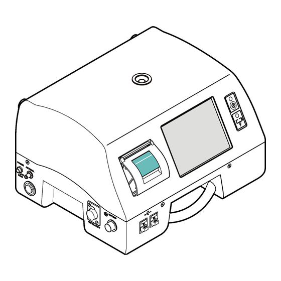
Instrument Components
Product Components
Electrical Connections
Electrostatic Discharge (ESD) Considerations
Wiring Safety Information
Back View
Front and Side View
Install the Batteries
Assemble the Particle Counter System
Install the Printer Paper
Particle Counter Assembly
Printer Paper Installation
Connect RS485 Communication (Optional)
About Network and Communications Setup
Network and Communications
Setup for Serial Communication
Setup for Ethernet Communication
Setup for Wireless Communication
Set Wireless Security
CHAPTER 5: Particle Counter Navigation
Icons - Counter Navigation Screen
Icons - General
CHAPTER 6: Configuration
About Configuration
About Basic and Advanced Operation
Set the Operation Mode at Initial Startup
Change the Operation Mode
Configure the System
Set the Time and Date
Set the Sleep Mode and Backlight Timeout
Set the Alarm Reasons Option
Set the Sample Comments Option
Alarm Reasons Options
Set the User Interface Language
Manage Units and Alarms
Manage Audible Alarm Settings
Set the Measurement Units
Set the Flow Rate Alarm Values
Add an Alarm Reason
Edit an Alarm Reason
Delete an Alarm Reason
Apply an Alarm Reason to a Data Record
Set the Inert Gas and Altitude Values
Set the Particle Count Alert (Beep Function)
Change the Relative Humidity and Temperature Probe
Manage Backup and Restore Settings
Make a Backup of Configurable Settings
Restore Settings from Backup
Configurations
Copy a Configuration
Install a Configuration
Locations, Areas and Groups
Location Management
Add a Location
Edit a Location
Configure New Settings for the Location
Copy Settings from Another Location
Set Location Alarms
Remove a Location
Change the Order of Locations
Area Management
Add a New Area
Edit an Area
Remove an Area
Change the Order of Areas
Group Management
Add a Group
Install a Group
Delete a Group
Add a Location to a Group
Sizes Function
Data Management
Store Partial Data
Manage the Data Buffer
Set the Data Buffer to Rotate Data
Set the Data Buffer Size
Real-Time PDF/CSV Option
Turn on the PDF Option
Save the Count Data to a Folder
Manage Users and Permissions
Enable the User Logon Function
Log on as Administrator
Change the Password
Replace a Forgotten Password
Add a User
Assign Groups to a User
Assign User Access Rights
Operation
Log on to the Particle Counter
Measure Particle Counts
Change the Particle Count Location
See Settings During the Particle Count
See Historical Data During the Particle Count
Use the Filter Scan Probe
Manage Sample Batch Identification
Enter or Change a Batch ID
Disable a Batch ID
Set or Clear the Batch ID
How to Use the Test and Report Wizard
About Standard Sampling Protocols
About Reports
Set up the Test and Report Wizard
Start Sample Measurement with the Wizard
Use Existing Data
Report Test Results
How to Use the Print Center
About the Print Center
Print Records Manually
Set Automatic Print Functions
Averages Report
Buffer Report (All Buffer Records)
Review Historical Buffer Data
Set the Data Filter
Clear the Data Buffer
Export Data
About Status Values in Exported Data
Sample Status Bit Mask Definitions
Configure and Enable the FTP Function
Data Transfer to the OPC Server
User-Initiated Data Upload
User-Initiated Data Download
Automatic Data Download
CHAPTER 8: Maintenance
Clean the Instrument Exterior
Set the Count to Zero
Update the Instrument Software
Charge the Batteries in the Particle Counter
Battery Recharge Intervals
Battery LED Color Indications
Suggested Battery Recharge Interval
Calibrate the Battery
CHAPTER 9: Diagnostics and Troubleshooting
Factory Settings
System Diagnostics Screen Example - Clock Battery Failure
CHAPTER 10: Parts and Accessories
Parts for the 28.3 LPM Counter (3413 and 3415)
Parts for the 50 LPM Counter (3423 and 3425)
Parts for the 100 LPM Counter (3445)
3400 Series Parts
Spare Parts Kit (2087919-01)
Related Documents
Advertisement
Quick Links
1
Instrument Specifications
Download this manual
Instruction For Use
MET ONE 3400: 3413, 3415, 3423, 3425, 3445
Air Particle Counter
DOC026.53.80202, Edition 7
12/2017
Beckman Coulter, Inc.
250 S. Kraemer Blvd.
Brea, CA 92821 U.S.A.
Table of
Contents
Previous
Page
Next
Page
1
2
3
4
5
Advertisement
Table of Contents
Need help?
Do you have a question about the MET ONE 3400 and is the answer not in the manual?
Ask a question
Questions and answers
Related Manuals for Beckman Coulter MET ONE 3400
Cash Counter Beckman Coulter MET ONE 3413 Instructions For Use Manual
Air particle counter (88 pages)
Cash Counter Beckman Coulter MET ONE 3415 Instructions For Use Manual
Air particle counter (88 pages)
Cash Counter Beckman Coulter MET ONE 3445 Instructions For Use Manual
Air particle counter (88 pages)
Cash Counter Beckman Coulter MET ONE 7000 User Manual
(32 pages)
Cash Counter Beckman Coulter MET ONE 6000 Series Manual
(298 pages)
Cash Counter Beckman Coulter HIAC 9703+ Manual
Liquid particle counter (223 pages)
Cash Counter Beckman Coulter HIAC 9703+ User Manual
Liquid particle counter (94 pages)
Cash Counter Beckman Coulter HHPC6+ User Manual
Handheld air particle counter (17 pages)
This manual is also suitable for:
Met one 3413
Met one 3415
Met one 3423
Met one 3425
Met one 3445
Table of Contents
Save PDF
Print
Rename the bookmark
Delete bookmark?
Delete from my manuals?
Login
Sign In
OR
Sign in with Facebook
Sign in with Google
Upload manual
Upload from disk
Upload from URL


Need help?
Do you have a question about the MET ONE 3400 and is the answer not in the manual?
Questions and answers