
Related Manuals for Beckman Coulter HHPC6+


Summary of Contents for Beckman Coulter HHPC6+
- Page 1 Test Equipment Depot - 800.517.8431 - 99 Washington Street Melrose, MA 02176 TestEquipmentDepot.com DOC026.97.80271 HHPC 6+, HHPC 3+, HHPC 2+ 10/2013, Edition 7 User Manual...
-
Page 2: Table Of Contents
Table of Contents Specifications on page 3 General information on page 4 User interface and navigation on page 8 Operation on page 11 Maintenance on page 17 Troubleshooting on page 18 Replacement parts and accessories on page 18 Specifications Specification Details Size range 0.3 µm - 10 µm channels per ISO 14644-1 (FS 209E) industry standard;... -
Page 3: General Information
Specification Details UI Languages English and Japanese Alarms User-selected particle channels and limits Operating environment 10 ºC to 40 ºC (50 ºF to 104 ºF) / < 95% non condensing. Pollution degree: II or better. Storage environment -10 ºC to 50 ºC (14 ºF to 122 ºF) / Up to 98% non-condensing Power requirements (internal) Internal: Rechargeable Li-Ion 7.4V 2600 mAh battery, not user-serviceable External: External Class III Power Adapter: 100-240 Vac, 50-60 Hz, 1.0A... - Page 4 Precautionary labels This is the safety alert symbol. Obey all safety messages that follow this symbol to avoid potential injury. If on the instrument, refer to the instruction manual for operation or safety information. This symbol indicates a laser device is used in the equipment. Electrical equipment marked with this symbol may not be disposed of in European public disposal systems after 12 August of 2005.
- Page 5 Class 1 laser product This instrument is classified as a Class 1 laser product. This product complies with IEC/EN 60825-1:2007 and 21 CFR 1040.10 except for deviations pursuant to Laser Notice No. 50, dated June 24, 2007. US FDA Laser Accession number 9922627-004. This product contains a non user-serviceable 760-850nm 50 mW class 3B laser.
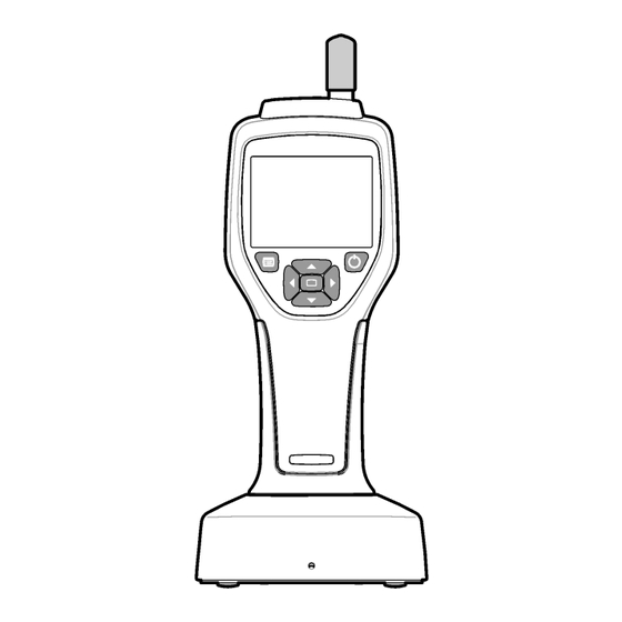
- Page 6 Figure 1 System components 1 Zero-count filter 5 Handheld instrument 2 Filter adapter 6 USB cable 3 Sample inlet protective cap 7 Cradle accessory (optional) 4 AC adapter Data and power connections Figure 2 shows the locations of the data and power connections. The ethernet port is available only on the cradle.
-
Page 7: User Interface And Navigation
Figure 2 Data and power connections 1 AC adapter connector 6 Cradle to handheld connector 2 Mini-USB port (from PC) 7 AC adapter connector 3 Cradle to handheld connector 8 USB port 4 USB port (Flash drive or memory device) 9 Ethernet port 5 Threaded tripod mount User interface and navigation... - Page 8 Figure 3 Keypad and display 1 LCD display screen 5 RIGHT arrow button 2 Menu button 6 DOWN arrow button 3 UP arrow button 7 Select button (also Start/Stop sample) 4 Power button 8 LEFT arrow button Help screens Help screens are available for some menus. Information on the help screens helps the user set up and use the instrument.
- Page 9 A sample process can be started from this screen. The process uses the stored Sample Setup values. For more information on how to set up samples and a sample process, refer to Sample setup on page 13 and Start a sample process with normal view on page 14.
-
Page 10: Operation
Table 2 Icons and functions (continued) System setup Sign on Common functions Trend data view Sample screen Buffered data view Setup functions Location setup Sample setup Alarm setup Display setup Operation W A R N I N G Fire and explosion hazards. Do not use or store the unit in direct sunlight, near a heat source or in high temperature environments such as a closed vehicle in direct sunlight. - Page 11 the Security setting, refer to the help screen in the General Setup menu and to Basic instrument setup on page 12. Start up Push the POWER button to turn on or turn off the instrument. Basic instrument setup Make sure that the battery is sufficiently charged before use. To charge the battery, refer to Charge the battery on page 17.
- Page 12 Verify instrument operation Electrical noise, sensor leakage or other interference can cause the instrument to give incorrect data. To make sure the instrument operates correctly: 1. Attach the Zero-Count Filter. 2. In the Data Display Setup screen, select the 0.3 µm channel and set the Concentration mode to COUNTS.
- Page 13 Option Description Cycles The total number of sample and hold intervals. Range: (0) to 999. When in Automatic mode, the instrument stops after the last cycle is complete. A value of 0 makes the unit run continuously until the user pushes the Select button. Mode Automatic: the instrument gets samples according to the stored parameters.
- Page 14 The trend graph screen appears. 2. Push the Select button. The Graph Setup screen appears with the Sampling Control icon active by default. 3. Do one of the tasks that follow: • Push the Select button to start the sample process with the current setup OR •...
- Page 15 Move data to a USB memory stick 1. Connect the memory stick to the USB port on the bottom of the instrument. 2. Navigate to the Buffered Data Icon and push the Select button. 3. In the Buffered Data screen, push the Left arrow until the icon that shows the USB stick and a green arrow is highlighted.
-
Page 16: Maintenance
Update instrument firmware 1. Put the update file on a USB memory stick. 2. Attach the memory stick to the USB port on the bottom of the instrument. 3. Push and hold down the menu key and push the power key. The instrument scans the USB drive for updates and installs the update. -
Page 17: Troubleshooting
Troubleshooting Diagnostics screen The Diagnostics icon is in the Communications Setup sub-menus. The Diagnostics screen shows information that may be useful in the analysis of instrument failures. Information shown includes details about instrument calibration, laser current, firmware version, battery voltage and battery charge status. Error descriptions Table 3 describes the kinds of errors that can occur.
Need help?
Do you have a question about the HHPC6+ and is the answer not in the manual?
Questions and answers