Table of Contents
Advertisement
Advertisement
Table of Contents

Subscribe to Our Youtube Channel
Related Manuals for Tecomec GEOline GEOSYsTEM 240

Summary of Contents for Tecomec GEOline GEOSYsTEM 240
- Page 2 General Information GeoSystem RevA6 1 INDEX INDEX ____________________________________________________________________________ 1 INTRODUCTION ___________________________________________________________________ 2 LEGEND __________________________________________________________________________ 3 INTENDED USE ____________________________________________________________________ 4 WARNINGS _______________________________________________________________________ 4 PACKAGE CONTENTS ______________________________________________________________ 5 DIMENSIONS ______________________________________________________________________ 6 ACCESSORIES ____________________________________________________________________ 6 TECHNICAL DATA _________________________________________________________________ 7 10 INSTALLATION OF COMPONENTS ____________________________________________________ 8 10.1 CONFIGURATIONS ____________________________________________________________ 8 10.2 CONNECTION DIAGRAM ______________________________________________________ 10 10.3 INSTALLATION ______________________________________________________________ 12...
- Page 3 General Information GeoSystem RevA6 15.4 NEW TREATMENT ___________________________________________________________ 62 15.5 TURNING ON GeoSystem _____________________________________________________ 62 15.6 TURNING OFF the GeoSystem _________________________________________________ 65 15.7 PREPARATION ______________________________________________________________ 65 15.8 AUTOMATIC OPERATION _____________________________________________________ 66 15.9 MANUAL OPERATION ________________________________________________________ 66 15.10 TANK REFILLING DURING A TREATMENT ___________________________________ 66 15.11 TOTALIZERS ____________________________________________________________ 67 15.12...
- Page 4 Dear User, Congratulations on choosing a TECOMEC S.r.l. product. TECOMEC S.r.l. is a leading company in the development and production of electronic agricultural systems. For years now, the international market has recognized our quality, experience, reliability and above all our technological innovation which results from our advanced and revolutionary know how.
-
Page 5: Intended Use
General Information GeoSystem RevA6 Please take note of the following symbols: Indicates explanatory and additional information. Maximum care is recommended. Indicates an operation that can be repeated many times, in a cycle. Indicates the standards to respect. 4 INTENDED USE A crop protection chemical spraying management system designed to work on agricultural machinery for orchard spraying and crop spraying applications. -
Page 6: Package Contents
The power supply must be protected with a 10A fuse. If it is not the case, TECOMEC S.r.l. will not be responsible for any damage to the microcomputer. Disconnect the power cable from the microcomputer when charging the vehicle battery. - Page 7 General Information GeoSystem RevA6 Description GeoSystem Monitor Power cable L=2 m Extension cable L=5 m (if available) Valve and sensor connection cable Speed sensor with cable L=5 m Dovetail bracket Foam Marker adapter cable L=0.4 m* Flowmeter adapter cable L=0.4 m GPS speed sensor* Table - Package contents...
-
Page 8: Technical Data
General Information GeoSystem RevA6 ACCESSORY DESCRIPTION Sensor to measure the flow and count the number of Magnetic Flowmeter liters Sensor to measure the flow and count the number of Paddle Flowmeter liters Pressure Sensor Sensor to measure the pressure Level Sensor Sensor to measure the liquid level in the tank Suction mount with mini VESA base Bracket to fix to a glass surface... -
Page 9: Installation Of Components
Configuration GeoSystem RevA6 INSTALLATION OF COMPONENTS 10.1 CONFIGURATIONS 10.1.1 GeoSystem Monitor - Orchard Sprayer (OS) and Crop Sprayer (CS) On the front, there are a series of switches that control the section valves of the sprayer, the main control valve and the switch to increase/decrease the flow rate/pressure. The flow rate can be adjusted manually or automatically. - Page 10 Configuration GeoSystem RevA6 Figure 3 - Crop Sprayer (CS) Monitor ON / OFF key. Series of 2-position switches (ON-OFF) for the main control valve and section valves (5 valves). One 3-position switch (ON-OFF-ON) with spring return in the OFF position for volumetric valve control Function and setting keys Alphanumeric display - 2 rows of 16 characters with backlight.
-
Page 11: Connection Diagram
Configuration GeoSystem RevA6 Figure 5 – Switch layout 1. Main valve control switch 2. Section valve control switches 3. Regulating valve control. 10.2 CONNECTION DIAGRAM 10.2.1 GeoSystem Monitor – 5-section Crop Sprayer (CS) Extension cable Figure 6 – Diagram for Crop Sprayer Version DIN43650 Connector for: JST JWPS... - Page 12 Configuration GeoSystem RevA6 Main valve Pressure sensor Foam marker (Connector: Tank level sensor FASTON) 10.2.1 GeoSystem Monitor - 2/4-section Orchard Sprayer (OS) Extension cable Figure 7 – Diagram for Orchard Sprayer Version DIN43650 Connector for: JST JWPS Connector for: 1,2,3,4,5 Section valve Flow sensor Regulating valve...
-
Page 13: Installation
Configuration GeoSystem RevA6 10.3 INSTALLATION 10.3.1 Positioning advice Figure 8 - Installation diagram for Crop Sprayer (CS) Version Figure 9 - Installation diagram for Orchard Sprayer (OS) Version Geosystem monitor Tank level sensor (optional) GPS Antenna (optional) Pressure sensor (optional) -
Page 14: Gps Antenna Installation
The monitor must not obstruct movement or limit driver visibility. 10.4 GPS ANTENNA INSTALLATION Connect the 8-pin M12 connector of the GPS antenna cable Tecomec Code #A01100002 or #A01100003 to the metallic M12 connector located at the bottom of the Geosystem monitor... -
Page 15: Speed Sensor Installation
Configuration GeoSystem RevA6 10.5 SPEED SENSOR INSTALLATION SEE DETAIL A Maintain 15 mm from other objects Front sensor Figure 11 - Speed Sensor Installation 10.5.1 Positioning advice The speed sensors must be positioned with the following precautions: Install the sensor less than 4-5 mm away from the body to be detected; Do not install the sensor body too near to other metal objects that may affect the operation of the detector. -
Page 16: Flowmeter Installation
Configuration GeoSystem RevA6 10.6 FOAM MARKER CONNECTION - CROP SPRAYER (CS) VERSION FOAM MARKER FOAM MARKER POWER SUPPLY SIDE SELECTION SX= +12 Volts when active DX= +12 Volts when active Figure 12 - Connection with the Foam Marker The Geosystem cannot directly power the foam marker because its power consumption is too high. -
Page 17: Hardware Installation Check
Configuration GeoSystem RevA6 10.8 HARDWARE INSTALLATION CHECK Before using the GeoSystem, check the correct installation of each component: • Check that the connectors are in the right sockets • Check that the cables are the correct length • Check that all screws are fully tightened •... - Page 18 Configuration GeoSystem RevA6 CONTROL, SELECTION OR MODIFICATION KEYS ON / OFF key: Turns the monitor on / off Foam marker activation key: Enables / disables the foam marker outputs on the left-hand side of the vehicle during the operating phase (active spraying) Control key: - Allows return to the previous menu - Resets the percentage increase / decrease of the spraying value...
- Page 19 Configuration GeoSystem RevA6 SWITCHES FOR THE CONTROL OF HYDRAULIC FUNCTIONS Switch for controlling the main valve: • to open the main valve, slide the switch upward (LED on) • to close the main valve, slide the switch downward (LED off) Switch for controlling the regulating valve: •...
- Page 20 Configuration GeoSystem RevA6 Then, the “Please Wait” message is shown. The operating values appear. When using a GPS antenna When you automatically switch from GPS to Proximity mode If communication with the GPS any error occurs, appear the message “GPS error” The GPS antenna is not receiving a signal .
- Page 21 Configuration GeoSystem RevA6 Press the key to modify the parameter: the choice can be modified or the value changed using the keys. If the parameter has a list of default values or names, these will be displayed by pressing the keys.
- Page 22 Configuration GeoSystem RevA6 calibration….in this example: vehicle Flowmeter calibration: This specifies how many pulses arrive at the flowmeter per unit of liquid sprayed. 1-5000 pulses/liter (Metric) or pulses/USG (gallon) (US). The value is indicated on the plate attached to the housing or by the flowmeter manufacturer.
- Page 23 Configuration GeoSystem RevA6 Minimum tank level alarm threshold: Below this value, the monitor will indicate the lack of liquid. 0-10000 liters (Metric) or USG (gal) (US). Speed measurement: Indicates the type of sensor used to measure speed: Pulse: electronic pulse input e.g. speedometer Prox: speed measured through proximity sensor e.g.
- Page 24 Configuration GeoSystem RevA6 spraying is stopped by closing the main valve. Manual speed threshold: 0-50 Km/h (metric) or mph (U.S.) Below this value, the monitor works in manual mode only. Total boom width: 0.00- 100.00 mt. Pressure calculation: Enables the pressure calculation based on the type of nozzle installed.
- Page 25 Configuration GeoSystem RevA6 sections based on the total number of the valves defined. Total width of the spray boom: This defines the width of individual sections of the sprayers. For more information see section 13.4 Number of nozzles section 1 (external): 0-200 Parameters related to the number of nozzles per section for a...
- Page 26 Configuration GeoSystem RevA6 By increasing this value, the precision is increased but the speed of variation is reduced. Maximum percentage variation of increase/decrease of the flow rate: 10, 20, 30, 40, 50% of the value set on the monitor. Adjustment response: Allows the response time of the automatic adjustment to be changed.
- Page 27 Configuration GeoSystem RevA6 value set in point 5 Minimum flow rate alarm threshold. Liquid tank specific weight: Only if the sensor level = YES, this allows the tank level to be calculated as a function of the specific weight of the liquid inside.
- Page 28 Configuration GeoSystem RevA6 Figure 16 – Bypass valve Figure 15 – Throttling valve Section valve type: ON-OFF / Metered Main Valve type: Bypass / Dump Minimum pressure: 0-200 bar If the pressure value is below the minimum for 15 seconds, an alarm is activated.
- Page 29 Configuration GeoSystem RevA6 11.3 OPERATING PARAMETER CONFIGURATION This allows all the operating parameters for each chemical treatment to be set. Turn on the monitor by pressing First message depends on the Geosystem model. The Firmware version and system name then appear. Then, the “Please Wait”...
- Page 30 Configuration GeoSystem RevA6 Keep pressing the key to pass through the subsequent programs. It is possible to delete the current selection by pressing the key. 11.3.1 LIST OF OPERATING PARAMETER MENU ITEMS Dosage setting: This sets the current value of the quantity of liquid per unit of area (liters per hectare).
- Page 31 Configuration GeoSystem RevA6 Press the key to select the ISO or USER ID. Select the nozzle using the keys.
- Page 32 Configuration GeoSystem RevA6 12 INTERFACE DESCRIPTION OF ORCHARD SPRAYER (OS) MONITOR 12.1 LIST OF KEYS AND SWITCHES AND THEIR FUNCTIONS Monitor with alphanumeric display, keys and control switches Figure 8 –OS version Monitor CONTROL, SELECTION OR MODIFICATION KEYS ON / OFF key: Turns the monitor on / off RATE key: This is used to temporarily change the value of the delivered flow.
- Page 33 Configuration GeoSystem RevA6 UP key: - Scrolls through the individual items to the previous menu - Increases the value of the parameter When modifying parameters, holding down the key allows the input values to be increased quickly DOWN key: - Scrolls through the individual items through to the next menu - Decreases the value of the parameter When modifying parameters, holding down the key allows the input values to be decreased quickly...
-
Page 34: General Parameter Configuration
Configuration GeoSystem RevA6 12.2 GENERAL PARAMETER CONFIGURATION Sets the parameters required for the proper operation of the monitor. Turn on the monitor by pressing First message depends on Geosystem model. The Firmware version and the system name: Orchard Sprayer then appear. Then, the “Please Wait”... - Page 35 Configuration GeoSystem RevA6 If the parameter has a list of default values or names, these will be displayed by pressing keys. If the input value is numeric, it will increase or decrease according to how long the key is pressed with an exponential interval. It is possible to delete the current selection or return to the previously menu by pressing the key.
- Page 36 Configuration GeoSystem RevA6 Minimum flow alarm threshold: 0-10000 l/min (Metric) or USGpm (gal/min) (US) Maximum flow alarm threshold: 0-10000 l/min (Metric) or USGpm (gal/min) (US). Speed sensor calibration: 2 modes: wheel constant = distance traveled (cm or inches) / (number of pulses per revolution * wheel speed) or Automatic over a distance of 100 meters, the pulse count is acquired.
- Page 37 Configuration GeoSystem RevA6 Simulated speed value: The monitor simulates the travel speed. 0-50 Km/h (metric) or mph (U.S.) Manual min. speed: 0-50 Km/h (metric) or mph (U.S.) Value below which, in manual mode, the spraying is stopped by closing the main valve.
- Page 38 Configuration GeoSystem RevA6 Sensitivity to change in speed: This changes the response time to the adjustment in flow rate as a function of the speed, from 1 (fast) to 5 (slow). By increasing this value, the precision is increased but the speed variation is reduced.
- Page 39 Configuration GeoSystem RevA6 Both: the system uses the flowmeter or pressure sensor to adjust the dose (l/ha). When the flow rate (l/min) falls below the value set in point 5: Minimum flow rate alarm threshold. Liquid tank specific weight: Only if the sensor level = YES, this allows the tank level to be calculated as a function of the specific weight of the liquid inside.
- Page 40 Configuration GeoSystem RevA6 Figure 19 - Bypass valve Figure 18 - Throttling valve Section valve type: ON-OFF / Metered Main Valve type: Bypass / Dump Minimum pressure: 0-200 bar If the pressure value is below the minimum for 30 seconds, an alarm is activated.
- Page 41 Configuration GeoSystem RevA6 data related to the position and the speed is unreliable. 12.3 OPERATING PARAMETER CONFIGURATION This allows all the operating parameters for each chemical treatment to be set. Turn on the monitor by pressing First message depends on Geosystem model The Firmware version and system name: Orchard Sprayer then appear.
- Page 42 Configuration GeoSystem RevA6 Press the keys to choose the type of program and confirm by pressing the key. It is possible to configure and choose up to 10 different types of program. Keep pressing again the key to pass through the subsequent programs. It is possible to delete the current selection by pressing the key.
- Page 43 Configuration GeoSystem RevA6 Row Width: Sets the row width as a function of corresponding value. Boom: Sets the boom ID. The possible values range from "A" to "J" If the "Number of Valves" parameter is equal to 4, there are 2 items relating to the Boom Type: 1.
-
Page 44: System Use
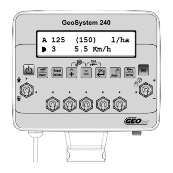
Configuration GeoSystem RevA6 13 SYSTEM USE 13.1 OPERATING CYCLE EXECUTION Based on the configured parameters, the monitor acquires the measurements from the various sensors and required adjustments. Turn on the monitor by pressing The current dosage values appear and, in brackets, the set values. The bottom line shows the speed of travel of the vehicle. - Page 45 Configuration GeoSystem RevA6 Current flow rate in liters/minute (or gallons/minute) The “@” symbol before the value indicates that the flow rate value has been calculated and not measured by the specific sensor. This happens if and only if the “Section valve type” parameter is set as “Metered”.
- Page 46 Configuration GeoSystem RevA6 Keep the key pressed for 5 seconds to set the initial tank capacity (see the Tank Capacity parameter). If the level sensor parameter is YES, the value set will be the level measured by the sensor. After the 5 seconds, the message: Completed! will appear.
-
Page 47: Calibration Procedure
Configuration GeoSystem RevA6 13.2 CALIBRATION PROCEDURE These procedures must be carried out when the treatment is not active (in manual mode and with all the switches in the OFF position). - NOZZLE CALIBRATION: This allows the characteristics of the nozzle type used to be defined (liter/minute) as a function of the pressure (bar). - Page 48 Configuration GeoSystem RevA6 Press the key again to set the Pressure and Flow Rate using the keys. Press the key to return to the previous menu. TANK LEVEL CALIBRATION Press the key to enter the tank configuration and set the calibration points.
- Page 49 Configuration GeoSystem RevA6 Definition of the second value. Repeat the operations in step 9. Perform steps 9 and 10 until the definition of all the calibration points to be set (max 25). Press the key to finish the calibration. If everything is successful, the message “Completed!”...
- Page 50 Configuration GeoSystem RevA6 BOOM CONFIGURATION Press the key in order to select the type of boom that identifies with the character from “A” to “J”. Press again the key in order to select the type of nozzle: ISO, ATR, MGA or USER Press again the key in order to select the number of nozzle in the...
- Page 51 Configuration GeoSystem RevA6 Number Speed Speed sensor 6000.0 2362.2 pulses 0.0 in/imp Calibration calibration cm/imp cm/imp in/imp per rev. * wheel speed Pressure Pressure sensor F.S. 0 bar 0 PSI 200 bar 2901 PSI Calibration calibration value Value the tank can Metric/ Tank capacity 0 USG...
- Page 52 Configuration GeoSystem RevA6 sections 1 - 5 (CS version) Number of Number of nozzles, nozzles internal section section 2 (CS) Speed Sensitivity to speed 1 fast response variation 5 slow % Max Variation Max Variation increase/decrease in 10 % 50 % flow rate Adjustment Response time of the...
- Page 53 Configuration GeoSystem RevA6 Boom type (2-3) ID of the (OS) A / B /C / D / E / F / G / H / I / J current boom ISO nozzle ISO-01 ISO-20 12 pre-configured ATR nozzle ATR-White ATR-Blue 10 pre-configured MGA nozzle MGA-White...
- Page 54 Configuration GeoSystem RevA6 13.4 SECTION WIDTH - CROP SPRAYER (CS) VERSION For the proper functioning of the GeoSystem , it is not necessary to enter the width of each section, but it is sufficient to enter the total boom width and the width of one side of the individual sections.
- Page 55 Configuration GeoSystem RevA6 13.5 BOOM SECTIONS - ORCHARD SPRAYER (OS) Section 2 Section 3 Section 1 Section 4 Picture 9 – Boom sections. Distribution with 4 sections Section 1 Section 2 Figure 10 – Boom section. Distribution with 2 sections...
- Page 56 Configuration GeoSystem RevA6 13.6 MANAGEMENT OF TREATMENTS WITH 4 SECTIONS (OS) Below is a description of the difference between an automatic adjustment with constant pressure or constant volume. 13.6.1 ADJUSTMENT IN CONSTANT PRESSURE MODE During a treatment, in the event of closure of valves of different heights between left and right, the pressure can be kept constant but the quantity of liquid per unit of area will be re-calculated based on the number and type of nozzles activated.
- Page 57 Configuration GeoSystem RevA6 13.6.2 ADJUSTMENT IN CONSTANT DISTRIBUTION MODE During a treatment, in the event of the closure of valves of different heights between left and right, it is possible to keep the volume of liquid sprayed constant but the value of pressure will be increased.
-
Page 58: Hardware Test
GeoSystem RevA6 14 HARDWARE TEST This allows a hardware test of the monitor to be carried out to check that the switches and sensor inputs are working. This test can be carried out only at start-up. Turn on the monitor by pressing After viewing the Firmware version, when the “Please Wait”... - Page 59 GeoSystem RevA6 The next value is the external counter 2 value corresponding to the speed sensor input. The next value indicates the status of the switches. 0 = OFF 1 = ON By turning on the switches, the status will change from 0 to 1 and turning them off will return the value to 0.
- Page 60 GeoSystem RevA6 Latitude (LAT) and longitude (LON) of the current position, number of satellites used to detect the position (SAT), degree of accuracy of the GPS tracking (HDOP) and the type of calculation used to detect the position (FIX). The FIX value can be 0 (no detected position), 1 (position detected by GPS) and 2 (position detected by DGPS).
- Page 61 GeoSystem RevA6 15 USE OF GEOSYSTEM 15.1 CROP SPRAYER (CS) DISPLAY Figure 26 –Crop Sprayer Display 15.2 ORCHARD SPRAYER (OS) DISPLAY Section 4 Automtic functioning...
- Page 62 GeoSystem RevA6 Figura 27 –Orchard Sprayer Display 15.3 TREATMENT DEFINITION The term treatment refers to the set of data recorded during a spraying activity. The operating parameters recorded by GeoSystem are stored in a list. The treatment list can store up to 20 treatments. The data relating to each treatment can be viewed using the appropriate keys.
- Page 63 GeoSystem RevA6 15.4 NEW TREATMENT To start the recording of data for a new treatment, select any operating cycle parameter, with the exception of the parameter: "Tank Level".” Press the key for 5 seconds. At this point, all the counters are reset. The “Tank level”...
- Page 64 GeoSystem RevA6 Disable the switch to stop the alarm. The operating values then appear on the display and, if necessary, additional information such as: • the character “M” before the current distribution value “M 125 l/ha”: this indicates that the monitor is in manual mode; •...
- Page 65 GeoSystem RevA6 CROP SPRAYER (CS) VERSION: • The symbol in the bottom left / right: this indicates that the foam marker is active. It is possible to enable this option by pressing the keys. Press again to turn off. MEMORY RESET: On start-up, press the keys at the same time to reset all the monitor parameters to...
- Page 66 GeoSystem RevA6 15.6 TURNING OFF the GeoSystem Press the key for 2 seconds in order to turn off the system. Wait for the data of the last treatment to be saved. During the turning off procedure, do not press any key and do not cut off the power, until the monitor turns off.
-
Page 67: Automatic Operation
GeoSystem RevA6 which is reset to the value set during the configuration phase. 15.8 AUTOMATIC OPERATION Automatic operation is indicated by the letter A on the left-hand side of the display. The value in brackets is the dosage set by the user; GeoSystem will control the regulating valve to keep the dosage constant as the vehicle speed varies. - Page 68 GeoSystem RevA6 keys to increase or decrease the value. 15.11 TOTALIZERS These allow the counters related to jobs to be checked. 15.11.1 READING THE TOTALIZERS Turn on the monitor by pressing Press and hold the key for 3 seconds to access the statistics from the operating mode.
- Page 69 GeoSystem RevA6 • The distance traveled (Km) • The treatment duration (hh:mm). • Average speed (km/h) • Maximum speed (km/h) 15.11.2 RESETTING THE TOTALIZERS The monitor stores the treatment data in a list of 20 elements. Press and hold the key for 5 seconds to save the most recent data stored on the list and reset all the...
-
Page 70: List Of Possible Alarms
GeoSystem RevA6 Use the keys to scroll through the list of treatments. Press the key to access the content. 16 ALARMS 16.1 WARNING AND ALARMS There are warnings and alarms to indicate specific operating faults. When an alarm goes off, a buzzer sound will be heard. Press key to disable the buzzer. - Page 71 GeoSystem RevA6 6. Low pressure alarm: The alarm is activated after 15 seconds with a pressure less than the parameter: Minimum pressure...
- Page 72 GeoSystem RevA5 17 GPS RECEIVER TEST 17.1 GPS FUNCTIONALITY TEST FOR GEOSYSTEM The GPS antenna or receiver is a device that is capable of receiving information from GPS satellites and then calculating the device's geographical position using suitable software. Time To First Fix (TTFF) is a measure of the time required for a GPS receiver to acquire satellite signals and navigation data, and calculate the correct position (called FIX).
- Page 73 GeoSystem RevA6 Switch on the Geosystem by pressing When the “Please Wait” message appears, press the keys at the same time. The Geosystem is now in hardware test mode. The Voltage value will appear and it is possible to scroll through the values using the keys.
- Page 74 GeoSystem RevA5 ROUBLESHOOTING ▪ G , FIX=0 PS CANNOT FIX POSITION Check if the GPS signal is available. Make sure that the antenna is placed in an open space far from any walls or trees. It is also recommended to switch off the computer. All hardware connections must be checked, especially the M12 connector.
-
Page 75: Troubleshooting
GeoSystem RevA6 18 TROUBLESHOOTING DISPLAY CAUSE SOLUTION There is no power. Check the power cable connections. The display does not turn on The monitor is turned off. Press the ON button. The valves are not connected. Connect the connectors The valves cannot be controlled There is no power going to the Check the electric connection A valve does not open... - Page 76 GeoSystem RevA5 19 OTHER CONFIGURATIONS - CROP SPRAYER (CS) 19.1 EXAMPLE OF GeoSystem 5W CS INSTALLATION ON 4-SECTION SPRAYING SYSTEMS Make sure the system is connected exactly as on Figure 5. In this step, the connection of the sensors is not important but the valve cable connections and the GeoSystem driver box output connection are.
- Page 77 GeoSystem RevA6 Go to the next step to verify the operation of the valves, otherwise skip to step number Set the number 5 and press the key to confirm. The new message “ General configuration Number of valves” is then displayed. Press the key to exit and to restart the monitor.
- Page 78 GeoSystem RevA5 Section 2 Section 4 Section 1 Section 3 Section 5 Figure 28 - Use of 5 sections If all the connected valves are working, enter the configuration menu again and set the valve number to 4. At this point the monitor is working with only 4 switches as shown on the Figure below:...
- Page 79 GeoSystem RevA6 Section 1 Section 2 Section 3 Section 4 Length A Length B Length B Length A Figure 29 – Use of 4 sections for CS version The links to the sections will be numbered as follows: 12Vdc battery Figure 30 - Connection for 4 sections...
- Page 80 GeoSystem RevA5 19.2 EXAMPLE OF GeoSystem 5W CS INSTALLATION ON 3-SECTION SPRAYING SYSTEMS Make sure the system is connected exactly as on Figure 5. In this step, the connection of the sensors is not important but the valve cable connections and the GeoSystem driver box output connection are.
- Page 81 GeoSystem RevA6 Go to the next step to verify the operation of the valves otherwise skip to step number Set the number 5 and press the key to confirm. The new message “ General configuration Number of valves” is then displayed. Press the key to exit and to relaunch the monitor.
- Page 82 GeoSystem RevA5 Section 2 Section 4 Section 1 Section 3 Section 5 Figure 11 - Use of 5 sections If all the connected valves are working, enter the configuration menu again and set the valve number to 3. At this point the monitor is working with only 3 switches as shown on the Figure below:...
- Page 83 GeoSystem RevA6 Section 1 Section 2 Section 3 Figure 12 - Use of 3 sections The connections to the sections will be numbered as follows: Monitor 12vdc battery Figure 29 - Connection for 3 sections...
- Page 84 GeoSystem RevA5 20 OTHER CONFIGURATIONS - ORCHARD SPRAYER (OS) 20.1 GeoSystem 4OS INSTALLATION ON 2-SECTION SPRAYING SYSTEMS Make sure the system is connected exactly as on Figure 8. In this step, the connection of the sensors is not important but the valve cable connections and the GeoSystem driver box output connection are.
- Page 85 GeoSystem RevA6 Press the key to enter the configuration. Go to the next step to verify the operation of the valves otherwise skip to step number Set the number 4 and press the key to confirm. The new message “General config. Number of valves”...
- Page 86 GeoSystem RevA5 If all the connected valves are working, enter the configuration menu again and set the valve number to 2. At this point the monitor is working with only 2 switches as shown on the Figure below: Figure 31 - Use of 2 sections NOTE: The valve outputs are associated with connector n°...
- Page 87 Rules GeoSystem RevA5 DICHIARAZIONE DI CONFORMITA’ UE EU DECLARATION OF CONFORMITY EU KONFORMITÄTSERKLÄRUNG DÉCLARATION UE DE CONFORMITÉ DECLARACION UE DE CONFORMIDAD EU ДЕКЛАРАЦИЯ О СООТВЕТСТВИИ...
- Page 88 NOTES: TECOMEC S.r.l. reserves the right to modify the contents of this manual due to hardware and software implementations for the purposes of the continuous improvement of the product and to improve the service provided to the user.
- Page 89 Rules GeoSystem RevA5 23 ISO TABLE NOZZLE TYPE [l/min] ISO-01 0.32 0.36 0.39 0.42 0.45 ISO-015 0.48 0.54 0.59 0.64 0.68 ISO-02 0.65 0.72 0.79 0.85 0.91 ISO-025 0.82 0.90 1.00 1.07 1.15 ISO-03 0.96 1.08 1.18 1.27 1.36 ISO-04 1.29 1.44 1.58...
- Page 90 Rules GeoSystem RevA5 24 ATR TABLE NOZZLE TYPE [l/min] ATR-White 0.22 0.38 0.45 0.52 0.58 ATR-Lilac 0.28 0.48 0.61 0.70 0.77 ATR-Brown 0.38 0.64 0.81 0.93 1.04 ATR-Yellow 0.57 0.97 1.25 1.44 1.61 ATR-Orange 0.77 1.32 1.69 1.94 2.16 ATR-Red 1.08 1.83 2.33...
-
Page 91: Treatment Preparation
GeoSystem RevA5 GeoSystem “QUICK REFERENCE” TREATMENT PREPARATION 1 To start the data recording for a new treatment, select any operating cycle parameter, except the “level tank” parameter. 2 The system stores the treatment data in a list of 20 elements. Press the key for 5 seconds to save the most recent data stored on the list and reset all the counters, preparing to... - Page 92 GeoSystem RevA5 CROP SPRAYER (CS) DISPLAY ORCHARD SPRAYER (OS) DISPLAY ALARMS If an alarm goes off, you will hear a buzzer. Operating Press to disable it. cycle Operating pressure The active alarm status is shown by the symbol to the right of the first line of the display. Current speed 1.
Need help?
Do you have a question about the GEOline GEOSYsTEM 240 and is the answer not in the manual?
Questions and answers