
Related Manuals for Merck Millipore CellASIC ONIX2


Summary of Contents for Merck Millipore CellASIC ONIX2
- Page 1 User Guide CellASIC ONIX2 ® Microfluidic System Cat. No. CAX2-S0000 The life science business of Merck operates as MilliporeSigma in the US and Canada. www.sigmaaldrich.com...
- Page 2 Millipore, Sigma-Aldrich, CellASIC, and Millex are trademarks of Merck KGaA, Darmstadt, Germany or its affiliates. Detailed information on trademarks is available via publicly accessible resources. © 2019 Merck KGaA, Darmstadt, Germany and/or its affiliates. All Rights Reserved. 20202092, Rev. 04/19...
-
Page 3: Table Of Contents
Contents Introduction to the CellASIC ONIX2 Microfluidic System ® ........1 1.1 Overview ...................... 1 1.2 Benefits ....................... 1 1.3 Environmental Control ..................2 1.4 Applications ....................3 1.5 CellASIC ONIX Microfluidic Plate and Cell Type Compatibility ......3 ® 1.6 Product Use Limitations .................. - Page 4 Contents (continued) Maintenance and Cleaning ..................50 9.1 Running a System Self Check .................50 9.2 Cleaning the CellASIC ONIX2 Microfluidic System ..........51 ® 9.3 Cleaning the Gasket ..................51 9.4 Gasket/Manifold Assembly ................51 9.5 Cleaning the Manifold and Tubing..............52 9.6 Replacing Manifold Luer Filters ...............54 10 Troubleshooting ....................55 11 Specifications...
-
Page 5: Onix2 Microfluidic System
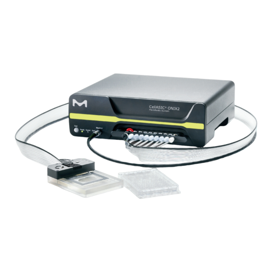
1 Intr oduction to the CellASIC ONIX2 ® Microfluidic System 1.1 Overview The CellASIC ONIX2 Microfluidic System enables continuous live-cell imaging ® with media flow, temperature control, and gas environment control. A selection of proprietary microfluidic plate designs allows cells to be captured and exposed to different conditions via flow channels. -
Page 6: Environmental Control
1.3 Environmental Control The CellASIC ONIX2 Microfluidic System can provide both temperature and ® gas environment control. If you already have or do not require temperature control, the CellASIC ONIX2 Manifold Basic can be used to provide a defined gas ®... -
Page 7: Applications
1.4 Applications The CellASIC ONIX2 Microfluidic System and Plates are perfect for many live cell ® imaging applications. The following are some common applications: ● Long-term time-lapse imaging ● Kinetic responses to solution change ● Cell cycle analysis ● Apoptosis ●... -
Page 8: Components Required
Components Required The following components are required for a functional CellASIC ONIX2 System. Refer to ® Ordering Information for additional manifolds, accessories, and other components. Component Cat. No. CellASIC ONIX2 Microfluidic System CAX2-S0000 ® Includes ONIX2 Filter Multiconnector, Software USB Drive, Replacement Filter Pack, Accessory Fittings, Self Check Plate, Cleaning Plate. -
Page 9: Symbols Used In This User Guide / Symboles Utilisés Dans Ce Manuel D'utilisation
Symbols Used in this User Guide / Symboles utilisés dans ce manuel d’utilisation The following symbols are used throughout this user guide and/or on product labels, and the user shall abide by indicated requirements: Les symboles suivants sont utilisés tout au long de ce manuel d’utilisation et/ou sur les étiquettes des produits ;... -
Page 10: Product Labeling
Product Labeling Figure 3. Product label appears on back of the system Safety Precautions / Précautions de sécurité Review and understand the safety precautions below before installing and operating the CellASIC ONIX2 Microfluidic System. ® Lire et comprendre les précautions de sécurité ci-dessous avant d’installer et de faire fonctionner le Système de microfluidique CellASIC ONIX2. - Page 11 Safety Precautions / Précautions de sécurité, continued WARNING ATTENTION Do not use with flammable or explosive Ne pas utiliser avec des liquides inflammables liquids. ou explosifs. Before cleaning and moving the system, Avant de nettoyer ou de déplacer le système, always turn off power and unplug power toujours l’éteindre et le débrancher.
-
Page 12: Installation And Setup
Installation and Setup 6.1 Packaging Inspect the packaging for damage upon receipt. If there are any signs of damage, contact the responsible shipping company. WARNING ATTENTION Do not put system components showing Ne pas mettre en marche des signs of damage into operation as this composants du système présentant des may result in severe personal injury signes de dommages, car cela pourrait... -
Page 13: Cellasic ® Onix2 Software Installation
6.3 CellASIC ONIX2 Software Installation ® In order to run this software, your computer must meet the requirements outlined below: Windows 7 or Windows 10 operating system (32- or 64-bit) ® ® 4 GB RAM or higher 1920 × 1080 resolution monitor or higher 200 MB or higher hard drive space Keyboard, mouse, USB port NOTE: Two USB ports required if using Temperature Calibration Plate (CAX2-ACT20) - Page 14 6.4 CellASIC ONIX2 Microfluidic System Setup, ® continued Figure 4. CellASIC ONIX2 Microfluidic System back panel ® 3. If gas environmental control is desired, connect one or two premixed gas tanks to the back of the system into the ports l abelled Gas A ( in Figure 4) and Gas B ( in Figure 4) using the quick-connect fittings provided (Colder Products...
- Page 15 6.4 CellASIC ONIX2 Microfluidic System Setup, ® continued NOTE: As an alternative to using premixed tanks and the on-board gas flow control, you can attach the system to a separate gas mixing source. Simply attach a gas line flowing the desired gas mixture to the white Luer fitting labeled GAS on the manifold tubing ( in Figure 6).
- Page 16 6.4 CellASIC ONIX2 Microfluidic System Setup, ® continued 6. Turn on the system power using the switch on the back panel above the power cord entry ( in Figure 4). The green Ready indicator ( in Figure 8) will light up when the unit is ready for operation.
-
Page 17: Cellasic ® Onix2 Software Features
CellASIC ONIX2 Software Features ® 7.1 Opening Screen Figure 9. Opening screen options 7.1.2 Create an Experiment Select to start a new experiment file. You will then need to select the plate type before a new experiment New Experiment file is created. Select to start new experiment based on an existing New Experiment one. -
Page 18: Manual Mode Tab
7.2 Manual Mode Tab The Manual Mode tab allows interactive operation of the ONIX2 System. Figure 10. Manual Mode tab 7.2.1 Plate View Stable and accurate flow control is achieved using air pressure above the liquid in each well. Multiple wells on a plate are grouped together and addressed by a single pneumatic line via the manifold. - Page 19 7.2 Manual Mode Tab, continued Clicking kPa will open up a conversion tool allowing conversion of psi into kPa (Figure 11). Figure 11. Psi to kPa converter tool The Dual Pressure Mode button ( in Figure 10) activates the secondary pressure for more advanced control capabilities.
- Page 20 7.2 Manual Mode Tab, continued 7.2.2 Environment Control Allows user to manually set environment control parameters Environment Control pane Temperature control can be turned On/Off and the target setpoint adjusted. Gas Flow can be turned On/Off, gas A or gas B selected, and Slow or Fast flow rate selected.
- Page 21 7.2 Manual Mode Tab, continued Clicking the Edit button next to the Run cell loading sequence, Run liquid priming sequence, or Run a custom sequence buttons opens the floating protocol editor window for the associated load cells, prime channels, or custom sequence.
-
Page 22: Plate Layout Tab
7.3 Plate Layout Tab This tab gives you the option to enter experiment information and notes. The information is recorded in the experiment file and included in generated reports. When a new experiment is created based on a previous experiment, all of the information entered on this tab (except the plate barcode number) is copied into the new experiment file. - Page 23 7.3 Plate Layout Tab, continued You can also customize the color for each well by clicking on the colored numbers across the top of the plate graphic. A color selector tool will appear; click on a color to select it. Figure 14.
-
Page 24: Protocol Editor Tab
7.4 Protocol Editor Tab The Protocol Editor allows the creation and editing of an experiment protocol. A protocol is comprised of a sequence of environment control and/or perfusion steps. Steps can be added and altered as desired. When the experiment protocol is ready, it can be executed using the Run tab. - Page 25 7.4 Protocol Editor Tab, continued 7.4.1 Step Editor Pane Each step within a protocol can be edited using the Step Editor pane, which is displayed on the right when a single step is selected. Step Description Step Editor Pane Perfusion Step A perfusion step sets the pressure and well in Figure 15)
- Page 26 7.4 Protocol Editor Tab, continued Step Description Step Editor Pane Pause When the procedure executor encounters a Pause step, it in Figure 15) halts execution and notifies the user, giving them the option to resume or abort the run. If Duration is set to zero, the pause will continue indefinitely and can be manually resumed at any...
- Page 27 7.4 Protocol Editor Tab, continued 7.4.5 Group and Repeat Steps The user can select a set of one or more consecutive steps to group them, in order to repeat that set: Select one or more steps by clicking on the step or using the shift and control keys to select multiple steps.
-
Page 28: Run Tab
7.5 Run Tab The Run tab is used to start and monitor the execution of a protocol. Figure 16. Run tab during a protocol run 7.5.1 Run data This area displays run data if the experiment has been run or is currently being run. - Page 29 7.5 Run Tab, continued 7.5.3 Dynamic Timeline Figure 17. Run tab during a protocol run The Dynamic Timeline graphically displays the protocol. If dual pressure mode is activated, two lines will be shown; otherwise there is a single timeline. The movable scroll line indicates current position in protocol.
-
Page 30: Status Bar
7.5 Run Tab, continued 7.5.4 Dynamic Timeline Mini-view Figure 18. Dynamic Timeline mini-view The mini-view is intended to be a small interface companion to your microscopy software. All other controls are the same as in the Dynamic Timeline described above. Sets the window to float on top of all other Always on Top application windows... - Page 31 7.6 Status Bar, continued Display Field Status Description Error status WARNING (flashes orange) ERROR (flashes red) If there is an error or warning, click on the ERROR/ WARNING button in the status bar to bring up the error/ warning tray for details (only in the main application).
-
Page 32: Menu Items And Advanced Features
7.7 Menu Items and Advanced Features 7.7.1 File Menu Figure 20. File menu New Experiment Select to start a new, previously undocumented experiment. A plate type selection window opens and when a plate type is chosen, a new experiment file is created. - Page 33 7.7 Menu Items and Advanced Features, continued 7.7.2 Tools Menu Figure 21. Tools menu Settings — System Tab Establishes a connection to the ONIX2 Microfluidic System. A connection to the most recently successful port is automatically attempted when the software is opened. If a connection is not automatically established, search for the serial number of your system in the Communication Port selector (the system...
- Page 34 7.7 Menu Items and Advanced Features, continued 7.7.2 Tools Menu, continued Settings — Notifications Tab Email alerts can be sent through the CellASIC ONIX2 Software to specified ® recipients when a protocol is completed or disrupted. In order to do this, an outgoing email address and mail server must be specified in notifications tab of the settings dialogue.
- Page 35 7.7 Menu Items and Advanced Features, continued 7.7.2 Tools Menu, continued Settings — Notification Tab, continued Fill out all fields in the Email Alert Settings pop-up window according to email service provider. Below are example settings for some of the most commonly used email services.
- Page 36 7.7 Menu Items and Advanced Features, continued 7.7.2 Tools Menu, continued Settings — Automation Tab The check boxes on this tab enable external control of the CellASIC ONIX2 Software, for ® more powerful integration with your microscopy software. For details on the features of the application programming interface (API), please contact Technical Service.
- Page 37 7.7 Menu Items and Advanced Features, continued 7.7.2 Tools Menu, continued Temperature Calibration, continued 1. Attach the USB cable of the CellASIC ONIX2 Temperature Calibration Plate ® (cat. no. CAX2-ACT20) to the USB port of the computer. 2. Make sure your software is connected to the ONIX2 Microfluidic System, your Manifold XT is connected to the ONIX2, and the ONIX2 Microfluidic System is ready (see Installation and Setup).
- Page 38 7.7 Menu Items and Advanced Features, continued 7.7.2 Tools Menu, continued Temperature Calibration, continued For immersion objectives and air objectives with working distance less than 2 mm: NOTE: Objective heater required! a. Seal the CellASIC ONIX2 Manifold XT to the Temperature Calibration Plate. ®...
- Page 39 7.7 Menu Items and Advanced Features, continued Unseal Plate You may use this menu item to begin a seal attempt or to unseal a plate without pushing the seal button on the system itself. 35 of 60 20202092 04/19 CellASIC ONIX2 Microfluidic System ®...
- Page 40 7.7 Menu Items and Advanced Features, continued 7.7.3 Help Menu Figure 23. Help topics User Guides Brings up an electronic copy of the system user guide or the selected plate user guide Technical Support Provides contact information About Provides version information 36 of 60 20202092 04/19 CellASIC...
-
Page 41: Operation
Operation 8.1 Before Your Experiment 8.1.1 Prepare the ONIX Plate 1. Prepare the ONIX Microfluidic Plate according to the instructions in the Plate User Guide. 2. Depending on your experiment, optional steps at this point may include: ● Precoating chambers with ECM or priming channels with growth medium ●... -
Page 42: Creating And Running A New Experiment
8.1 Before Your Experiment, continued 8.1.3 Set Up Microscope for Imaging 1. Place plate/manifold on your microscope stage. Make sure plate is flat and secure. 2. Use your microscope control software to set up a multi-position and multi-timepoint acquisition. There are many options for imaging; one typical approach is described here: ●... - Page 43 8.2 Creating and Running a New Experiment, continued 8.2.2 Run Plate Setup Sequences If cells were not loaded previously using a passive surface tension or gravity method, you may do active cell loading now. 1. Click Manual Mode to navigate to the Manual Mode tab, if not already there.
- Page 44 8.2 Creating and Running a New Experiment, continued 8.2.2 Run Plate Setup Sequences, continued 3. A protocol editor window will open. Modify the cell load sequence as desired and click OK. Figure 28. Edit cell loading sequence NOTE: Plate Setup sequences are saved as part of your experiment file.
- Page 45 8.2 Creating and Running a New Experiment, continued 8.2.3 Enter Experiment Information 1. Click Plate Layout to go to Plate Layout tab. 2. [Optional] Enter your experiment setup: contents of wells, text description of experiment, and plate barcode. 3. Modify colors assigned to well groups, if desired, by clicking on colored number labels.
- Page 46 8.2 Creating and Running a New Experiment, continued 8.2.4 Create the Protocol 1. Click Protocol Editor to go to the Protocol Editor tab. Figure 31. Protocol editor 2. Add and modify perfusion, pause, temperature set, and gas set steps as desired.
- Page 47 8.2 Creating and Running a New Experiment, continued 8.2.5 Run the Experiment 1. Click Run ( in Figure 31) to go to the Run tab. 2. Click Start Run to open the final Pre-run Check dialogue. If the experiment needs to be saved, or if there are errors or warnings you will be notified here.
- Page 48 8.2 Creating and Running a New Experiment, continued 8.2.5 Run the Experiment, continued Figure 33. Experiment will pause if an error occurs during a run NOTE: If a warning condition occurs, e.g., gas supply low, it will be recorded in the experiment data. If an error condition occurs, e.g., the seal to plate is lost during execution of a protocol, the experiment will pause and the event will be recorded in the experiment data.
-
Page 49: Repeating A Previous Experiment With Minimal Clicks
8.3 Repeating a Previous Experiment with Minimal Clicks 8.3.1 Create Experiment File Based on a Previous Experiment 1. Click New experiment based on previous on the opening screen or File menu. 2. In the file browser find your previous experiment and click Open. 8.3.2 Run Plate Setup Sequences 1. -
Page 50: Using The Mini-View
8.4 Using the Mini-view 8.4.1 Begin Experiment 1. Launch application. 2. Click New Experiment on opening screen. 3. In the Select Plate Type dialogue, select the desired plate type (e.g., M04S-03 - Plate for Mammalian Cells) and click OK. 8.4.2 Open Plate Mini-view 1. - Page 51 8.4 Using the Mini-view, continued 8.4.3 Operate the ONIX2 Manually 1. If desired, click Dual Pressure Mode ( in Figure 36) to activate secondary pressure. 2. Set pressures X and Y ( in Figure 37). 3. Click on Well groups and Pressure Select buttons to activate flows.
-
Page 52: Viewing And Exporting Data From A Previously Run Experiment
8.5 Viewing and Exporting Data from a Previously Run Experiment 8.5.1 Open Experiment File 1. Click Open Previous Experiment on opening screen. 2. In the file browser find your previous experiment and click Open. 8.5.2 View Run Data 3. Click Run to go to the Run Tab. 4. - Page 53 8.5 Viewing and Exporting Data from a Previously Run Experiment, continued 8.5.3 Export Data 1. Click Export to export the collected run data in TSV (tab-separated value) text format. The file can be opened using standard spreadsheet applications. 2. In file browser, select file name and location. 3.
-
Page 54: Maintenance And Cleaning
Maintenance and Cleaning WARNING ATTENTION Perform only the maintenance procedures Ne réaliser que les opérations de maintenance described in this manual and observe the décrites dans ce manuel et prendre les précautions relevant safety precautions. Failure to de sécurité adéquates. Le non-respect de ces do so may cause property damage or exigences peut provoquer des dommages personal injury. -
Page 55: Cleaning The Cellasic ® Onix2 Microfluidic System
9.2 Cleaning the CellASIC ONIX2 Microfluidic System ® Wipe dust off outer surface of system enclosure. Do not allow liquid to enter the system while cleaning. 9.3 Cleaning the Gasket Remove the gasket from manifold periodically and clean gently with soap and water. Rinse with distilled water and/or 70% ethanol and shake off excess liquid. -
Page 56: Cleaning The Manifold And Tubing
9.5 Cleaning the Manifold and Tubing The glass on the top of the CellASIC ONIX2 Manifold XT and Manifold Basic can be ® gently cleaned with 70% ethanol or a glass cleaner. NOTE: Manifold components are not autoclavable. If fluid enters the manifold tubing during the course of an experiment, it should be cleaned as described below, and the filters should be replaced. - Page 57 9.1 Cleaning the Manifold and Tubing, continued Figure 43. Cleaning sequence interface 5. When cleaning sequence is complete, click Dry to expel the remaining liquid in the lines. 6. Cleaning and drying sequences can be repeated until manifold and tubing are acceptable.
-
Page 58: Replacing Manifold Luer Filters
9.6 Replacing Manifold Luer Filters If the Luer filter fittings become wet and/or contaminated, they can be replaced easily. First remove the CellASIC ONIX2 Filter Multiconnector from the front panel, ® then twist the lock collars counterclockwise to eject the filters. Attach new filters by placing them loosely on male Luer fittings inside the lock collar. -
Page 59: Troubleshooting
Troubleshooting General Observation Potential Cause Recommended Action 1. System does not No AC power Confirm that the power cable is securely power on connected to the system and the power outlet. Verify that the outlet has power. Make sure the ON/OFF switch on the rear panel is in the ON position. - Page 60 Software Issues Observation Potential Cause Recommended Action 1. Email Alert not Connection to server failed Check information entered, internet working connection, and firewall settings. Email placed in junk folder Confirm that sender address is not blocked by recipient email. Errors (may appear in status bar and error/warning tray) Error Potential Cause...
- Page 61 Warnings (may appear in status bar and error/warning tray) Warning Potential Cause Recommended Action 1. Gas A/B low Gas cylinder supply getting low Replace the gas cylinder. 2. Gas A/B Gas cylinder empty or not Reconnect or replace the gas cylinder. empty or not connected Make sure gas cylinder is connected to...
-
Page 62: Specifications
Specifications General Dimensions 330 mm wide × 306 mm deep × 108 mm high (13 in. × 12 in. × 4.25 in.) Weight 6.7 kg (14.75 lb) Power consumption 100–240 VAC, 50/60 Hz, 40 W Cooling mode Air cooled (natural convection) Environmental conditions For indoor laboratory use Operating temperature... - Page 63 Temperature Control (Requires CAX2-MXT20 CellASIC ONIX2 Manifold XT) ® Temperature control Room temperature to 40 °C range Control method Bi-directional PID ± 1 °C (using the CAX2-ACT20 ONIX2 Temperature Calibration Plate Accuracy of sample can result in accuracy as high as ± 0.2 °C) chamber temperature ±...
-
Page 64: Ordering Information
Ordering Information Purchase these products online at www.sigmaaldrich.com/products. Product Description Qty/Pk Cat. No. CellASIC ONIX2 Microfluidic System CAX2-S0000 ® (includes ONIX2 Filter Multiconnector, Software USB Drive, Replacement Filter Pack, Accessory Fittings, Self Check Plate, Cleaning Plate) CellASIC ONIX2 Manifold XT (Temperature Controlled) CAX2-MXT20 ®...
Need help?
Do you have a question about the Millipore CellASIC ONIX2 and is the answer not in the manual?
Questions and answers