Table of Contents
Advertisement
Quick Links
Advertisement
Table of Contents

Subscribe to Our Youtube Channel
Related Manuals for Merck APC SmartTouch


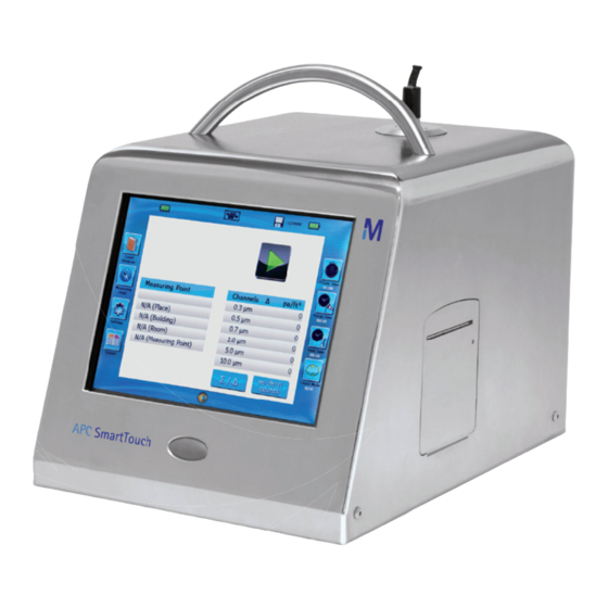
Summary of Contents for Merck APC SmartTouch
- Page 1 APC SmartTouch Airborne Particle Counter Operation Manual Version 2.0...
- Page 2 Produced by Merck KGaA Frankfurter Strasse 250 64293 Darmstadt Germany MANUAL HISTORY The following is a manual history of the APC SmartTouch Revision Date: April 2012 IMPORTANT NOTE In the following Merck shall mean Merck KGaA, Darmstadt, Germany.
-
Page 3: Table Of Contents
Contents Report Range Selection Safety Information Report Type Selection Range I. Symbols FS 209 (range) Safety ISO 14644 (range) Laser safety GMP (range) Labels Average/Min/Max (range) Description of Caution/Warning symbols Printing reports Caution or warning symbols Report place, building or room Important information Report type selection locations II. -
Page 4: Safety Information
(internal) rized technician. Laser safety 5. European symbol for non-dispos- • The APC SmartTouch Airborne Particle Counter is a Class I la- able item. Item ser-based instrument. must be recycled. • During normal operation, you will not be exposed to laser radi- ation. -
Page 5: Description Of Caution/Warning Symbols
IMPORTANT Caution or warning symbols Do not use the APC SmartTouch in hazardous areas, Eex areas, where a fi re and/or explosion may occur. The following symbols may accompany cautions and warnings to indicate the nature and consequences of hazards:... -
Page 6: Introduction And Unpacking
9921: 1997 and ISO 21501 standard. Delivery check Carefully unpack the APC SmartTouch from the shipping container and verify that all the items (see pictures) listed in the following table are present. Contact your local Merck representative immediately if items are missing or broken. - Page 7 APC SmartTouch 1 CFM 1.44181.0001 APC SmartTouch 50 LPM 1.44182.0001 APC SmartTouch 100 LPM 1.44183.0001 APC SmartTouch 1 CFM & 100 LPM 1.44093.0001 Stainless Steel Isokinetic Probe 1 CFM 1.44084.0001 Stainless Steel Isokinetic Probe 50 LPM 1.44121.0001 Stainless Steel Isokinetic Probe 100 LPM 1.44119.0001...
-
Page 8: Optional Accessories
(not shown) Compressed Gas Adapter (CGA) 1.44179.0001 Sampling Tubing (per meter) 1.44104.0001 Purge Filter 942 841 APC SmartTouch Download Utility Software CD 1.44077.0001 (not shown) USB Cable 1.44100.0001 Nozzle Set Compressed Gas Adapter, 1 CM 1.44170.0001 Nozzle Set Compressed Gas Adapter, 50 LM 1.4168.0001... -
Page 9: Getting Started
Getting Started This chapter provides information to help you use the APC SmartTouch including: • rear panel • connection ports • providing power/charging the batteries • switching on the instrument • working with settings • performing a zero count check • installation of the Isokinetic probe • Running a basic sample Rear panel This is the rear panel of the instrument. -
Page 10: Power Supply Connection
Power supply connection Please charge the instrument for 4 hours before using for the first time. Insert power plug as shown After this initial 4 hour charge the instrument can either be used via the external power supply or the internal rechargeable lithium ion batteries. NOTes: When the instrument is connected to a power source the batteries will be charged even when the counter is not switched on. -
Page 11: Battery Indicator
Battery indicator Then this screen will appear. These symbols indicate the battery charge When these symbols turn red the instrument should be used reconnected with the external power supply. The instrument can be used as normal during the recharge cycle. setting the screen contrast Press Here Press here or here to Increase or decrease... -
Page 12: Settings
settings In settings all the basic parameters such as date and time and language can be set. By touching the settings icon you will get the following screen. To Access the current status of the instrument press here. -
Page 13: Status Screen
status screen This screen is showing the actual firmware version of the counter and also the calibration date, end of calibration date (calibration is valid for 12 months), pump duration time, laser current, storage battery, customer reference, serial number, MCA number (for internal use). To return to the Settings Menu press here This Screen re-appears. -
Page 14: Language Selection
Language selection Select your language by pressing next to your countries flag then press OK. Please note you need to fully press the OK button twice for the new language to take effect. Time format To set the time format select time from the settings menu, this screen will appear. -
Page 15: Setting The Date
setting the date Now press the date key This screen will appear. setting date format Select the required date format then press date to change the date. The buttons above and below are used to increase or decrease the date. When correct press OK. -
Page 16: Setting Date And Time Using The Screen Keyboard
setting date and time using the screen keyboard To access this feature in both modes (time/date). Touch the screen here and then this virtual keyboard will appear. You can also use this virtual keyboard to set the date and time. When finished press OK. -
Page 17: Setting Instrument Name
setting instrument name You can give the instrument a unique number or name if required. From the system menu select Instrument Name. This screen will appear. Type in the Name required and press OK. Calibration lock It is possible to lock the instrument so it cannot be used if the calibration has expired. -
Page 18: Calibration Alarm
Calibration alarm You can also set an alarm to be displayed when the cali- bration is out of date. From the system menu screen select Alarm for Calibration date and this screen will appear. By pressing here you can switch the Alarm on and the screen will change to this. -
Page 19: Selecting Flow Rate (Dual Flow Only)
(Dual flow only) This is only available for dual flow rate APC SmartTouch instruments. You will get the following screen. You can select between a 1 ft3 and a 100 LPM flow rate. Select the required flow rate and the instrument will return to the main screen. -
Page 20: Lan (Local Area Network) Connections Ip Address
LAN (Local Area Network) connections IP address It is possible to connect the instrument to a LAN Network, this requires an Instrument IP address, to set this address follow the next screens. NOTe: We would recommend the use of the fully automatic feature built into this Instrument unless you are fully trained in setting this type of address. -
Page 21: Automatic Method
Automatic method Now Press Here Now Press Here Now Press Here You are now connected to a LAN-Network... -
Page 22: Manual Method
Manual method If you are fully trained in how to set this type of address please follow these steps. Press Here Type in the required IP Address. Then press OK. You need to repeat this process for the sub-mask address now press here. - Page 23 Type in the required IP Address and then press OK. Now Press Here You are now connected to a LAN-Network.
- Page 24 NOTe: Switch off your wireless connection before you proceed with the following steps! A direct link means that the APC SmartTouch will be connected directly with a network cable to a PC. Click on the Start Icon on your desktop...
- Page 25 This window will appear Click on features, the following screen appears: Double click on Internet protocol (TCP/IP) the following screen appears:...
- Page 26 APC Download Utility Software. UsB Connection For direct connection between a single computer and the APC SmartTouch we recommend the use of a USB connec- tion. Plug the USB cable into the APC SmartTouch and into a USB port of the computer then start the APC Download Utility software pear.
- Page 27 The Connected Instrument will appear here (if you have more than one instrument connected to the network they will all appear in this box). Now click on the instrument you want to connect too Now Click here to connect to the highlighted instrument This is the same screen after connection.
-
Page 28: Installing And Using Zero Count Filter
Installing And Using Zero Count Filter Zero Count Filter This is the Zero Count Filter This is the protective cover It is important to the correct operation of the Zero Count Filter that the tube is kept as short as possible and never over 100 mm. Only the correct tube should be used. -
Page 29: Remove Protective Cover From Zero Count Filter
Remove protective cover from Zero Count Filter Pull off to remove the protective cover Retain protective cover for future use Fitting Zero Count Filter to instrument Ensure a good air tight fit between these parts for correct operation Ensure this tube is as short as possible and the filter stands vertical. -
Page 30: Purge System
After the Zero Count Filter has been installed it is very important to clean (purge) the system before reading the values to qualify the system. Purge system Press “Purge Time” to define the initial wait time and the purge time. “Initial wait time”... - Page 31 This screen will now appear. Touch the screen here until the screen changes This screen will now appear. Increase Hours Increase Minutes Increase Seconds Decrease Hours Decrease Minutes Decrease Seconds To set the desired time touch the up or down points intern until the desired time is set.
-
Page 32: Setting Purge Wait Timer
This screen will reappear setting Purge Wait Timer The hold time defines how long the sampling stops between samples. This value is only relevant if “Count Cycle Mode” or “Auto Mode” is activated. Now touch the screen here. This screen will now appear. Increase Hours Increase Minutes Increase Seconds Decrease Hours... - Page 33 This screen will reappear. Now touch the screen here. This screen will reappear. NOTe The time you have just set will be displayed here. You have now successfully set the purge timer. Next you need to set the count timer.
-
Page 34: Setting Count Timer
setting Count Timer This is the Count Timer Touch the screen here until the Icon changes color The screen will look like this briefly. This screen will now appear. You can either select “Time” or “Volume”. -
Page 35: Setting Timer
setting Timer Touch here to set the timer in time mode. This screen will appear. Increase Hours Increase Minutes Increase Seconds Decrease Hours Decrease Minutes Decrease Seconds Once you have set the desired time touch here... - Page 36 This screen will reappear. Now touch the screen here. This screen will reappear. NOTe The time you have just set will be displayed here. NOTe If you want to use the Volume function follow the next steps instead of setting the count timer, if you do not want to use the volume function go to next section Starting Purge Cycle.
- Page 37 This screen will appear. To Increase volume touch here. To decrease volume touch here. Once you have set the volume touch here You have now successfully set the count timer or the volume next.
-
Page 38: Starting Purge Cycle
starting Purge Cycle Now touch the screen here. This screen will now appear and the motor will start (the laser is not active). To stop the purge cycle touch the screen here. The Timer will count down here. After the purge time you set has elapsed the count timer will automatically switch on and this screen will appear. - Page 39 After the purge cycle has completed This screen will appear and all channels should read “0”. NOTe If this is not the case please repeat twice, if the counts are still not zero please contact the Merck organisation.
-
Page 40: Removal Of Zero Count Filter
(1) particle counted at any size in five 5 minutes. NOTe: If the instrument does not go to zero (one (1) particle in 5 minutes is considered zero), run a extended purge cycle as described above if the instrument still not give a zero count please contact Merck. -
Page 41: Installing And Using The Isokinetic Probe
Installing and Using the Isokinetic Probe 100 Litre isokinetic probe Connection tube Tripod connection point NOTe It is important to remember only the tube supplied should be used with this instrument. If a tube length of over 1 meter is required we would advise the instrument is recalibrated with the required length of tube. - Page 42 Now fit the correct isokinetic probe by pushing down. Ensure a good air tight fit between these parts for correct operation. You are now ready to take your first sample. NOTe There is a pre-programmed sample cycle that can be used at this point, to use it follow the following instructions.
-
Page 43: Pre-Programmed Sample
Pre-programmed sample From the main screen. Now touch this icon (Measuring Point). This screen will briefly appear. Now this screen will appear. To use the pre-programmed recipe for a 100 litre instrument touch the screen here. - Page 44 This screen will appear. Now touch the screen here. Now touch the screen here. This screen will appear. Now touch the screen here. The pre-programmed sample will now start. This screen will appear and the motor will start.
- Page 45 After the short purge time the screen will change to this. This symbol indicates the laser is now on. You can now see counts on each of the channels After the pre-programmed time the laser symbol will disappear and the instrument motor will switch off. This is the result per channel.
-
Page 46: Result Reports
Result reports Now press here and this screen will appear. To select the report type press here. Now select either “Cleanroom” (data stored for named Cleanrooms) or “Memory”. -
Page 47: Report Range Selection
We will now presume you have selected cleanroom. This screen will appear. On this screen you can either select a range of results based on date and time or by a place, building, or room. We will assume you select by date and time first. Report Range selection Press here to start to select the range. -
Page 48: Report Type Selection Range
Now press here to select the last record you want to see. Now press OK. Report Type selection Range You can now select the type of report you need for your records. Each report is configured to meet the requirements of the regulations. -
Page 49: Iso 14644 (Range)
IsO 14644 (range) GMP (range) Average/Min/Max (range) -
Page 50: Printing Reports
Printing reports This is the same for all the report types. The built in printer will now start and the selected report will be printed. Press here. Report place, building or room Now Press one of the 3 selection types (you must start with Place). - Page 51 Select the place you require from the list and then press OK. You must now select the building. Select the building you require then press OK (you must select building before room).
-
Page 52: Report Type Selection Locations
Now select the room you want from the list. Now press OK. Report type selection locations You can now select the type of report you need for your records. Each report is configured to meet the requirements of the regulations. The following screens show examples of each type. -
Page 53: Iso 14644 (Location)
IsO 14644 (Location) GMP (Location) Average/Min/Max (Location) As before all record types can be printed. Please see printing reports. -
Page 54: Memory
Memory You can also choose to select the records by a record number, to do this select Memory (press Here). Press here and the Virtual Keyboard will appear. Enter the number you want to start the report for then press OK. -
Page 55: Report Type Selection Memory
Press here and the Virtual Keyboard will appear. Enter the highest number you would like to see, then press OK. You will now be taken to the report type screen Report Type selection Memory You can now select the type of report you need for your records. -
Page 56: Fs 209 (Memory)
The following screens show examples of each type. Fs 209 (Memory) IsO 14644 (Memory) GMP (Memory) -
Page 57: Average/Min/Max (Memory)
Average/Min/Max (memory) As before all record types can be printed please see printing reports. -
Page 58: Clear Records
Clear records The following screens explain how to clear records from the instrument. Press Here You will then get this screen, Press Yes to clear all records. You must confirm this action by pressing OK. After you press OK all records will be deleted. -
Page 59: Count Mode
Count Mode There are six different count modes to perform the sam- pling. By touching count mode you will get the following screen. Count Mode Select the type of count mode you require by pressing on it. This Symbol will alter to your selection... -
Page 60: Setting Concentration/Counts
setting concentration/counts There are four modes to present the count results of the particle channels: counts per m3, counts per ft3, counts per liter and total counts. Press here This area will show the selected Concentration Press on the type of concentration you require. -
Page 61: Selecting Differential Or Cumulative
selecting differential or cumulative The count results per particle size channel can be presented in the cumulative or differential mode. This Area will show the mode selected. Press here to toggle between the 2 modes. Recipe All the settings that have been used up to now can also be accessed via the recipe screens. -
Page 62: Setting Channels
setting channels In channel settings it is possible to change the particle size of the channel in increments of 0,1 µm. For example the 0,3 µm channel can be set into 0,4 µm. Touch a channel and you will get the following screen. To Change the Particle detection size press here NOTe... - Page 63 Touch size and you will get the following screen to change the size of the particle of a certain channel. Change the particle size of channels by using the arrows and press OK. Press here to access the numeric pad using the Key pad enter the size you require and press OK.
-
Page 64: Setting Channel Alarms
setting channel alarms In this screen you can set the alarm limit to a desired level of particles. An alarm (audible and visible, the channel that generated the alarm will be highlighted in orange) will occur when the level has been passed. Change the particle size of channels by using the arrows... -
Page 65: Action Limits
Action Limits To set the action limit to a desired limit. Press here To Set the Action Limit use these keys then press OK This alarm level should be used as an action alarm and should be interpreted in a way that action (like a produc- tion stop) needs to be taken in the measurement area. -
Page 66: Alarm Tone
Alarm tone To switch the audible alarm on or off press here Printer To set the printer activity (on/off) Press here Press Here to switch ON or Off Then press OK... -
Page 67: New Measurement Point
The measuring point is described by 4 levels: place, build- ing, room and measuring point. As used with HACCP. Measuring points can be uploaded by using the APC SmartTouch Download Utility Software. Detailed Press here instructions can be found in the Software Manual. - Page 68 Press here Press here. Then Press OK Press here...
- Page 69 Press here. Then Press OK Press here Press here. Then Press OK...
- Page 70 Now press here Now type in the required name then press OK. You can now enter new names by repeating the last 2 screens only. Full new measurement points including place, building; room and measurement points can be created and downloaded to the instrument using the PC Software.
-
Page 71: Usb Interface
UsB interface When a USB stick is inserted this Icon will appear UsB stick icon To Use the USB interface press here Import/export via UsB Press either “Import” or “Export” and then OK. -
Page 72: Export Data
export data If you have chosen export this screen will appear, the default is all fields to be ticked for export to deselect a field press on it. When you have selected the data you do not want to export press on OK the data with the tick next to it will now be exported to the USB Port. -
Page 73: Import Data
Import data If there is no data to import the screen will look like this. The default is all fields to be ticked for export to deselect a field press on it. In the same way you need to select the data to import from the list then press OK to import the required data. -
Page 74: User
User If you are using the Instrument with the PC software you will be able to select a user. After you have downloaded the data from the PC Soft- ware, the next time you switch on you will be prompted for a User and Password. - Page 75 Now type in the password for the user name that you have selected. This password is case sensitive. When you have finished press OK.
-
Page 76: Compressed Gas Adapter (Cga)
The Compressed Gas Adapter (CGA) is an accessory used with the APC ErgoTouch Pro 2, APC Handheld, APC Portable, APC M3 and APC SmartTouch Airborne Particle Counters to monitor the particulate content of compressed gasses. It is routinely used in areas where specified particle counts must not be exceeded due to legal requirements or individual standards. -
Page 77: Selection Of The Orifice
NOTe: The correct orifice must be selected for the input pressure and output flow rate, or the particle count accuracy will be affected. The CGA may be mounted to a wall using the included bracket, or it may simply be connected to the pressure line if the line can support the weight. -
Page 78: Wall Mount
The appropriate thread sealer depends on the application. Where possible, Teflon Tape is recommended to seal the threads. Teflon Tape is inexpensive and widely available. You may also use whatever thread sealer is used in your facility’s cleanroom. To connect the proper orifice to your CGA: 1. - Page 79 WARNING: Dangerous gasses such as Oxygen and toxic gasses should not be sampled using the CGA. If the CGA will be used with gasses other than air or Nitrogen please contact Merck for more information. CONNeCTING the VeNT PORT The vent port provides a path to exhaust the excess gas from the CGA. There are three commonly used procedures for venting the excess gas coming from the CGA.
-
Page 80: Maintenance
Maintenance Daily cleaning of your CGA is not necessary unless it is stored or used in an uncontrolled environment, the gas line was highly con- taminated, or your particle counts are unexplainably high. Since the device is made of stainless steel it does not generate particles but it can harbor contaminants from other sources. -
Page 81: Cga Technical Specifications
CGA Technical Specifications The APC Compressed Gas Adapter can be used with all instruments, the APC SmartTouch, M3 and other Portable Airborne Particle Counters. Sample Gas Pressure Range 10-150 PSIG Sample Flow Rate 0.1 and 1.0 CFM, 50, 75 and 100 LPM... -
Page 82: Adding New Printer Paper
Adding New Printer Paper 1. Turn off the power on the APC SmartTouch. The printer is located on the right side of the instrument. Open the printer door by pressing a stylus in the hole of the printer door. Press until the door opens. -
Page 83: Maintenance
There are no user-serviceable parts inside this instrument. Opening the instrument case may void the warranty. Merck recom- mends that you return the APC SmartTouch Airborne Particle Counter to your authorized service center for any required maintenance or service not described in this manual. -
Page 84: Troubleshooting
Merck technical support Temperature Humidity • Temperature/RH probe was not recognized • Detach and reconnect probe. If problem Probe Error persists, contact Merck technical support Flow Error • Instrument was unable to control flow rate • Restart measurement The flow error is indicated... -
Page 85: Contacting Customer Service
Before returning your APC smartTouch please check the trouble shooting guide. Returning the APC smartTouch Airborne Particle Counter for service First contact your local Merck representative to make arrangements. If you don’t know or don’t have a Merck representative, you can contact Merck directly: Visit our website at http://www.your-contacts/biomonitoring.com,... -
Page 86: Appendix A Specifications
0°C to 50°C; Up to 98% non-condensing relative humidity IP Protection IP20 Included Accessories Power supply, power cord, two (2) batteries, isokinetic probe, purge filter, APC SmartTouch Utility software, user manual on CD, USB computer cable, calibration certificate, and Quick Start Guide. - Page 88 Existing laws and regulations are to be observed in all cases by our customers. This also applies in respect to any rights of third parties. Our information and advice do not relieve our customers of their own responsibility for checking the suitability of our products for the envisaged purpose. The M mark is a trademark of Merck KGaA, Darmstadt, Germany. Contact: www.your-contacts.com/biomonitoring...
Need help?
Do you have a question about the APC SmartTouch and is the answer not in the manual?
Questions and answers