
Related Manuals for Merck Supelco TLC Explorer


Summary of Contents for Merck Supelco TLC Explorer
- Page 1 TLC Explorer Documentation System 1.52610.0001 Operational User Manual Version 2023/11...
-
Page 2: Table Of Contents
Content 1 Introduction ......................6 Intended Use of TLC Explorer ................6 Safety and Handling Instructions ................6 1.2.1 Do NOT Operate the TLC Explorer if … ............7 1.2.2 Installation Requirements ................8 1.2.3 Ultraviolet Radiation Exposure ..............8 1.2.4 General Notes on Handling ................ - Page 3 Content Content 4 Operational Guide..................... 26 6 Backup and Data Migration ..................57 4.1 Typical Workflow ....................26 Generating a Backup ...................57 4.1.1 Main Menu ....................28 Recovering Backup ....................58 6.3 Migrating User Data to a different TLC Explorer ............58 Device Preparation ....................28 Visual Inspection ....................29 7 Software Updates ..................... 59 Image Capture ....................29 Current Software Version ..................59 Loading an Existing Image Set ................32...
-
Page 4: Introduction
1 Introduction - 1.2 Safety and Handling Instructions 1 Introduction Intended Use of TLC Explorer 1.2.1 Do NOT Operate the TLC Explorer if … The TLC Explorer is designed to document and evaluate thin-layer chromatographic plates. It Before connecting the TLC Explorer to a power supply, ensure none of the following applies: offers a safe, fast and flexible way to visually inspect and digitally record images of TLC plates •... -
Page 5: Installation Requirements
1 Introduction - 1.2 Safety and Handling Instructions 1 Introduction - 1.2 Safety and Handling Instructions 1.2.2 Installation Requirements 1.2.4 General Notes on Handling For a safe and reliable operation, please follow the following guidelines when setting up the de- •... -
Page 6: A Short Introduction To Tlc
1 Introduction - 1.3 A Short Introduction to TLC 1 Introduction - 1.3 A Short Introduction to TLC - 1.4 About this Manual A Short Introduction to TLC 1.3.2 Retardation Factor R Thin-layer chromatography (TLC) is a fast, easy-to-use, and highly versatile separation technique is defined as the distance travelled by an individual component divided by the total distance for qualitative and quantitative analysis. It is ideal for rapid identification, screening, and reac- travelled by the solvent;... -
Page 7: Get To Know Your Tlc Explorer
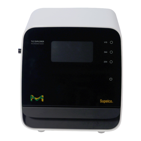
2 Get to Know Your TLC Explorer - 2.1 TLC Explorer Front 2 Get to Know Your TLC Explorer TLC Explorer Front 2.1.2 F2, F3, F4 - Illumination Buttons and Indicators Placing your finger on the circle to the right of the button labels ‘Vis’, ‘366’ and ‘254’ switches the respective illumination on or off. Only one of these light sources can be active at a time. A light under the circle indicates an illumination is switched on – be it manually by the user after press- ing the button or controlled by the software to capture images. -
Page 8: Tlc Explorer Back
2 Get to Know Your TLC Explorer - 2.2 TLC Explorer Back 2 Get to Know Your TLC Explorer - 2.2 TLC Explorer Back TLC Explorer Back 2.2.4 B5 - WiFi Antenna Connector Each TLC Explorer is shipped with a separate WiFi antenna A1. In order to connect the antenna to the device, straighten up the joint at the antenna’s base and screw it clockwise on the RP-SMA connector on the back’s top left side. -
Page 9: Tlc Explorer Baseplate
2 Get to Know Your TLC Explorer - 2.3 TLC Explorer Baseplate 2 Get to Know Your TLC Explorer - 2.4 Accessories TLC Explorer Baseplate Accessories 2.4.1 A1 - WiFi Antenna To provide a reliable WiFi connection, the TLC Explorer comes with an external antenna A1, which needs to be mounted on the connector (see section 2.2.4 for details). -
Page 10: A4 - Power Bank
2 Get to Know Your TLC Explorer - 2.4 Accessories 3 First Use 2.4.3 A4 - Power Bank Unpacking and Scope of Delivery Your TLC Explorer is built and inspected according to the relevant guidelines and norms for elec- tronic instruments (for details see section 12). It left the factory in a safety-tested and technical- ly perfect condition. -
Page 11: Setting Up For Safe Operation
3 First Use - 3.2 Setting Up for Safe Operation - 3.3 Powering Up and a `First Look´on Your Plate 3 First Use - 3.4 Connecting Your Laptop Setting Up for Safe Operation Connecting Your Laptop Please carefully read section 1.2.2 about installation requirements before selecting a suitable There are different ways to connect various types of user devices (laptops, desktop computer, location for your device. -
Page 12: Creating A First User
3 First Use - 3.4 Connecting Your Laptop 3 First Use - 3.5 Creating a First User Creating a First User You should see a welcome screen similar to the following (see figure 3.3): Begin personalizing your TLC Explorer by selecting a language and entering a first username. Since usernames are internally used to name files and directories, not all special characters or symbols are allowed. In case you entered an invalid character, the line under the field will turn red and a warning message will appear underneath. The full name, which you can enter in the next field, is less restrictive and optional. It may be used to identify the user e. g. as the author of reports. Figure 3.3: First opening of TLC Explorer user interface Setting a bookmark and/or selecting the menu point ‘Add to Home Screen’... -
Page 13: Powering Down
3 First Use - 3.5 Creating a First User 3 First Use - 3.6 Powering Down Powering Down You will be automatically forwarded to the standard welcome screen seen at figure 3.5. Select Like any desktop computer, the TLC Explorer needs to be properly shut down before unplugging the user you created and click ‘Login’ to start capturing images of your TLC plates. the power supply. -
Page 14: Operational Guide
4 Operational Guide - 4.1 Typical Workflow 4 Operational Guide Typical Workflow Whether you just want to take a quick look at a TLC plate, capture and export an image of a plate (maybe with some annotations) for some document, or need a quantitative analysis with a 4.2 prepare device complete report –... -
Page 15: Main Menu
4 Operational Guide - 4.1 Typical Workflow - 4.2 Device Preparation 4 Operational Guide - 4.3 Visual Inspection - 4.4 Image Capture 4.1.1 Main Menu Visual Inspection The main menu can be opened by clicking the 3 horizontal bars in the upper right corner. It Prerequisites: provides access to functionalities that have no single place in the workflow. Except for the wel- •... - Page 16 4 Operational Guide - 4.4 Image Capture 4 Operational Guide - 4.4 Image Capture The page that opens after each login (see figure 4.4) lets you either capture new images or load The resulting images of all illumination types are stored together as an ‘Image Set’. The system an existing Image Set (see section 4.5). At the left – or, for small screen width, on the top – you then searches for plates in the images.
-
Page 17: Loading An Existing Image Set
4 Operational Guide - 4.5 Loading an Existing Image Set - 4.6 Select and Edit Plate 4 Operational Guide - 4.6 Select and Edit Plate Loading an Existing Image Set Prerequisites: You can use the buttons +90° and -90° to rotate the plate image. Rotating the plate image will also delete all tracks and replace them with those automatically detected in the new orientation. •... -
Page 18: Define Tracks
4 Operational Guide - 4.6 Select and Edit Plate 4 Operational Guide - 4.7 Define Tracks Define Tracks For later reference and, if desired, for report generation, the ‘Info’ section allows the entry of Prerequisites: optional details about the plate and its preparation before the image capture. These include in- •... -
Page 19: Creating An Evaluation
4 Operational Guide - 4.7 Define Tracks 4 Operational Guide - 4.8 Creating an Evalution Creating an Evaluation You can also shift each track by changing its value for ‘Center’ (again, in millimeters from the left Prerequisites: plate edge) and give it a unique name. •... -
Page 20: Annotate Plate Image
4 Operational Guide - 4.8 Creating an Evalution 4 Operational Guide - 4.9 Annotate Plate Image Annotate Plate Image At any time during the Evaluation process, you can configure the preview area according to your Prerequisites: needs (see figure 4.13). You can choose a plate, the plate image (‘illumination’) and a specific • You are on the ‘Evaluation’ page. channel from this image (for details see section 4.6) that you would like to see. Furthermore, you •... -
Page 21: Plot And Compare Track Densitograms
4 Operational Guide - 4.9 Annotate Plate Image - 4.10 Plot and Compare Track Densitograms 4 Operational Guide - 4.10 Plot and Compare Track Densitograms You may want to analyze relevant plate locations later on with other instruments as, e. g. mass 8) Above the plate image, click on tab ‘Densitogram’... -
Page 22: Quantitative Analysis
4 Operational Guide - 4.10 Plot and Compare Track Densitograms 4 Operational Guide - 4.11 Quantitative Analysis 4.11 Quantitative Analysis Prerequisites: • You are on the ‘Evaluation’ page • B efore creating the Evaluation, all relevant tracks were defined on the plate page (see section 4.7) • You have at least one reference track for your measurement To estimate the concentration of a substance, the spot it builds on a track is compared with the corresponding spots of one or more reference tracks, i. - Page 23 4 Operational Guide - 4.11 Quantitative Analysis 4 Operational Guide - 4.11 Quantitative Analysis 15) Z oom in on the selected spot by swiping with your finger (or a pressed left mouse button) over it, leaving about a third of the peak width as margin on both sides. 16) Expand the ‘Options’ section under the ‘Quantification’ tab. 17) Select ‘Average’ or ‘Median’ for ‘Densitogram Calculation’. 18) Check the box ‘Subtract Baseline’...
-
Page 24: Reading Quantitative Measurements And Fine Tuning
4 Operational Guide - 4.11 Quantitative Analysis 4 Operational Guide - 4.12 Export Images and Evalation Results 4.11.2 Reading Quantitative Measurements and Fine Tuning Below the plate preview (or, depending on the selected tab, the densitogram) please find two ta- The lower table provides an overview of the peak details used for the calculations. Before using bles summarizing the analysis results, which are updated automatically at every change made to the quantitative results provided in the upper table, please check the lower table to see if the numbers there make sense. -
Page 25: Export Original Cropped Images' (All Tabs)
4 Operational Guide - 4.12 Export Images and Evalation Results 4 Operational Guide - 4.12 Export Images and Evalation Results 4.12.4 ‘Export Spots’ (‘Annotations’ and ‘Comparison’) Because tools on the ‘Evaluation’ page generate a variety of data – like densitograms, plots and tables –... -
Page 26: Generate Reports On Evaluations
4 Operational Guide - 4.13 Generates Reports on Evaluations 4 Operational Guide - 4.14 Manage Files and Image Sets 4.13 Generate Reports on Evaluations 4.14 Manage Files and Image Sets Prerequisites: Prerequisites: • You are on the ‘Evaluation’ page • You or another user have created at least one Image Set • R eports are based on a specific Evaluation. Before pressing the ‘Report’ button, please check • Y ou opened the file manager by clicking on the main menu icon (three horizontal bars in the that the correct Evaluation is selected from the drop-down menu at the section top. -
Page 27: Exporting Image Sets And Downloading Images
4 Operational Guide - 4.14 Manage Files and Image Sets 4 Operational Guide - 4.14 Manage Files and Image Sets - 4.15 Reset or Shut Down Device 4.14.1 Exporting Image Sets and Downloading Images 4.14.2 Copy or Import Image Sets A common task is to download a specific plate image. This can be easily done by expanding the Users can only load and process their own Image Sets. -
Page 28: User Management And Device Settings
5 User Management and Device Settings - 5.1 Changing Active User - 5.2 Adding and Deleting Users 5 User Management and Device Settings Changing Active User Prerequisites: You can easily change the active user by opening the main menu – as shown in figure 4.3 – and select there the option ‘Change User’. This will logout your current user and redirect you to the •... -
Page 29: Device Name And Serial Number
5 User Management and Device Settings - 5.3 Device Name and Serial number - 5.4 Time and Date 6 Backup and Data Migration 5.5 Digital Illumination Correction - 5.6 Stray-light Detection Device Name and Serial Number Under the heading ‘Network’, you can find the ‘Device name’ and ‘Serial number’. The latter can- There are multiple options to export data generated on the TLC Explorer. If you wish to save a not be changed and should be identical with the number you find on the device housing (see selection of Image Sets, it may be faster and more flexible to use the file manager (see section B6). -
Page 30: Recovering Backup
6 Backup and Data Migration - 6.2 Recovering Backup 7 Software Updates 6.3 Migrating User Data to a different TLC Explorer Recovering Backup The same dialog (that opens after clicking on ‘Backup data’ under the ‘Management’ heading) Prerequisites: offers to restore a backup from either a USB drive or after uploading a backup file. Once the • You are on the ‘Settings’ page, which can be reached via the ‘Settings’ option in the main user has confirmed, that all user data and settings should be overwritten with the backup data, menu (see figure 4.3). -
Page 31: Obtaining Software Update
7 Software Update - 7.2 Obtaining Software Update - 7.3 Installing Update 7 Software Update - 7.4 Recovering Previous Software Version - 7.5 Factory Reset Obtaining Software Update Recovering Previous Software Version To keep your TLC Explorer up-to-date with new features and security improvements, please If needed, the user can also manually go back to the previously installed software version. -
Page 32: Connecting The Tlc Explorer
8 Connecting the TLC Explorer - 8.1 TLC Explorer's own WiFi 8 Connecting the TLC Explorer 8.2 Integrating in LAN via Ethernet Cable TLC Explorer’s own WiFi The TLC Explorer features multiple connecting options to easily integrate into existing labora- As long as the factory settings have not been changed, or after they have been reset (see sec- tory networks and to provide its own networking infrastructure. -
Page 33: Integrating Into An Existing Wifi Network
8 Connecting the TLC Explorer - 8.3 Integrating into an Existing WiFi Network 9 Troubleshooting 8.4 Resetting Network Connection - 8.5 Mounting TLC Explorer as Network Location (SMB) Integrating into an existing WiFi Network Identifying Errors Instead of providing its own WiFi network, the TLC Explorer can also connect to an existing WiFi An unexpected behavior or error message is sometimes the consequence of a previous unnoticed network. -
Page 34: Possible Remedies And Solutions
9 Troubleshooting - 9.2 Possible Remedies and Solutions 9 Troubleshooting - 9.2 Possible Remedies and Solutions Possible Remedies and Solutions 1) T o reboot the device, hold a finger on the power icon F1, until the icon starts flashing (in- 12) The TLC Explorer tries to inform all devices in the same network that it can be reached with dicating the device is shutting down). After the icon has stopped flashing and remains in a the URL “http://”... -
Page 35: Cleaning, Maintenance, And Decommissioning
10 Cleaning, Maintenance, and Decommissioning - 10.3 Ordering Accessories and Replacement Parts 10 Cleaning, Maintenance, and Decommissioning 10.1 Cleaning 10.3 Ordering Accessories and Replacement Parts It is recommended to clean the TLC Explorer – and especially the Baseplate – with a damp lint- Currently, the TLC Explorer product portfolio includes the following products which can be or- free tissue on a regular basis. -
Page 36: Replacing The Illumination Unit
10 Cleaning, Maintenance, and Decommissioning - 10.4 Replacing the Illumination Unit 10 Cleaning, Maintenance, and Decommissioning - 10.5 Decommissioning, Storage, and Disposal 10.4 Replacing the Illumination Unit 10.5 Decommissioning, Storage, and Disposal The TLC Explorer uses LEDs for illumination, which have a far longer lifetime than traditional light If you decide to decommission your TLC Explorer, you can either store it for later use or return it sources. -
Page 37: Glossary
11 Glossary 12 Technical Data 12.1 Device measurements and specifications This glossary focuses on terms, which have a special meaning in the context of the TLC Explorer (External) Power USB-C Power Supply Unit / 65 W software. For terms and explanations concerning TLC in general, please refer to section 1.3. supply Power supply External Power Supply Unit (HA65NM170) is provided with separate... -
Page 38: Illumination Spectra
12 Technical Data - 12.1 Device measurements and specifications 12.2 Illumination spectra 100% UV-A UV-C peak at peak at 366 nm 255 nm Wavelength [nm] 100% Wavelength [nm] Version 1.0 – 2023/11... - Page 39 Our information and advice do not relieve our customers of their own responsibility for checking the suitability of our products for the envisaged purpose. The life science business of Merck KGaA, Darmstadt, Germany operates as MilliporeSigma in the U.S. and Canada. Merck Life Science KGaA, 64271 Darmstadt, Germany, Tel. +49(0)6151 72-2440 www.sigmaaldrich.com...
Need help?
Do you have a question about the Supelco TLC Explorer and is the answer not in the manual?
Questions and answers