Table of Contents
Advertisement
Quick Links
Advertisement
Table of Contents

Related Manuals for Danaher Motion Kollmorgen SERVOSTAR 300 Series


Summary of Contents for Danaher Motion Kollmorgen SERVOSTAR 300 Series
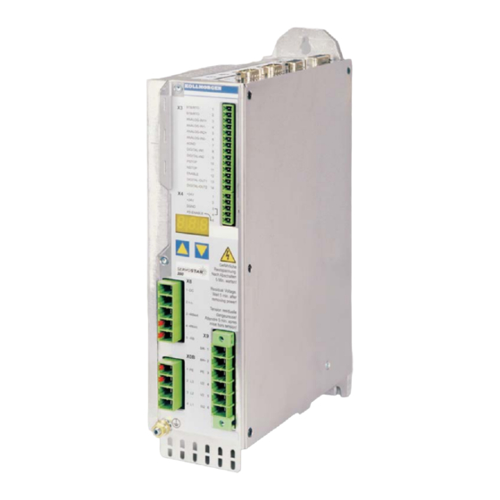
- Page 1 www.DanaherMotion.com Digital Servo Amplifier ® SERVOSTAR Assembly, Installation, Setup Keep all product manuals as a product component during the life span of the servo amplifier. Pass all product manuals to future users / owners of the servo amplifier. Edition 12/05 File sr300_e.xxx...
- Page 2 HIPERFACE is a registered trademark of Max Stegmann GmbH EnDat is a registered trademark of Dr. Johannes Heidenhain GmbH SERVOSTAR is a registered trademark of Danaher Motion Corporation Technical changes which improve the performance of the equipment may be made without prior...
-
Page 3: Table Of Contents
Kollmorgen Contents 12/05 page General About this manual ............... 7 Symbols used in this manual . - Page 4 Contents Kollmorgen 12/05 page Interfaces Block diagram ............... . . 39 Electrical supply .
- Page 5 Kollmorgen Contents 12/05 page Expansions and Accessories Expansion Cards ............... 75 6.1.1 Guide to installation of expansion cards.
- Page 6 Kollmorgen 12/05 This page has been deliberately left blank. ® SERVOSTAR 300 Installation Manual...
-
Page 7: General
Kollmorgen General 12/05 General About this manual ® This manual describes the SERVOSTAR 300 series of digital servo amplifiers (standard version: 1.5A ...10A rated current). In this manual you can find information about: General Chapter 1 Technical description Chapter 2 Assembly / installation Chapter 3 Interfaces... -
Page 8: Abbreviations Used In This Manual
General Kollmorgen 12/05 Abbreviations used in this manual The abbreviations used in this manual are explained in the table below. Abbrev. Meaning AGND Analog ground Restart lock, option BTB/RTO Ready to operate Fieldbus (CANopen) Communité Europeenne Clock signal Serial interface for a PC-AT DGND Digital ground (for 24V and digital I/O) German Institute for Industrial Standards... -
Page 9: Technical Description
Kollmorgen Technical description 12/05 Technical description Safety Instructions Only properly qualified personnel are permitted to perform activities such as transport, installation, setup and maintenance. Properly qualified persons are those who are familiar with the transport, assembly, installation, setup and operation of the product, and who have the appropriate qualifications for their job. -
Page 10: Use As Directed
Technical description Kollmorgen 12/05 Use as directed Servo amplifiers are components that are built into electrical plant or machines, and can only be operated as integral components of such plant or machines. The manufacturer of the machine must generate a hazard analysis for the machine, and take appropriate measures to ensure that unforeseen movements cannot cause injury or damage to any person or property. -
Page 11: European Directives And Standards
Kollmorgen Technical description 12/05 European Directives and Standards Servo amplifiers are components that are intended to be incorporated into electrical plant and machines for industrial use. When the servo amplifiers are built into machines or plant, the amplifier must not be used until it has been established that the machine or equipment fulfills the requirements of the EC Machinery Directive (98/37/EC), the EC EMC Directive (89/336/EEC) and the EC Low Voltage Directive 73/23/EEC. -
Page 12: Conformance With Ul And Cul
Technical description Kollmorgen 12/05 Conformance with UL and cUL This servo amplifier is listed under UL file number E217428. UL (cUL)-certified servo amplifiers (Underwriters Laboratories Inc.) fulfil the relevant U.S. and Canadian standard (in this case UL 840 and UL 508C). This standard describes the fulfilment by design of minimum requirements for electrically operated power conversion equipment, such as frequency converters and servo ampli- fiers, which is intended to eliminate the risk of fire, electric shock, or injury to persons,... -
Page 13: Nameplate
The nameplate depicted below is attached to the side of the servo amplifier. The information described below is printed in the individual fields. Expansion card Servo amplifier type Serial number and options Danaher Motion GmbH Customer Support Wacholderstr. 40-42 Europe Tel. +49 (0)203 / 99790 ®... -
Page 14: The Servostar 300 Family Of Digital Servo Amplifiers
Technical description Kollmorgen 12/05 2.7.2 The SERVOSTAR 300 family of digital servo amplifiers Standard version Two voltage classes with large nominal voltage range +10% 1 x 110V ... 3 x 230V (SERVOSTAR 303-310, S3xx6) -10% + 10% 3 x 208V ... - Page 15 Kollmorgen Technical description 12/05 Integrated safety Appropriate insulation/creepage distances and electrical isolation ensure safe electri- cal separation, as per EN 50178, between the power input / motor connections and the signal electronics Soft-start, overvoltage detection, short-circuit protection, phase-failure monitoring Temperature monitoring of the servo amplifier and motor (if our motors and prefabri- cated cables are used) Auxiliary supply voltage 24V DC Electrically isolated, internal fusing, from an external 24V DC power supply unit with,...
-
Page 16: Connection To Various Electrical Supply Networks
Technical description Kollmorgen 12/05 Connection to various electrical supply networks This page illustrates all the possible connection variations for different electrical supply networks. An isolating transformer is always required for 400 … 480V networks that are asymmetrically grounded or not grounded. 400V / 480V : SERVOSTAR 341-346* 110V : SERVOSTAR 303-310* 230V : all types... -
Page 17: Components Of A Servo System
Kollmorgen Technical description 12/05 Components of a servo system Controls / PLC SERVOSTAR 300 24V PSU Fuses Drive cut-out Terminals Motor ® SERVOSTAR 300 Installation Manual... -
Page 18: Technical Data
Technical description Kollmorgen 12/05 2.10 Technical data 2.10.1 Technical data for 110/230 V (types S3_ _6_) SERVOSTAR Rated data Order Code — S30361 S30661 S31061 1 x 110V … 1 x 230V +10% -10% Rated supply voltage 3 x 110V …... -
Page 19: Technical Data For 400/480 V (Types S3
Kollmorgen Technical description 12/05 2.10.2 Technical data for 400/480 V (types S3_ _0_) SERVOSTAR Rated data Order Code — S30101 S30301 S30601 Rated supply voltage 3 x 208V … 480V +10% , 50/60 Hz -10% (grounded supply, phase to phase) Rated input power for S1 operation Max. -
Page 20: Inputs / Outputs
Technical description Kollmorgen 12/05 2.10.3 Inputs / outputs ±10 Analog inputs 1, 2 (resolution 14/12 bit) ±10 Max. common-mode voltage Input resistance to AGND Digital control inputs as per EN 61131-2 Type 1, max. 30VDC Digital control outputs, active high open Emitter, max. -
Page 21: Permissible Ambient Temperatures, Ventilation, Mounting Position
+24 V / DGND max. 2.5 mm², check voltage drop For multi-axis systems, observe the specific operating conditions for your system * Danaher Motion North America supplies cables up to 39 meters Danaher Motion Europe supplies cables up to max. length 2.10.8... -
Page 22: Grounding System
Technical description Kollmorgen 12/05 2.11 Grounding system AGND — analog inputs, internal analog ground, encoder emulation, RS232, CAN DGND — digital inputs/outputs and the 24V supply, optically isolated. 2.12 Control circuit for motor-holding brake A 24V / max.1.5A holding brake in the motor can be controlled directly by the servo ampli- fier. -
Page 23: Regen Circuit
Kollmorgen Technical description 12/05 2.13 Regen circuit During braking with the aid of the motor, energy is fed back into the servo amplifier. This regenerative energy (hence the term “regen” circuit) is dissipated as heat in the regen resistor. The regen resistor is switched in by the regen circuit. The setup software can be used to adapt the regen circuit (thresholds) according to the electrical supply voltage. - Page 24 Technical description Kollmorgen 12/05 Technical Data: Regen circuit Supply voltage Rated data Dim. 110 V 230 V 400 V 480 V Switch-on (upper) threshold of regen circuit Overvoltage F02 Regen resistor (internal) Continuous power in regen circuit (RBint) — Pulse power in regen circuit (RBint max. 1s) 0,75 Regen resistor (external)* Continuous power in regen circuit (RBext) max.
-
Page 25: Switch-On And Switch-Off Behavior
Kollmorgen Technical description 12/05 2.14 Switch-on and switch-off behavior The diagram below illustrates the correct functional sequence for switching the servo amplifier on and off. DC bus link 2.14.1 Stop function as per EN 60204 (VDE 0113) If a fault occurs (ð p.72) then the output stage of the servo amplifier is switched off and the BTB/RTO contact is opened. -
Page 26: Emergency Stop Strategies
Technical description Kollmorgen 12/05 2.14.2 Emergency Stop strategies The Emergency Stop function is defined in EN 60204 (VDE 0113), Para. 9.2.5.4. Implementation of the Emergency Stop function : Wiring recommendation can be found in the Application Note “Stop and Emergency Stop Functions". -
Page 27: Installation
Kollmorgen Installation 12/05 Installation Important notes Protect the servo amplifier from impermissible stresses. In particular, do not let any components become bent or any insulation distances altered during transport and handling. Avoid contact with electronic components and contacts. Check the combination of servo amplifier and motor. Compare the rated voltage and current of the units. -
Page 28: Guide To Installation And Wiring
Installation Kollmorgen 12/05 Guide to installation and wiring The following notes should help you to carry out the installation in a sensible sequence, without overlooking anything important. In a closed control cabinet. Please refer to page 21. Site The site must be free from conductive or corrosive materials. For the mounting position in the cabinet ð... -
Page 29: Assembly
Kollmorgen Installation 12/05 Assembly Material: 3 x M5 hexagon socket screws to DIN 912 Tool required : 4 mm Allen key All dimensions in mm. SERVOSTAR ® SERVOSTAR 300 Installation Manual... -
Page 30: Dimensions
Installation Kollmorgen 12/05 3.3.1 Dimensions ® SERVOSTAR 300 Installation Manual... -
Page 31: Wiring
Kollmorgen Installation 12/05 Wiring Only professional staff who are qualified in electrical engineering are allowed to install the servo amplifier. The installation procedure is described as an example. A different procedure may be appropriate or necessary, depending on the application of the equipments. We provide further know-how through training courses (on request). -
Page 32: Connection Diagram
Installation Kollmorgen 12/05 3.4.1 Connection diagram Refer to the Safety Instructions (ð p.9) SERVOSTAR 300 and Use as Directed (ð p.10) ! ð S.44 ð S.46 ð p.50 ð S.46 ð S.47 ð p.43 ð p.51 ð p.42 ð p.52 ð... -
Page 33: Connector Assignments
Kollmorgen Installation 12/05 3.4.2 Connector assignments Þ p. 44 Þ p. 46 Þ p. 43 Þ p. 46 Þ p. 47 The connectors of the expansion card depend on used expansion card (see pages 76 ff). ® SERVOSTAR 300 Installation Manual... -
Page 34: Notes On Connection Technology
Installation Kollmorgen 12/05 3.4.3 Notes on connection technology 3.4.3.1 Shielding connection to the front panel Remove the outside shroud of the cable and the shielding braid on the desired core length. Secure the co- res with a cable tie. Remove the outside shroud of the line on a length from for instance 30mm without damaging the shiel- ding braid. -
Page 35: Technical Data For Connecting Cables
-30 / +80 (7x(2x0.25)) Encoder color -30 / +80 * Danaher Motion North America supplies cables up to 39 meters Danaher Motion Europe supplies cables up to max. length. Motor cables longer than 25m only with motor choke 3YLNxx ® SERVOSTAR... -
Page 36: Setup Software
Installation Kollmorgen 12/05 Setup software 3.5.1 General This chapter describes the installation of the setup software DRIVEGUI.EXE for the SERVOSTAR 300 digital servo amplifiers. We offer training and familiarization courses on request. 3.5.1.1 Use as directed The setup software is intended to be used for altering and saving the operating parameters for the SERVOSTAR 300 series of servo amplifiers. -
Page 37: Hardware Requirements
Kollmorgen Installation 12/05 3.5.1.3 Hardware requirements The PC interface (X6, RS232) of the servo amplifier is connected to the serial interface of the PC by a null-modem cable (not a null-modem link cable!) (ð p.59). Connect / disconnect the interface cable only when the electrical supply is switched off for both the PC and the servo amplifier. - Page 38 Installation Kollmorgen 12/05 This page has been intentionally left blank. ® SERVOSTAR 300 Installation Manual...
-
Page 39: Interfaces
Kollmorgen Interfaces 12/05 Interfaces All the important interfaces are presented in this chapter. The precise position of the con- nectors and terminals can be seen on page 33. The block diagram below just provides an overview. Block diagram ® SERVOSTAR 300 Installation Manual... -
Page 40: Electrical Supply
Interfaces Kollmorgen 12/05 Electrical supply 4.2.1 Mains electrical supply connection (X0) 4.2.1.1 Three phase — Directly to 3-phase supply network, filter is integrated Fusing (e.g. fusible cut-outs) to be provided by the user ð p.20 — SERVOSTAR 300 4.2.1.2 Single phase without neutral SERVOSTAR 300 4.2.1.3 Single phase with neutral... -
Page 41: Auxiliary Supply (X4)
Kollmorgen Interfaces 12/05 4.2.2 24V auxiliary supply (X4) — External 24V DC power supply, electrically isolated, e.g. via an isolating transformer — Required current rating ð p.18 — Integrated EMC filter for the 24V auxiliary supply SERVOSTAR 300 4.2.3 DC bus link (X8) Terminals X8/1 (-DC) and X8/3 (+RBext). -
Page 42: Motor Connection With Brake (X9)
Interfaces Kollmorgen 12/05 Motor connection with brake (X9) Cable length £ 25 meters SERVOSTAR 300 Cable length >25 meters For cable lengths above 25m up to max. 50m, the motor choke 3YLNxx (ð S.93) must be wired into the motor cable, close to the amplifier. SERVOSTAR 300 External regen resistor (X8) Remove the plug-in link between the terminals X8/5 (-R... -
Page 43: Feedback
Kollmorgen Interfaces 12/05 Feedback Feedback system Conn. Remarks Resolver p. 43 2 to 36 poles ComCoder p. 44 A, B, zero, Hall Incremental or sine Encoder A, B, zero, Hall or p. 45 with Hall Sine, Cosine, zero, Hall Encoder with EnDat/HIPERFACE p. -
Page 44: Comcoder (X1)
Interfaces Kollmorgen 12/05 4.5.2 Comcoder (X1) As an option our motors can be equipped with a ComCoder as feedback unit. For the commutation hall sensors are used and for the resolution an incremental encoder. The thermostat contact in the motor is connected via the ComCoder cable to X1 and evaluated there. -
Page 45: Incremental Or Sine Encoder With Hall Sensors (X1)
Kollmorgen Interfaces 12/05 4.5.3 Incremental or sine encoder with hall sensors (X1) Feedback devices (incremental or sine-cosine), which don't deliver an absolute informa- tion for commutation, can be used as complete feedback system combined with an addi- tional Hall encoder. All signals are connected to X1. If cable lengths of more than 25m are planned, please consult our customer service. -
Page 46: Encoder With Endat Or Hiperface (X1)
Interfaces Kollmorgen 12/05 4.5.4 Encoder with EnDat or HIPERFACE (X1) As an option, our servomotors can be fitted with a single-turn or multi-turn sine-cosine encoder. Preferred types are the ECN1313 and EQN1325 encoders. The encoder is used by the SERVOSTAR 300 as a feedback device for drive tasks that require highly precise positioning or extremely smooth running. -
Page 47: Acuro Encoder, Biss Interface (X1)
Kollmorgen Interfaces 12/05 4.5.5 ACURO encoder, BISS interface (X1) As an option, our servomotors can be fitted with a single-turn or multi-turn ACURO enco- der with BISS interface. The encoder is used by the SERVOSTAR 300 as a feedback device for drive tasks that require highly precise positioning or extremely smooth running. -
Page 48: Incremental Encoder (X5)
Interfaces Kollmorgen 12/05 4.5.6 Incremental Encoder (X5) An incremental encoder can be used as standard motor feedback. Select feedback type 19 "ROD 5V with W&S". Drive executes wake&shake to calculate the necessary start-up information for the position controller every time the 24V auxiliary voltage is switched on. -
Page 49: Encoder Without Data Channel (X1)
Kollmorgen Interfaces 12/05 4.5.7 Encoder without data channel (X1) An sine-cosine encoder without data channel can be used as standard motor feedback. Select feedback type 7 "SinCos 5V with W&S". Drive executes wake&shake to calculate the necessary start-up information for the position controller every time the 24V auxiliary voltage is switched on. -
Page 50: Control Signals
Interfaces Kollmorgen 12/05 Control signals 4.6.1 Analog inputs (X3) The servo amplifier is fitted with two programmable differential inputs for analog set- points. AGND (X3/7) must always be joined to the GND of the controls as a ground reference. Technical characteristics —... -
Page 51: Digital Inputs (X3/X4)
Kollmorgen Interfaces 12/05 4.6.2 Digital inputs (X3/X4) All digital inputs are electrically isolated via optocouplers. Technical characteristics — Ground reference is Digital-GND (DGND, terminals X4/3 and X4/4) — The inputs at X3 are PLC-compatible (IEC 61131-2 Type 1) High: 11...30 V / 2...11 mA , Low: -3...5 V / <1mA —... -
Page 52: Digital Outputs (X3)
Interfaces Kollmorgen 12/05 4.6.3 Digital outputs (X3) Technical characteristics — Ground reference is Digital-GND (DGND, terminals X4/3 and X4/4) — All digital outputs are floating — DIGITAL-OUT1 and 2 : Open Emitter, max. 30V DC, 10mA BTB/RTO : Relay output, max. 30V DC or 42V AC, 0.5A —... -
Page 53: Encoder Emulation
Kollmorgen Interfaces 12/05 Encoder emulation 4.7.1 Incremental encoder output (X5) The incremental-encoder interface is part of the package supplied. Select encoder function ROD (A Quad B) Encoder (“Encoder Emulation” screen page). The servo ampli- fier calculates the motor shaft position from the cyclic- absolute signals of the resolver or encoder, generating incremental-encoder compatible pulses from this information. -
Page 54: Ssi Output (X5)
Interfaces Kollmorgen 12/05 4.7.2 SSI output (X5) The SSI interface (synchronous serial absolute-encoder emulation) is part of the package supplied. Select encoder function SSI (“Encoder Emulation” screen page). The servo amplifier calculates the motor shaft position from the cyclic-absolute signals of the resol- ver or encoder. -
Page 55: Master-Slave Operation, Encoder Master Control
Kollmorgen Interfaces 12/05 Master-slave operation, encoder master control This interface can be used to link several SERVOSTAR 300 amplifiers together in mas- ter-slave operation. Parameter setting for the slave amplifier is carried out with the aid of the setup software (electrical gearing). -
Page 56: Connection To Incremental-Encoder Master With 24V Signal Level (X3)
Interfaces Kollmorgen 12/05 4.8.2 Connection to incremental-encoder master with 24V signal level (X3) This interface can be used to operate the SERVOSTAR as a slave, mastered by an enco- der with a 24V signal level (master-slave operation). This uses the digital inputs DIGITAL-IN 1 and 2 on connector X3. Frequency limit: 100 kHz, transition time tv £... -
Page 57: Interface For Stepper Motor Controllers (Step And Direction)
Kollmorgen Interfaces 12/05 Interface for stepper motor controllers (step and direction) This interface can be used to connect the servo amplifier to a third-party stepper-motor controller. Parameter setting for the slave amplifier is carried out with the aid of the setup software (electrical gearing). -
Page 58: Connection To A Stepper Controller With 5V Signal Level (X5)
Interfaces Kollmorgen 12/05 4.9.1 Connection to a stepper controller with 5V signal level (X5) This interface can be used to connect the servo amplifier to a stepper-motor controller with a 5V signal level. It uses the SubD connector X5. Frequency limit: 1.5 MHz SERVOSTAR 300 4.9.2 Connection to a stepper controller with 24V signal level (X3) -
Page 59: Rs232 Interface, Pc Connection (X6)
Kollmorgen Interfaces 12/05 4.10 RS232 interface, PC connection (X6) Operating, position control, and motion-block parameters can be set up by using the setup software on an ordinary commercial PC. Connect the PC interface (X6) of the servo amplifier to a serial interface on the PC via a null-modem cable, while the supply to the equipment is switched off. -
Page 60: Canopen Interface (X6)
Interfaces Kollmorgen 12/05 4.11 CANopen interface (X6) The interface for connection to the CAN-bus (default : 500 kBaud). The integrated profile is based on the CANopen DS301 communication profile and the DS402 drive profile. The following functions are available in connection with the position controller: Jogging with variable speed, homing run (zeroing to reference), start motion task, start direct task, digital setpoint provision, data transmission functions and many others. -
Page 61: Personnel Safe Restart Lock -As
Kollmorgen Interfaces 12/05 4.12 Personnel safe restart lock -AS- A frequently required application task is the protection of personnel against the restarting of drives. This can be achieved by an electronic inhibit or with mechanical elements (posi- tively driven relay contacts). When positively driven relay contacts where used, either the net contactor in the mains supply circuit switched off or the motor was disconnected from the servo amplifier by an additional contactor. -
Page 62: Functional Description
Interfaces Kollmorgen 12/05 4.12.4 Functional description If the restart lock -AS- is not needed, then the input AS-ENABLE must be connected directly with +24VDC. The restart lock is then passed by and cannot not be used. In case of use of the restart lock the input AS Enable must be connected to the exit of a security control or a safety relay, which meets at least to the requirements of the category 3 after EN 954-1 (see the connection diagram on page 64). -
Page 63: Signal Diagram (Sequence)
Kollmorgen Interfaces 12/05 4.12.4.1 Signal diagram (sequence) The diagram shows how to use restart lock -AS- to ensure a safe stop of the drive and error free operation of the servo amplifier. Brake the drive in a controlled manner (speed setpoint = 0V) When speed = 0 rpm, disable the servo amplifier (Enable = 0V) Activate the restart lock -AS- (AS-Enable = 0V) Suspended loads can set themselves to motion on motors without brake, because... -
Page 64: Control Circuit
Interfaces Kollmorgen 12/05 4.12.4.2 Control circuit Emergency-stop circuit acc. to EN 954-1 category 4 Safe stop acc. to EN954-1 category 3 for 3 drives Safe stop acc. to EN 954-1 category 3 for 2 drives The example shows a circuit diagram with two separated work areas connected to one emergency stop circuit. -
Page 65: Functional Test
Kollmorgen Interfaces 12/05 4.12.4.3 Functional test With initial starting and after each interference into the wiring of the drive or after exchange of one or several components of the drive the function of the restart lock must be tested. 1. Method: 1. - Page 66 Interfaces Kollmorgen 12/05 This page has been deliberately left blank. ® SERVOSTAR 300 Installation Manual...
-
Page 67: Setup
Kollmorgen Setup 12/05 Setup Important notes Only professional personnel with extensive knowledge in the fields of electrical engineering and drive technology are allowed to setup the servo amplifier. The procedure for setup is described as an example. Depending on the application, a dif- ferent procedure may be appropriate or necessary. -
Page 68: Guide To Setup
Setup Kollmorgen 12/05 Guide to setup The following instructions should help you to carry out the setup in a sensible order, wit- hout endangering people or machinery. Check installation See Ch. 3. Disconnect the servo amplifier from the supply. Block the Enable Apply 0V to terminal X3/12 (Enable) and signals to terminal X4/5 (AS-Enable) -
Page 69: Parameter Setting
Kollmorgen Setup 12/05 Parameter setting A default parameter set has been loaded into your servo amplifier by the manufacturer. This contains valid and safe parameters for the current and speed controllers. A database for motor parameters is stored in the servo amplifier. During setup you must select the data set for the motor that is connected and store it in the servo amplifier. -
Page 70: Keypad Operation
Setup Kollmorgen 12/05 5.3.2.1 Keypad operation The two keys can be used to perform the following functions: Key symbol Functions press once : move up one menu item, increase number by one press twice in rapid succession : increase number by ten press once : move down one menu item, decrease number by one press twice in rapid succession : decrease number by ten hold right key pressed, and then press left key as well :... -
Page 71: Standard Menu
Kollmorgen Setup 12/05 5.3.2.3 Standard menu ð p.69 5.3.2.4 Advanced menu ð p.69 ð p.69 ® SERVOSTAR 300 Installation Manual... -
Page 72: Error Messages
Setup Kollmorgen 12/05 Error messages Any errors that occur are shown in coded form by an error number in the LED display on the front panel. All error messages result in the BTB/RTO contact being opened, and the output stage of the amplifier being switched off (motor loses all torque), and the motor-holding brake is activated. -
Page 73: Warning Messages
Kollmorgen Setup 12/05 Warning messages Faults which occur, but which do not cause a switch-off of the amplifier output stage (BTB/RTO contact remains closed), are indicated in the LED display on the front panel by a coded warning number. Number Designation Explanation E / S / A / P Status Messages... - Page 74 Setup Kollmorgen 12/05 This page has been intentionally left blank. ® SERVOSTAR 300 Installation Manual...
-
Page 75: Expansions And Accessories
Kollmorgen Expansions and Accessories 12/05 Expansions and Accessories You can find information about availability and order numbers on page 101. Expansion Cards 6.1.1 Guide to installation of expansion cards Use a suitable screwdriver to lever off the cover of the option slot. Take care that no small items (such as screws) fall into the open option slot. -
Page 76: Expansion Card -I/O-14/08
Expansions and Accessories Kollmorgen 12/05 6.1.2 Expansion card -I/O-14/08- This section describes the additional features that the expansion card -I/O-14/08- provi- des for the SERVOSTAR 300. If you ordered the expansion card together with the servo amplifier, then it will be delivered already inserted into the expansion slot of the servo amplifier and screwed in place. -
Page 77: Connector Assignments
Kollmorgen Expansions and Accessories 12/05 6.1.2.5 Connector assignments The functions are adjustable with the setup software. In the table below the default values are described. Connector X11A Default Pin Dir Description function Motion block number, LSB Motion block number, 2 Motion block number, 2 Motion block number, 2 Motion block number, 2... -
Page 78: Connection Diagram
Expansions and Accessories Kollmorgen 12/05 6.1.2.6 Connection diagram SERVOSTAR 300 ® SERVOSTAR 300 Installation Manual... -
Page 79: Expansion Card -Profibus
Kollmorgen Expansions and Accessories 12/05 6.1.3 Expansion card -PROFIBUS- This section describes the PROFIBUS expansion card for the SERVOSTAR 300. Information on the range of functions and the software protocol can be found in our manual “Communication Profile PROFIBUS DP”. If you ordered the expansion card together with the servo amplifier, then the expansion card is already fitted and screwed into the slot when the servo amplifier is delivered. -
Page 80: Expansion Card -Sercos
Expansions and Accessories Kollmorgen 12/05 6.1.4 Expansion card -SERCOS- This section describes the SERCOS expansion card for SERVOSTAR 300. Information on the range of functions and the software protocol can be found in our manual “IDN Reference Guide SERCOS”. If you ordered the expansion card together with the servo amplifier, then the expansion card is already fitted and screwed into the slot when the servo amplifier is delivered. -
Page 81: Connection Diagram
Kollmorgen Expansions and Accessories 12/05 6.1.4.4 Connection diagram Layout of the SERCOS bus system in ring topology, with optical fiber cables (schematic). 6.1.4.5 Modifying the station address The drive address can be set to a value between 0 and 63. With address 0, the drive is assigned as an amplifier in the SERCOS ring. -
Page 82: Expansion Card -Devicenet
Expansions and Accessories Kollmorgen 12/05 6.1.5 Expansion card -DEVICENET- This section describes the DeviceNet expansion card for SERVOSTAR 300. Information on the range of functions and the software protocol can be found in our manual “DeviceNet Communication Profile”. If you ordered the expansion card together with the servo amplifier, then the expansion card is already fitted and screwed into the slot when the servo amplifier is delivered.. -
Page 83: Combined Module/Network Status-Led
Kollmorgen Expansions and Accessories 12/05 6.1.5.4 Combined module/network status-LED Meaning The device is not online. The device has not yet finished the Dup_MAC_ID test. The device is possibly not yet switched on. The device is operating as normal, is online, and the connections have been green established. -
Page 84: Bus Cable
Expansions and Accessories Kollmorgen 12/05 6.1.5.7 Bus cable To meet ISO 898, a bus cable with a characteristic impedance of 120 W should be used. The maximum usable cable length for reliable communication decreases with increasing transmission speed. As a guide, you can use the following values which we have measu- red, but they are not to be taken as assured limits. -
Page 85: Expansion Card -Ethercat
Kollmorgen Expansions and Accessories 12/05 6.1.6 Expansion card -ETHERCAT- This section describes the EtherCat expansion card for SERVOSTAR 300. Information on the range of functions and the software protocol can be found in the Ether- Cat documentation. This expansion cards enables the servo amplifier to be connected to the EtherCat network (Beckhoff company). -
Page 86: Expansion Card -Synqnet
Expansions and Accessories Kollmorgen 12/05 6.1.7 Expansion card -SYNQNET- This section describes the SynqNet expansion card for SERVOSTAR 300. Information on the range of functions and the software protocol can be found in the SynqNet documentation. If you ordered the expansion card together with the servo amplifier, then the expansion card is already fitted and screwed into the slot when the servo amplifier is delivered. -
Page 87: Digital Inputs/Outputs, Connector X21A (Subd 15-Pin, Socket)
Kollmorgen Expansions and Accessories 12/05 6.1.7.5 Digital inputs/outputs, connector X21A (SubD 15-pin, socket) Inputs (In): 24V (20...28V), opto-isolated, one high-speed input (Pin 4) Outputs (Out): 24V, opto-isolated, Darlington driver Pinout connector X21A (SubD 15 pin) Pin Type Description Pin Type Description +24V power supply power supply... -
Page 88: Expansion Module -2Can
Expansions and Accessories Kollmorgen 12/05 6.1.8 Expansion module -2CAN- Connector X6 of the SERVOSTAR is assigned to the signals for the RS232 interface and the CAN interface. It is therefore not the standard pin assignment for these interfaces, and a special cable is required to be able to use both interfaces simultaneously. The -2CAN- expansion module provides the interfaces on separate Sub-D connectors. -
Page 89: Connector Assignments
Kollmorgen Expansions and Accessories 12/05 6.1.8.4 Connector assignments RS232 CAN1=CAN2 X6A Pin Signal X6B=X6C Pin Signal CAN-Low CAN-GND CAN-High 6.1.8.5 Connection diagram ® SERVOSTAR 300 Installation Manual... -
Page 90: Accessories
Expansions and Accessories Kollmorgen 12/05 Accessories 6.2.1 External power supply 24V DC / 5A Technical data (not available in North America) Input voltage 120 / 230V Input current 0.9 / 0.6A Frequency 50/60Hz Primary fusing 3.15AT Output voltage 24V ± 1% Max. -
Page 91: External Power Supply 24V Dc / 20A
Kollmorgen Expansions and Accessories 12/05 6.2.2 External power supply 24V DC / 20A Mounting Plate (not available in Technical data North America) Input voltage 3 x 400V AC ± 10% Input current approx. 1.1A Frequency 50/60Hz Primary fusing none Output voltage 24V ±... -
Page 92: External Regen Resistor Bar(U)Xxx
Expansions and Accessories Kollmorgen 12/05 6.2.3 External regen resistor BAR(U)xxx Caution: The surface temperature can exceed 200°C. Make sure that the necessary space is kept clear. Do not mount the instrument on combustible surfaces! ® SERVOSTAR 300 Installation Manual... -
Page 93: Motor Chokes 3Ylnxx
Kollmorgen Expansions and Accessories 12/05 6.2.4 Motor chokes 3YLNxx To use with motor cables longer than 25m up to 50m max. to reduce velocity ripple and to protect the output power stage of the amplifier. The terminals BR are used to connect the motor holding brake. - Page 94 Expansions and Accessories Kollmorgen 12/05 This page has been deliberately left blank ® SERVOSTAR 300 Installation Manual...
-
Page 95: Appendix
Kollmorgen Appendix 12/05 Appendix Transport, storage, maintenance, disposal Transport : — only by qualified personnel — only in the manufacturer’s original recyclable packaging — avoid shocks — temperature -25 to +70°C, max. rate of change 20°C / hour — humidity max. -
Page 96: Finding And Removing Faults
Appendix Kollmorgen 12/05 Finding and removing faults The table below should be regarded as a “First-aid” box. There may be a wide variety of reasons for the fault, depending on the conditions in your installation. In multi-axis systems there may be further hidden causes of a fault. Our customer service can give you further assistance with problems. - Page 97 Kollmorgen Appendix 12/05 Fault Possible causes Measures — short-circuit in the supply cable — remove the short-circuit for the motor-holding brake — motor-holding brake is faulty — replace motor F11 message: Brake — fault in brake cable — check shielding of brake cable —...
- Page 98 Appendix Kollmorgen 12/05 Fault Possible causes Measures — Kp (speed controller) too low — increase Kp (speed controller) — Tn (speed controller) too high — use motor default value for Tn (speed controller) Drive too soft — ARLPF / ARHPF too high —...
-
Page 99: Glossary
Kollmorgen Appendix 12/05 Glossary Clock Clock signal Common-mode voltage The maximum amplitude of a disturbance (on both inputs) which a differential input can eliminate CONNECT modules Modules built into the servo amplifier, with integra- ted position control, that provide special versions of the interface for the connection to the higher- level control. - Page 100 Appendix Kollmorgen 12/05 Optocoupler Optical connection between two electrically independent systems P-controller Control loop with purely proportional behavior Phase shift Compensation for the lag between the electro- magnetic and magnetic fields in the motor PI-controller Control loop with proportional and differential behavior Position controller Regulates the difference between the position...
-
Page 101: Order Codes
Refer to information Motor cable (230V) 20m (4x1+(2x0,75)) DE-107494 in the US brochure, to DE-107495 Motor cable (230V) 25m (4x1+(2x0,75)) the Danaher Motion Motor cable (400V) 5m (4x1) DE-107473 Website or ask our Motor cable (400V) 10m (4x1) DE-107474 sales representative. -
Page 102: Feedback Cables With Connectors
DE-90287 Encoder cable 5m (7x(2x0.25)) in the US brochure, to Encoder cable 10m (7x(2x0.25)) DE-91019 Encoder cable 15m (7x(2x0.25)) DE-91811 the Danaher Motion Encoder cable 20m (7x(2x0.25)) DE-91807 Website or ask our Encoder cable 25m (7x(2x0.25)) DE-92205 sales representative. DE-107915 Comcoder cable 5m (8x(2x0.25)) -
Page 103: Index
Kollmorgen Appendix 12/05 Index maintenance ....95 24V aux. supply, interface ..41 master-slave ....55 ACURO (BISS), interface . - Page 104 If you are unaware of your local sales representative, please contact us. Europe Visit the European Danaher Motion web site at www.DanaherMotion.net for Setup Software upgrades, application notes, technical publications and the most recent version of our product manuals. Danaher Motion Customer Support - Europe Internet www.DanaherMotion.net...
Need help?
Do you have a question about the Kollmorgen SERVOSTAR 300 Series and is the answer not in the manual?
Questions and answers