Dräger Narkomed 3 Technical & Service Manual
Anesthesia system
Hide thumbs
Also See for Narkomed 3:
- Operator's instruction manual (104 pages) ,
- Replacement (14 pages)
Table of Contents
Troubleshooting

Related Manuals for Dräger Narkomed 3


Summary of Contents for Dräger Narkomed 3
- Page 1 RETURN TO THIS MANUAL'S TABLE OF CONTENTS RETURN TO CD-ROM TABLE OF CONTENTS DrägerService ® Technical Service Manual Part Number: S002013 Rev: V Date: 20 May 2002 © 2002 Draeger Medical, Inc. Narkomed 3 Anesthesia System...
- Page 2 RETURN TO THIS MANUAL'S TABLE OF CONTENTS RETURN TO CD-ROM TABLE OF CONTENTS...
-
Page 3: Table Of Contents
RETURN TO CD-ROM TABLE OF CONTENTS DrägerService ® Narkomed 3 Service Manual Table of Contents Summary of What's New in Rev. B DESCRIPTION PAGE SECTION 1: Introduction ............ - Page 4 RETURN TO THIS MANUAL'S TABLE OF CONTENTS RETURN TO CD-ROM TABLE OF CONTENTS CONTENTS (continued) DESCRIPTION PAGE 4.25 CRT Asemblies ......... . 4-91 4.26 Keypads .
- Page 5 RETURN TO THIS MANUAL'S TABLE OF CONTENTS RETURN TO CD-ROM TABLE OF CONTENTS CONTENTS (continued) DESCRIPTION PAGE 6.17 PEEP Bypass Valve ........6-25 6.18 Ventilator Test .
- Page 6 RETURN TO THIS MANUAL'S TABLE OF CONTENTS RETURN TO CD-ROM TABLE OF CONTENTS CONTENTS (continued) SECTION 8: Spare and Replacement Parts ASSEMBLY/PART PAGE Monitor Chassis, Monitors, CCC, Trend/MUX, CRT Assemblies ....8-2, 8-3 Front Bezel Assembly, Serial Interface Assembly .
- Page 7 RETURN TO THIS MANUAL'S TABLE OF CONTENTS RETURN TO CD-ROM TABLE OF CONTENTS...
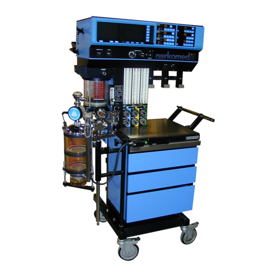
- Page 8 RETURN TO THIS MANUAL'S TABLE OF CONTENTS RETURN TO CD-ROM TABLE OF CONTENTS NARKOMED 3 ANESTHESIA SYSTEM BOOM ARM ALARM AND DATA DISPLAY SCREENS SYSTEM CONTROL KEYPAD PATIENT INTERFACE PANEL MONITORS MANUAL SPHYGMOMANOMETER (OPTIONAL) BREATHING SYSTEM SENSOR INTERFACE PANEL SV30101...
-
Page 9: Introduction
The PMS PROCEDURE in Section 6 must also be performed after any component has been replaced. The general arrangement of the Narkomed 3 Anesthesia System is shown on the opposite page. WARNINGS are used in this manual before procedures which if not performed correctly could result in personal injury. - Page 10 RETURN TO THIS MANUAL'S TABLE OF CONTENTS RETURN TO CD-ROM TABLE OF CONTENTS INTRODUCTION Copyright Copyright © 1997 by Draeger Medical, Inc. All rights reserved. No part of this publication may be reproduced, transmitted, transcribed, or stored in a retrieval system in any form or by any means, electronic or mechanical, including photocopying and recording, without the written permission of Draeger Medical, Inc.
-
Page 11: 2.0 Diagnostics
DIAGNOSTICS 2.0 DIAGNOSTICS When the Narkomed 3 is powered up, each of the monitors performs a six-second self- diagnostic check and lamp test. The display window on each monitor should show a power-up code number, and all LED indicators and backlit labels should illuminate. The left-hand CRT will then show the Centralert Alarm display and the right-hand CRT will show the Data display. -
Page 12: Service Selection Screen
RETURN TO THIS MANUAL'S TABLE OF CONTENTS RETURN TO CD-ROM TABLE OF CONTENTS DIAGNOSTICS (continued) Service Selection Screen To access the Service Selection Screen, press and hold the LOG DATA key and the hidden key directly to the right of the LOG DATA key, then press the CHECKOUT key. -
Page 13: Configuration Screen
RETURN TO THIS MANUAL'S TABLE OF CONTENTS RETURN TO CD-ROM TABLE OF CONTENTS DIAGNOSTICS (continued) Configuration Screen To access the Configuration Screen, press the SELECT key (see Figure 2-1) to advance the cursor to the CONFIGURE DEFAULTS option, and then press the ENTER key. -
Page 14: Service Data Screen
RETURN TO THIS MANUAL'S TABLE OF CONTENTS RETURN TO CD-ROM TABLE OF CONTENTS DIAGNOSTICS (continued) Service Data Screen To access the Service Data Screen, press the SELECT key (see Figure 2-1) to advance the cursor to the SERVICE DATA option, and then press the ENTER key. -
Page 15: Troubleshooting
Power Supply and Voltage Distribution In the NARKOMED 3, power for the monitors and CRT displays is distributed from a terminal block located in the rear of the monitor housing. This terminal block is accessible by opening the back cover of the monitor housing. Figure 3-1 shows the terminal block inputs and main DC power wiring harness connections to the power controller PCB assembly. - Page 16 RETURN TO THIS MANUAL'S TABLE OF CONTENTS RETURN TO CD-ROM TABLE OF CONTENTS TROUBLESHOOTING GUIDE (continued) POWER DISTRIBUTION TERMINAL BLOCK IN MONITOR HOUSING 5 6 7 10 11 14 15 16 17 18 19 20 21 22 23 24 25 26 +7.4 V -8 V +12 V NV +8 V NV...
- Page 17 RETURN TO THIS MANUAL'S TABLE OF CONTENTS RETURN TO CD-ROM TABLE OF CONTENTS TROUBLESHOOTING GUIDE (continued) BACKPLANES DATA CRT ALARM CRT +8 VITAL +8 VITAL J5-1 J5-1 J5-1 +8 VITAL J5-2 J5-2 J5-2 +7.4 J5-3 J5-3 J5-3 J5-4 J5-1 +8 VITAL J5-2 +7.4 J5-3...
-
Page 18: Multispec Analyzer Power Supply
RETURN TO THIS MANUAL'S TABLE OF CONTENTS RETURN TO CD-ROM TABLE OF CONTENTS TROUBLESHOOTING GUIDE (continued) Multispec Analyzer Power Supply The multispec analyzer is powered by a separate supply located in the secondary power supply compartment directly above the power controller PCB assembly. -
Page 19: Troubleshooting Guide Flow Charts
Technical Service Representative in locating a problem. These flow charts assume that the machine is plugged into an AC outlet with the correct voltage, and the machine is not running on its backup battery. Table 3-3: NARKOMED 3 TROUBLESHOOTING GUIDES FAILURE MODE / SYMPTOM CORRECTIVE ACTION... - Page 20 RETURN TO THIS MANUAL'S TABLE OF CONTENTS RETURN TO CD-ROM TABLE OF CONTENTS TROUBLESHOOTING GUIDE (continued) GUIDE 1: CRT Screen Blank or Incorrect Display START SCREEN BLANK? DISPLAY CORRECT? CONNECT ALL ALL CRT ASM CRT ASM CABLES PLUGGED IN CABLES AT BOTH ENDS? REPLACE TREND ASM...
- Page 21 RETURN TO THIS MANUAL'S TABLE OF CONTENTS RETURN TO CD-ROM TABLE OF CONTENTS TROUBLESHOOTING GUIDE (continued) GUIDE 2: O2MED Monitor Inoperative START POWER-UP "O2MED ERR" LAMP TEST OR "O2 CAL" MSG ON ALARM CRT? CHECK EXTERNAL AND INTERNAL PLUG MONITOR MONITOR SENSOR CABLE FIRMLY INTO...
- Page 22 RETURN TO THIS MANUAL'S TABLE OF CONTENTS RETURN TO CD-ROM TABLE OF CONTENTS TROUBLESHOOTING GUIDE (continued) GUIDE 3: BAROMED Monitor Inoperative START ERROR CODE POWER-UP IN MONITOR WINDOW ERRONEOUS OR LAMP TEST OR "BAROMED ERR" MSG UNSTABLE READINGS? ON ALARM CRT? CHECK EXTERNAL AND INTERNAL PLUG MONITOR...
- Page 23 RETURN TO THIS MANUAL'S TABLE OF CONTENTS RETURN TO CD-ROM TABLE OF CONTENTS TROUBLESHOOTING GUIDE (continued) GUIDE 4: SaO2 Monitor Inoperative START ERROR CODE IN POWER-UP MONITOR WINDOW, "OXI DISC", LAMP TEST "O2SATMED ERR" OR "OXI ALRM OFF" MSG "OXIMETER ERR" MSG ON ALARM CRT? ON ALARM CRT? PLUG MONITOR...
- Page 24 RETURN TO THIS MANUAL'S TABLE OF CONTENTS RETURN TO CD-ROM TABLE OF CONTENTS TROUBLESHOOTING GUIDE (continued) GUIDE 5: SPIROMED Monitor Inoperative START ERROR CODE "VOL SEN DISC" POWER-UP IN MONITOR WINDOW MSG ON ALARM LAMP TEST OR "SPIROMED ERR" MSG CRT? ON ALARM CRT? CHECK...
- Page 25 RETURN TO THIS MANUAL'S TABLE OF CONTENTS RETURN TO CD-ROM TABLE OF CONTENTS TROUBLESHOOTING GUIDE (continued) GUIDE 6: SPHYGMOMED Monitor Inoperative START ERROR CODE IN BP ERROR POWER-UP MONITOR WINDOW, INDICATOR, "BP CUFF LAMP TEST "SPHYGMOM ERR" MSG DISC" OR "BP CUFF ERR" MSG ON ALARM CRT? ON ALARM CRT? PLUG MONITOR...
- Page 26 RETURN TO THIS MANUAL'S TABLE OF CONTENTS RETURN TO CD-ROM TABLE OF CONTENTS TROUBLESHOOTING GUIDE (continued) GUIDE 7: MULTISPEC Monitor and Analyzer Errors START POWER-UP ERROR CODE ERROR CODE LAMP TEST E07 IN MONITOR E06 IN MONITOR WINDOW? WINDOW? PLUG MONITOR FIRMLY INTO BACKPLANE CHECK MONITOR...
- Page 27 RETURN TO THIS MANUAL'S TABLE OF CONTENTS RETURN TO CD-ROM TABLE OF CONTENTS TROUBLESHOOTING GUIDE (continued) GUIDE 7 (continued): MULTISPEC Monitor and Analyzer Errors OTHER ERROR LOW END SLOW CODES IN MONITOR TIDAL VOL AND INSP RESPONSE TIME? WINDOW? CO2 READINGS? CHECK FOR RECALIBRATE SAMPLE LINE...
- Page 28 RETURN TO THIS MANUAL'S TABLE OF CONTENTS RETURN TO CD-ROM TABLE OF CONTENTS TROUBLESHOOTING GUIDE (continued) GUIDE 8: Serial Interface Communication Failure START SERIAL PORT COMM FAILURE? CONNECT EXTERNAL COMM CABLE REINSTALL ORIGINAL EXTERNAL ECC MODULE CABLE CONNECTED ----------------------------- TO SERIAL PORT? REPLACE CCC ASM AS OUTLINED IN CHECK POWER...
- Page 29 RETURN TO THIS MANUAL'S TABLE OF CONTENTS RETURN TO CD-ROM TABLE OF CONTENTS TROUBLESHOOTING GUIDE (continued) GUIDE 9: Loss of Keypad Response START CORRECT KEYPAD RESPONSE? PLUG IN OUTBOARD END OF KEYPAD CABLE KEYPAD CABLE PLUGGED IN? SUBSTITUTE REPLACEMENT KEYPAD CORRECT REPLACE KEYPAD KEYPAD...
- Page 30 RETURN TO THIS MANUAL'S TABLE OF CONTENTS RETURN TO CD-ROM TABLE OF CONTENTS...
-
Page 31: Replacement Procedures
REPLACEMENT PROCEDURES REPLACEMENT PROCEDURES This section outlines removal and replacement procedures for the field-replaceable assemblies of the NARKOMED 3 Anesthesia System. These procedures are to be performed only by a Draeger Medical, Inc. qualified Technical Service Representative (TSR). The following are the only procedures authorized by Draeger Medical, Inc. to be performed in the field. -
Page 32: Cylinder Yoke Assemblies
RETURN TO THIS MANUAL'S TABLE OF CONTENTS RETURN TO CD-ROM TABLE OF CONTENTS REPLACEMENT PROCEDURES (continued) Cylinder Yoke Assemblies Each cylinder yoke contains a replaceable filter and check valve assembly. Replacement of this assembly requires that the yoke be removed from the anesthesia machine. - Page 33 RETURN TO THIS MANUAL'S TABLE OF CONTENTS RETURN TO CD-ROM TABLE OF CONTENTS REPLACEMENT PROCEDURES (continued) YOKE ASSEMBLY (TYPICAL) YOKE SPACER FILTER AND CHECK VALVE ASSEMBLY SV40601 GAS LINE Figure 4-1: CYLINDER YOKE ASSEMBLY Rev. G...
- Page 34 RETURN TO THIS MANUAL'S TABLE OF CONTENTS RETURN TO CD-ROM TABLE OF CONTENTS REPLACEMENT PROCEDURES (continued) 4.1.12 Position the yoke on the spacer, and install the two mounting screws and lockwashers. Tighten the screws securely. Connect the gas line fitting to the yoke. 4.1.13 If a new cylinder is being installed, remove the old sealing washer from the gas inlet of the yoke and install a new washer.
- Page 35 RETURN TO THIS MANUAL'S TABLE OF CONTENTS RETURN TO CD-ROM TABLE OF CONTENTS REPLACEMENT PROCEDURES (continued) Cylinder Pressure Regulators Access to the cylinder pressure regulators requires that the table top be removed from the anesthesia machine. Figure 4-2 shows the mounting arrangement of the regulators and typical connections.
-
Page 36: Cylinder Pressure Regulators
RETURN TO THIS MANUAL'S TABLE OF CONTENTS RETURN TO CD-ROM TABLE OF CONTENTS REPLACEMENT PROCEDURES (continued) TOP VIEW WITH TABLE TOP REMOVED CYLINDER O CYLINDER PRESSURE PRESSURE REGULATOR REGULATOR SCREWS AIR OR OPTIONAL 3RD GAS CYLINDER PRESSURE REGULATOR TEST GAUGE CONNECTION (TYPICAL) SIDE VIEW... - Page 37 RETURN TO THIS MANUAL'S TABLE OF CONTENTS RETURN TO CD-ROM TABLE OF CONTENTS REPLACEMENT PROCEDURES (continued) 4.2.14 Tighten the regulator mounting setscrews to a torque of 50 to 55 in. lbs. 4.2.15 Tighten the compression fittings. 4.2.16 Locate the TEE fitting in the ¼ in. diameter regulator output line, and remove the plug from the TEE fitting.
- Page 38 RETURN TO THIS MANUAL'S TABLE OF CONTENTS RETURN TO CD-ROM TABLE OF CONTENTS REPLACEMENT PROCEDURES (continued) 4.2.26 Perform the following leak test on the high pressure side of the regulator: 4.2.26.1 Open the cylinder valve and check for a pressure indication on the corresponding gauge at the gas instrumentation panel.
-
Page 39: Cylinder Cutoff Valves (Canada)
RETURN TO THIS MANUAL'S TABLE OF CONTENTS RETURN TO CD-ROM TABLE OF CONTENTS REPLACEMENT PROCEDURES (continued) Cylinder Cutoff Valves (Canada) Access to the cylinder cutoff valves requires removal of the table top from the anesthesia machine. Figure 4-3 shows the locations of the O and N O cutoff valve assemblies. - Page 40 RETURN TO THIS MANUAL'S TABLE OF CONTENTS RETURN TO CD-ROM TABLE OF CONTENTS REPLACEMENT PROCEDURES (continued) TOP VIEW WITH TABLE TOP REMOVED SV20343 O CYLINDER CUTOFF CYLINDER CUTOFF VALVE ASSEMBLY VALVE ASSEMBLY Figure 4-3: CYLINDER CUTOFF VALVES (CANADA) Rev. G 4-10...
- Page 41 RETURN TO THIS MANUAL'S TABLE OF CONTENTS RETURN TO CD-ROM TABLE OF CONTENTS REPLACEMENT PROCEDURES (continued) NOTE: The cylinders used for this test must contain the following minimum pressure: : 1000 PSI : 1000 PSI +He : 1000 PSI : 745 PSI Set the System Power switch to ON.
- Page 42 RETURN TO THIS MANUAL'S TABLE OF CONTENTS RETURN TO CD-ROM TABLE OF CONTENTS REPLACEMENT PROCEDURES (continued) Cylinder and Pipeline Pressure Gauges Replacement of the cylinder and pipeline pressure gauges requires that the plexiglass front cover be removed from the gas instrumentation panel, and also the rear cover for access to the gauge connections.
-
Page 43: Cylinder And Pipeline Pressure Gauges
RETURN TO THIS MANUAL'S TABLE OF CONTENTS RETURN TO CD-ROM TABLE OF CONTENTS REPLACEMENT PROCEDURES (continued) REAR VIEW OF FLOWMETER HOUSING WITH REAR COVER REMOVED FRONT COVER RETAINER SCREWS GAUGE MOUNTING NUTS (TYPICAL) FLEXIBLE TUBING CONNECTION (PIPELINE PRESSURE GAUGES) COMPRESSION FITTING SV40644 (CYLINDER PRESSURE GAUGES) Figure 4-4: CYLINDER AND PIPELINE PRESSURE GAUGES... - Page 44 RETURN TO THIS MANUAL'S TABLE OF CONTENTS RETURN TO CD-ROM TABLE OF CONTENTS REPLACEMENT PROCEDURES (continued) 4.4.12 Remove the screws holding the plexiglass cover over the flow tubes and gauges, and carefully remove the cover. NOTE: Intermediate assemblies may need to be removed to allow access to the gauge connections and mounting hardware.
- Page 45 RETURN TO THIS MANUAL'S TABLE OF CONTENTS RETURN TO CD-ROM TABLE OF CONTENTS REPLACEMENT PROCEDURES (continued) 4.4.14.1 Open the cylinder valve and check for a pressure indication on the corresponding gauge at the gas instrumentation panel. NOTE: The cylinder used for this test must contain the following minimum pressure: : 1000 PSI : 700 PSI...
-
Page 46: Flowmeters
RETURN TO THIS MANUAL'S TABLE OF CONTENTS RETURN TO CD-ROM TABLE OF CONTENTS REPLACEMENT PROCEDURES (continued) Flowmeters The flowmeter tubes are held by compression in gaskets at the top and bottom of each tube. Each upper gasket is seated in an adjustable retainer that allows removal of the tube as shown in Figure 4-5. - Page 47 RETURN TO THIS MANUAL'S TABLE OF CONTENTS RETURN TO CD-ROM TABLE OF CONTENTS REPLACEMENT PROCEDURES (continued) FLOW TUBE RETAINER SCREW UPPER FLOW TUBE RETAINER FLOW TUBE LIGHTING CHANNEL FLOW RESTRICTOR SV40605 GUIDE RING GASKET Figure 4-5: FLOWMETERS Rev. G 4-17...
- Page 48 RETURN TO THIS MANUAL'S TABLE OF CONTENTS RETURN TO CD-ROM TABLE OF CONTENTS REPLACEMENT PROCEDURES (continued) 4.5.12 Remove the screws holding the plexiglass cover over the flow tubes and gauges, and carefully remove the cover. 4.5.13 Loosen the screw directly above the flowmeter tube to be replaced. Turning the screw counter clockwise will raise the upper flow tube retainer.
- Page 49 RETURN TO THIS MANUAL'S TABLE OF CONTENTS RETURN TO CD-ROM TABLE OF CONTENTS REPLACEMENT PROCEDURES (continued) 4.5.20 Place the plexiglass cover over the gauges and flow tubes, and reinstall the cover screws. Do not over-tighten these screws as the plexiglass may crack. NOTE: Steps 4.5.21, 4.5.22, and 4.5.25 apply to later machines with a one-piece flowmeter and gauge cover.
- Page 50 RETURN TO THIS MANUAL'S TABLE OF CONTENTS RETURN TO CD-ROM TABLE OF CONTENTS REPLACEMENT PROCEDURES (continued) Flow Control Valves The flow control valves have replaceable elements that are removable from the front of the gas instrumentation panel as shown in Figure 4-6. Each flow control knob has a clockwise positive stop arrangement that prevents damage to the valve seat.
-
Page 51: Flow Control Valves
RETURN TO THIS MANUAL'S TABLE OF CONTENTS RETURN TO CD-ROM TABLE OF CONTENTS REPLACEMENT PROCEDURES (continued) VALVE FLOW CONTROL HOUSING VALVE STOP PIN WRENCH FLATS KNOB GUARD (NEW STYLE) LABEL KNOB KNOB GUARD (OLD STYLE) SV20606 Figure 4-6: FLOW CONTROL VALVES Rev. - Page 52 RETURN TO THIS MANUAL'S TABLE OF CONTENTS RETURN TO CD-ROM TABLE OF CONTENTS REPLACEMENT PROCEDURES (continued) 4.6.14 Set the System Power switch to ON. 4.6.15A For the O flow control valve: Open the oxygen cylinder valve. Turn the flow control valve clockwise until the flow rate will not drop any further.
-
Page 53: Oxygen Supply Pressure Failure Protection Device
RETURN TO THIS MANUAL'S TABLE OF CONTENTS RETURN TO CD-ROM TABLE OF CONTENTS REPLACEMENT PROCEDURES (continued) Oxygen Supply Pressure Failure Protection Device The oxygen supply failure protection devices (failsafe assemblies) are located behind the gas instrumentation panel. Access to these assemblies requires removal of the rear cover. - Page 54 RETURN TO THIS MANUAL'S TABLE OF CONTENTS RETURN TO CD-ROM TABLE OF CONTENTS REPLACEMENT PROCEDURES (continued) CONTROL LINE OXYGEN SUPPLY FAILURE PROTECTION DEVICE (N O CONTROL DEVICE ILLUSTRATED) OUTLET REAR VIEW, FLOWMETER HOUSING WITH REAR COVER REMOVED CYLINDER INLET CHECK VALVE SV40607 PIPELINE INLET...
- Page 55 RETURN TO THIS MANUAL'S TABLE OF CONTENTS RETURN TO CD-ROM TABLE OF CONTENTS REPLACEMENT PROCEDURES (continued) 4.7.12 Perform the following test: 4.7.12.1 Open the cylinder valves. 4.7.12.2 Set the System Power switch to ON. 4.7.12.3 Set the oxygen flow to five liters per minute. 4.7.12.4 Set the other gas flow to five liters per minute.
- Page 56 RETURN TO THIS MANUAL'S TABLE OF CONTENTS RETURN TO CD-ROM TABLE OF CONTENTS REPLACEMENT PROCEDURES (continued) Oxygen Supply Pressure Alarm Switch The oxygen supply pressure alarm switch is located behind the gas instrumentation panel. Access to the switch requires removal of the rear cover. The replacement switch must be tested to ensure that its operating point is set correctly.
-
Page 57: Oxygen Supply Pressure Alarm Switch
RETURN TO THIS MANUAL'S TABLE OF CONTENTS RETURN TO CD-ROM TABLE OF CONTENTS REPLACEMENT PROCEDURES (continued) REAR VIEW, FLOWMETER HOUSING WITH REAR COVER REMOVED SV40608 LINES ALARM WIRES INCREASE SETPOINT OXYGEN SUPPLY PRESSURE ADJUSTMENT ALARM SWITCH WHEEL Figure 4-8: OXYGEN SUPPLY PRESSURE ALARM SWITCH Rev. - Page 58 RETURN TO THIS MANUAL'S TABLE OF CONTENTS RETURN TO CD-ROM TABLE OF CONTENTS REPLACEMENT PROCEDURES (continued) 4.8.16 Set the oxygen flow to five liters per minute. 4.8.17 Close the oxygen cylinder valve. 4.8.18 As the pressure drops, the O SUPPLY alarm should activate when the pressure is between 40 and 34 psi as shown on the test gauge.
-
Page 59: Oxygen Supply Pressure Alarm Whistle (Canada)
RETURN TO THIS MANUAL'S TABLE OF CONTENTS RETURN TO CD-ROM TABLE OF CONTENTS REPLACEMENT PROCEDURES (continued) Oxygen Supply Pressure Alarm Whistle (Canada) The oxygen supply pressure alarm whistle is located inside the flowmeter housing. Access to the whistle assembly requires removal of the flowmeter housing rear cover. - Page 60 RETURN TO THIS MANUAL'S TABLE OF CONTENTS RETURN TO CD-ROM TABLE OF CONTENTS REPLACEMENT PROCEDURES (continued) REAR VIEW OF FLOWMETER HOUSING (CANADA) WITH COVER REMOVED COMPRESSION FITTING WHISTLE ASSEMBLY COMPRESSION FITTING COMPRESSION FITTING SIDE VIEW OF LOWER COMPRESSION FITTING SV20324 Figure 4-9: OXYGEN SUPPLY PRESSURE ALARM WHISTLE (CANADA) Rev.
- Page 61 RETURN TO THIS MANUAL'S TABLE OF CONTENTS RETURN TO CD-ROM TABLE OF CONTENTS REPLACEMENT PROCEDURES (continued) 4.10 Oxygen Ratio Monitor/Controller The oxygen ratio monitor/controller (ORMC) is located in the vapor box and is accessible by removing the rear cover panel above the vaporizer mounts. Figure 4-10 shows the location of the ORMC mounting screws and connections.
-
Page 62: Oxygen Ratio Monitor/Controller
RETURN TO THIS MANUAL'S TABLE OF CONTENTS RETURN TO CD-ROM TABLE OF CONTENTS REPLACEMENT PROCEDURES (continued) NARKOMED 3 REAR VIEW O TUBING TUBING MPL SWITCH ADJUSTMENT (TURN CLOCKWISE TO DECREASE SETPOINT) OXYGEN RATIO MONITOR/CONTROLLER MOUNTING BRACKET SWITCH MOUNT SWITCH ADJUSTMENT CAM... - Page 63 RETURN TO THIS MANUAL'S TABLE OF CONTENTS RETURN TO CD-ROM TABLE OF CONTENTS REPLACEMENT PROCEDURES (continued) 4.10.14 Connect the flexible N O tubing that was removed in the previous step to the tee fitting at the front of the replacement ORMC, and secure the connection with a new tie strap clamp.
- Page 64 RETURN TO THIS MANUAL'S TABLE OF CONTENTS RETURN TO CD-ROM TABLE OF CONTENTS REPLACEMENT PROCEDURES (continued) 4.10.19.9 The yellow O O FLOW RATIO lamp on the alarm panel should be lighted. 4.10.19.10 Close the oxygen flow control valve. The nitrous oxide flow should decrease proportionally, and the oxygen concentration should remain between 21% and 29% oxygen.
- Page 65 RETURN TO THIS MANUAL'S TABLE OF CONTENTS RETURN TO CD-ROM TABLE OF CONTENTS REPLACEMENT PROCEDURES (continued) 4.10.24.8 Slowly open the O flow control valve. 4.10.24.9 If the nitrous oxide starts to flow when the oxygen flow is between 200 and 300 ml per minute, proceed to step 4.10.24.12.
- Page 66 RETURN TO THIS MANUAL'S TABLE OF CONTENTS RETURN TO CD-ROM TABLE OF CONTENTS REPLACEMENT PROCEDURES (continued) 4.10.24.23 Slowly open the N O flow control valve. 4.10.24.24 The yellow O O FLOW RATIO lamp on the alarm panel should light as soon as the ORMC limits the flow of nitrous oxide.
-
Page 67: Vaporizers
RETURN TO THIS MANUAL'S TABLE OF CONTENTS RETURN TO CD-ROM TABLE OF CONTENTS REPLACEMENT PROCEDURES (continued) 4.11 Vaporizers Each vaporizer is held to the machine by two metric sized hex screws. These screws are accessible at the back of the vaporizer mount, below the interlock mechanism as shown in Figure 4-11. - Page 68 RETURN TO THIS MANUAL'S TABLE OF CONTENTS RETURN TO CD-ROM TABLE OF CONTENTS REPLACEMENT PROCEDURES (continued) VAPORIZER MOUNT LOCKING INTERLOCK HANDWHEEL SETSCREW VAPORIZER VAPORIZER MOUNTING SCREWS (2 EA) (RECESSED) SV20325 VAPORIZER INTERLOCK MECHANISM REAR VIEW LEFT SETSCREW CENTER VAPORIZER SETSCREWS RIGHT MOUNTING SCREW (RECESSED)
- Page 69 RETURN TO THIS MANUAL'S TABLE OF CONTENTS RETURN TO CD-ROM TABLE OF CONTENTS REPLACEMENT PROCEDURES (continued) NOTE: Should a vaporizer containing anesthetic agent be accidentally tilted more than 45 degrees, it must be drained and flushed in accordance with instructions given in the manual supplied with the vaporizer.
- Page 70 RETURN TO THIS MANUAL'S TABLE OF CONTENTS RETURN TO CD-ROM TABLE OF CONTENTS REPLACEMENT PROCEDURES (continued) 4.12 O2 Flush Valve The O flush valve is located at the front of the machine next to the freshgas outlet. Access to the flush valve requires removal of the table top. Figure 4-12 shows the mounting and assembly details of the flush valve.
-
Page 71: Flush Valve
RETURN TO THIS MANUAL'S TABLE OF CONTENTS RETURN TO CD-ROM TABLE OF CONTENTS REPLACEMENT PROCEDURES (continued) COMPRESSION FITTINGS RESTRICTOR FLUSH VALVE SPACER ACCESS HOLES WASHER INTERNAL TOOTH LOCKWASHER PUSH BUTTON GUARD RING FRONT VIEW WITH TABLE TOP REMOVED SET SCREWS SV49099 Figure 4-12: O FLUSH VALVE... - Page 72 RETURN TO THIS MANUAL'S TABLE OF CONTENTS RETURN TO CD-ROM TABLE OF CONTENTS REPLACEMENT PROCEDURES (continued) 4.12.12 Connect the compression fittings to the valve. Be sure the flow restrictor is in place at the right-angle fitting. 4.12.13 Place the washer and the O Flush button on the valve shaft.
- Page 73 RETURN TO THIS MANUAL'S TABLE OF CONTENTS RETURN TO CD-ROM TABLE OF CONTENTS REPLACEMENT PROCEDURES (continued) 4.12.15.12 Disconnect the volumeter from the freshgas outlet. 4.12.16 Connect the absorber freshgas hose to the freshgas outlet. 4.12.17 Replace the table top and secure it with the mounting screws. 4.12.18 Connect the pipeline hoses.
- Page 74 RETURN TO THIS MANUAL'S TABLE OF CONTENTS RETURN TO CD-ROM TABLE OF CONTENTS REPLACEMENT PROCEDURES (continued) 4.13 Ventilator Controller Assembly The ventilator controller assembly is located in the left side of the ventilator box. Access to the controller requires removing the front panel from the ventilator box.
-
Page 75: Ventilator Controller Assembly
RETURN TO THIS MANUAL'S TABLE OF CONTENTS RETURN TO CD-ROM TABLE OF CONTENTS REPLACEMENT PROCEDURES (continued) VENTILATOR BOX TOP VIEW SV20327 IN-LINE CONNECTOR VENTILATOR SWITCH VENTILATOR CONTROLLER ASSEMBLY VENTILATOR VENTILATOR BOX VENTILATOR BOX CONTROLLER ASSEMBLY FRONT PANEL FRONT PANEL MOUNTING SCREWS SCREWS (6) Figure 4-13: VENTILATOR CONTROLLER ASSEMBLY Rev. - Page 76 RETURN TO THIS MANUAL'S TABLE OF CONTENTS RETURN TO CD-ROM TABLE OF CONTENTS REPLACEMENT PROCEDURES (continued) 4.13.6 Mount the replacement controller assembly to the floor of the ventilator box and secure it with the two mounting screws. 4.13.7 Join the ventilator switch in-line connector, and replace the front panel of the ventilator box.
- Page 77 RETURN TO THIS MANUAL'S TABLE OF CONTENTS RETURN TO CD-ROM TABLE OF CONTENTS REPLACEMENT PROCEDURES (continued) 4.14 Ventilator Solenoid Valve The ventilator solenoid valve is located in the ventilator box and is mounted on the inner back wall of the box. Replacement of the solenoid valve requires lifting the monitor box to gain access to its mounting and connections.
-
Page 78: Ventilator Solenoid Valve
RETURN TO THIS MANUAL'S TABLE OF CONTENTS RETURN TO CD-ROM TABLE OF CONTENTS REPLACEMENT PROCEDURES (continued) VENTILATOR BOX TOP VIEW COVER SCREWS VENTILATOR SOLENOID VALVE AC POWER MOUNTING SCREWS (2) FILTER COVER INPUT PORT OUTPUT PORT SV20328 VENTILATOR SOLENOID VALVE Figure 4-14: VENTILATOR SOLENOID VALVE Rev. - Page 79 RETURN TO THIS MANUAL'S TABLE OF CONTENTS RETURN TO CD-ROM TABLE OF CONTENTS REPLACEMENT PROCEDURES (continued) 4.14.6 Remove the prop from the rear left side of the monitor box, and return the box to its normal position. 4.14.7 Raise the front of the monitor box approximately four inches, and prop the box open.
- Page 80 RETURN TO THIS MANUAL'S TABLE OF CONTENTS RETURN TO CD-ROM TABLE OF CONTENTS REPLACEMENT PROCEDURES (continued) 4.15 Convenience Outlet AC Power Filter The convenience outlet AC power filter is located in the back of the ventilator box near the AC convenience outlets. Access to the power filter requires lifting the monitor box.
-
Page 81: Convenience Outlet Ac Power Filter
RETURN TO THIS MANUAL'S TABLE OF CONTENTS RETURN TO CD-ROM TABLE OF CONTENTS REPLACEMENT PROCEDURES (continued) VENTILATOR BOX TOP VIEW FILTER CONVENIENCE OUTLET AC MOUNTING POWER FILTER SPACERS (2X) BROWN BLACK GREEN/YELLOW BLUE WHITE COVER SCREWS AC POWER FILTER COVER SV20331 Figure 4-15: CONVENIENCE OUTLET AC POWER FILTER Rev. - Page 82 RETURN TO THIS MANUAL'S TABLE OF CONTENTS RETURN TO CD-ROM TABLE OF CONTENTS REPLACEMENT PROCEDURES (continued) 4.15.6 Unscrew the two hex post nuts holding the filter to the ventilator box, and remove the filter. 4.15.7 Install the replacement filter and secure it with the two hex post nuts.
- Page 83 RETURN TO THIS MANUAL'S TABLE OF CONTENTS RETURN TO CD-ROM TABLE OF CONTENTS REPLACEMENT PROCEDURES (continued) 4.16 Inspiratory Flow Regulator The inspiratory flow regulator is located in the ventilator box. Access to the regulator requires removal of the ventilator box front panel, and lifting the monitor box.
-
Page 84: Inspiratory Flow Regulator
RETURN TO THIS MANUAL'S TABLE OF CONTENTS RETURN TO CD-ROM TABLE OF CONTENTS REPLACEMENT PROCEDURES (continued) VENTILATOR BOX TOP VIEW HOSE BARB FITTING COMPRESSION FITTING COMPRESSION FITTING INSPIRATORY FLOW REGULATOR REGULATOR MOUNTING NUT VENTILATOR BOX FRONT PANEL SV20341 SCREWS (4) Figure 4-16: INSPIRATORY FLOW REGULATOR Rev. - Page 85 RETURN TO THIS MANUAL'S TABLE OF CONTENTS RETURN TO CD-ROM TABLE OF CONTENTS REPLACEMENT PROCEDURES (continued) 4.16.13 Join the ventilator switch in-line connector, and replace the front panel of the ventilator box. 4.16.14 Perform the PMS Procedure given in Section 6. 4-55...
-
Page 86: Ventilator Bellows Valve And Guide Assembly
RETURN TO THIS MANUAL'S TABLE OF CONTENTS RETURN TO CD-ROM TABLE OF CONTENTS REPLACEMENT PROCEDURES (continued) 4.17 Ventilator Bellows Valve and Guide Assembly The ventilator bellows valve and guide assembly is located in the bellows box on the left side of the machine. Access to the valve case and guide assembly requires that the bellows box front panel and the bellows canister be removed from the bellows box. - Page 87 RETURN TO THIS MANUAL'S TABLE OF CONTENTS RETURN TO CD-ROM TABLE OF CONTENTS REPLACEMENT PROCEDURES (continued) VENTILATOR BOX INSIDE TOP VIEW COMPRESSION FITTING COPPER TUBE VENTILATOR BOX AND BELLOWS BOX FRONT VIEW FRONT PANEL MOUNTINGSCREWS (4X) FRONT PANEL AND TIDAL BELLOWS VOLUME ADJUSTMENT KNOB ASSEMBLY...
- Page 88 RETURN TO THIS MANUAL'S TABLE OF CONTENTS RETURN TO CD-ROM TABLE OF CONTENTS REPLACEMENT PROCEDURES (continued) BELLOWS BOX FRONT VIEW WITH PANEL REMOVED TIE STRAP EXHAUST COPPER TUBE MINIATURE ACTUATOR INTAKE VALVE CASE TIE STRAP ASSEMBLY VALVE CASE ASSEMBLY SV20312 MOUNTING SCREWS (4X) Figure 4-17: TWO-PIECE TIDAL VOLUME ADJ.
- Page 89 RETURN TO THIS MANUAL'S TABLE OF CONTENTS RETURN TO CD-ROM TABLE OF CONTENTS REPLACEMENT PROCEDURES (continued) 4.17.10 Carefully cut the tie strap and remove the other end of the large hose at the top of the muffler interface wall. 4.17.11 Remove the three socket head screws securing the bellows top plate to the bellows box.
- Page 90 RETURN TO THIS MANUAL'S TABLE OF CONTENTS RETURN TO CD-ROM TABLE OF CONTENTS REPLACEMENT PROCEDURES (continued) 4.17.22 Attach the large hose from the muffler interface wall and secure the connection with a new tie strap. 4.17.23 Attach the other large hose to the exhaust port on the valve case assembly and secure the connection with a new tie strap.
- Page 91 RETURN TO THIS MANUAL'S TABLE OF CONTENTS RETURN TO CD-ROM TABLE OF CONTENTS REPLACEMENT PROCEDURES (continued) Replacement Procedure 2: 4.17.30 Set the System Power switch to STANDBY, remove AC power from the machine, and disable all circuit breakers. 4.17.31 Close all cylinder valves, and disconnect the pipeline hoses from the machine.
- Page 92 RETURN TO THIS MANUAL'S TABLE OF CONTENTS RETURN TO CD-ROM TABLE OF CONTENTS REPLACEMENT PROCEDURES (continued) VENTILATOR BOX INSIDE TOP VIEW VENTILATOR SOLENOID "OUT" PORT COMPRESSION FITTING COPPER TUBE VENTILATOR BOX AND BELLOWS BOX FRONT VIEW FRONT PANEL MOUNTINGSCREWS (4X) BELLOWS ASSEMBLY FRONT PANEL AND TIDAL...
- Page 93 RETURN TO THIS MANUAL'S TABLE OF CONTENTS RETURN TO CD-ROM TABLE OF CONTENTS REPLACEMENT PROCEDURES (continued) ASSEMBLY WITH ASSEMBLY WITH CLIPPARD VALVE HUMPHREY VALVE BELLOWS BOX INSIDE TOP VIEW INTAKE HOSE EXHAUST HOSE HOSE CLAMP (2X) BELLOWS TOP PLATE MOUNTING SCREWS (3X) COPPER TUBE BELLOWS BOX FRONT VIEW...
- Page 94 RETURN TO THIS MANUAL'S TABLE OF CONTENTS RETURN TO CD-ROM TABLE OF CONTENTS REPLACEMENT PROCEDURES (continued) 4.17.42 Remove the muffler/silencer (white tube) from the intake flange at the interface wall by turning the muffler counter-clockwise. 4.17.43 Disconnect the press-on clamp and small diameter tubing from the left side hose barb on the ventilator solenoid valve (port labeled "out").
- Page 95 RETURN TO THIS MANUAL'S TABLE OF CONTENTS RETURN TO CD-ROM TABLE OF CONTENTS REPLACEMENT PROCEDURES (continued) 4.17.53 Connect the copper tube to the tee fitting in the ventilator box. 4.17.54 Install the spacer ring and bellows adjustment rod tube at the top of the valve case and guide assembly.
- Page 96 RETURN TO THIS MANUAL'S TABLE OF CONTENTS RETURN TO CD-ROM TABLE OF CONTENTS REPLACEMENT PROCEDURES (continued) 4.18 Alarm Channel Replacement of the alarm circuit board or the system power switch assembly requires that the alarm channel be removed from the machine. The top of the alarm channel is held in place by the cover plate which also retains the flowmeter shield.
-
Page 97: Alarm Channel
RETURN TO THIS MANUAL'S TABLE OF CONTENTS RETURN TO CD-ROM TABLE OF CONTENTS REPLACEMENT PROCEDURES (continued) REAR VIEW FLOWMETER HOUSING WITH REAR COVER REMOVED ALARM P.C. BOARD P.C. BOARD MOUNTING SCREWS (4) COMPRESSION FITTINGS SYSTEM POWER SWITCH FLEXIBLE O CONNECTION ALARM CHANNEL BOTTOM MOUNTING SCREW... - Page 98 RETURN TO THIS MANUAL'S TABLE OF CONTENTS RETURN TO CD-ROM TABLE OF CONTENTS REPLACEMENT PROCEDURES (continued) 4.18.10 Remove the bottom alarm channel mounting screw. If the machine does not have an auxiliary O flow meter, proceed to Step 4.18.12. 4.18.11 If the machine is equipped with an auxiliary O flow meter,pull the alarm channel forward far enough to gain access to the system power switch valve, cut the tie-wrap clamp on the flexible tube at the valve,...
-
Page 99: Multispec Analyzer
RETURN TO THIS MANUAL'S TABLE OF CONTENTS RETURN TO CD-ROM TABLE OF CONTENTS REPLACEMENT PROCEDURES (continued) 4.19 Multispec Analyzer The Multispec Analyzer comprises two assemblies: an analyzer and pump assembly located at the back of the machine, and a PCB assembly located within the monitor housing. - Page 100 SUPPLY J2 AND J4) J9 (TO VAPOR IND. PCB J1) ANALYZER PCB ASSEMBLY CAPTIVE MOUNTING SCREWS (4X) PUMP EXHAUST LINE NARKOMED 3 REAR VIEW ANALYZER AND PUMP ASSEMBLY SAMPLE LINE CONNECTION SCRUBBER BOTTLE SV30019 Figure 4-19: MULTISPEC ANALYZER CONNECTIONS 4-70...
- Page 101 RETURN TO THIS MANUAL'S TABLE OF CONTENTS RETURN TO CD-ROM TABLE OF CONTENTS REPLACEMENT PROCEDURES (continued) REAR VIEW OF ANALYZER WITH HINGED COVER OPEN SAMPLE PUMP WIRE CELL HARNESS CONNECTOR PUMP ASSEMBLY ELBOW PUMP ASSEMBLY TUBING MOUNTING SCREWS (3X) SAMPLE HOSE COVER HINGE SCREWS (2X) SCRUBBER...
- Page 102 RETURN TO THIS MANUAL'S TABLE OF CONTENTS RETURN TO CD-ROM TABLE OF CONTENTS REPLACEMENT PROCEDURES (continued) 4.19.2.8 Connect the 16-wire ribbon cable to J1 on the pump controller board. 4.19.2.9 Connect the sample line to the solenoid valve. 4.19.2.10 Connect the exhaust line to the lower port on the pump. 4.19.2.11 Connect the 40-wire ribbon cable to J2 on the optical head circuit board.
- Page 103 RETURN TO THIS MANUAL'S TABLE OF CONTENTS RETURN TO CD-ROM TABLE OF CONTENTS REPLACEMENT PROCEDURES (continued) 4.19.4 Restore power to the machine and perform the multispec calibration procedures given in Section 5. NOTE: If the entire analyzer is replaced or if the pump is replaced, the pump flow rate must be set to the correct value as described in Section 5.
- Page 104 RETURN TO THIS MANUAL'S TABLE OF CONTENTS RETURN TO CD-ROM TABLE OF CONTENTS REPLACEMENT PROCEDURES (continued) 4.19.10 Fan Replacement: 4.19.10.1 Remove the two screws securing the back cover of the analyzer and pump assembly, and open the hinged cover. 4.19.10.2 Disconnect the fan wire harness from J3 on the pump controller circuit board.
- Page 105 RETURN TO THIS MANUAL'S TABLE OF CONTENTS RETURN TO CD-ROM TABLE OF CONTENTS REPLACEMENT PROCEDURES (continued) 4.19.12.7 Join the in-line pump wire harness connector. 4.19.12.8 Reinstall the analyzer and pump assembly to the bottom of the ventilator box, and tighten the four captive mounting screws.
- Page 106 RETURN TO THIS MANUAL'S TABLE OF CONTENTS RETURN TO CD-ROM TABLE OF CONTENTS REPLACEMENT PROCEDURES (continued) 4.19.13.9 Install the replacement sample cell in the chamber, with the locking tab on the thumbscrew pointing to the left. Lock the cell in place by applying a slight downward pressure to the top of the cell while turning the thumbscrew clockwise.
- Page 107 RETURN TO THIS MANUAL'S TABLE OF CONTENTS RETURN TO CD-ROM TABLE OF CONTENTS REPLACEMENT PROCEDURES (continued) 4.19.14 Pump Replacement: Model 4610 4.19.14.1 Disconnect the Andros 34-conductor ribbon cable at P1 in the monitor housing. 4.19.14.2 Disconnect the exhaust line from the hose barb on the variable restrictor.
- Page 108 RETURN TO THIS MANUAL'S TABLE OF CONTENTS RETURN TO CD-ROM TABLE OF CONTENTS REPLACEMENT PROCEDURES (continued) P NEUMAT I C CO NNE CT I O N TO ANDRO S BO A RD O N PCB ASS EM BLY SAMPLE LINE CONNECTION CAPTIVE M OUNT I NG...
- Page 109 RETURN TO THIS MANUAL'S TABLE OF CONTENTS RETURN TO CD-ROM TABLE OF CONTENTS REPLACEMENT PROCEDURES (continued) P R E S S U R E AND ROS P N E U M A T I C C O N N E C T I O N T R A N S D U C E R BOA RD CAPTIVE...
- Page 110 RETURN TO THIS MANUAL'S TABLE OF CONTENTS RETURN TO CD-ROM TABLE OF CONTENTS REPLACEMENT PROCEDURES (continued) 4.19.14.15 Position the pump and bracket inside the analyzer housing, and reinstall the bracket with the three screws that were previously removed. 4.19.14.16 Connect the tube from the T-fitting to the inlet side of the pump, and secure the connection with the hose clamp.
- Page 111 RETURN TO THIS MANUAL'S TABLE OF CONTENTS RETURN TO CD-ROM TABLE OF CONTENTS REPLACEMENT PROCEDURES (continued) 4.20 ECC (Serial Interface) Module The ECC Module is mounted on the inside back cover of the monitor housing, with its five serial port connectors accessible from the underside of the back cover.
-
Page 112: Ecc (Serial Interface) Module
RETURN TO THIS MANUAL'S TABLE OF CONTENTS RETURN TO CD-ROM TABLE OF CONTENTS REPLACEMENT PROCEDURES (continued) J4 (TO CCC ASSEMBLY J12) J3 (POWER) NARKOMED 3 SIDE VIEW OF MONITOR HOUSING WITH REAR COVER OPEN GROUND WIRE CONNECTION MOUNTING SCREWS (4X) -
Page 113: Sphygmomed Module
RETURN TO THIS MANUAL'S TABLE OF CONTENTS RETURN TO CD-ROM TABLE OF CONTENTS REPLACEMENT PROCEDURES (continued) 4.21 Sphygmomed Module The Sphygmomed Module is located inside the ventilator box as shown in Figure 4-21. Access to the module requires disconnecting cables from the Multispec PCB assembly in the monitor housing, and raising the monitor housing to provide clearance for removing the module. - Page 114 RETURN TO THIS MANUAL'S TABLE OF CONTENTS RETURN TO CD-ROM TABLE OF CONTENTS REPLACEMENT PROCEDURES (continued) NARKOMED 3 VENTILATOR BOX TOP VIEW XXX. GROUND WIRE CONNECTION J3 (TO SPHYGMOMED MONITOR J1) J1 (FROM POWER DISTRIBUTION BLOCK TB9 AND TB20) BP CUFF...
- Page 115 RETURN TO THIS MANUAL'S TABLE OF CONTENTS RETURN TO CD-ROM TABLE OF CONTENTS REPLACEMENT PROCEDURES (continued) 4.21.12 Position the replacement sphygmomed module in the ventilator box and secure it with the two mounting screws that were previously removed. 4.21.13 Connect the cuff tubing at the in-line hose connector. 4.21.14 Connect the ground wire to the floor of the ventilator box.
-
Page 116: Monitors (Typical)
RETURN TO THIS MANUAL'S TABLE OF CONTENTS RETURN TO CD-ROM TABLE OF CONTENTS REPLACEMENT PROCEDURES (continued) 4.22 Monitors (Typical) The six separate monitors have a similar backplane mounting and electrical connection arrangement. The Baromed monitor also has a pneumatic sensor connection which is detailed in Figure 4-22. - Page 117 RETURN TO THIS MANUAL'S TABLE OF CONTENTS RETURN TO CD-ROM TABLE OF CONTENTS REPLACEMENT PROCEDURES (continued) NARKOMED 3 TOP VIEW OF MONITOR BOX BAROMED O2MED MONITOR MONITOR SENSOR CONNECTION (BAROMED MONITOR ONLY) DISCONNECT HOSE CONNECTOR CAPTIVE MOUNTING CABLE SCREW (TYP)
- Page 118 RETURN TO THIS MANUAL'S TABLE OF CONTENTS RETURN TO CD-ROM TABLE OF CONTENTS REPLACEMENT PROCEDURES (continued) 4.22.9 Loosen the captive mounting screw holding the monitor to the backplane. Carefully press on the back edge of the monitor chassis with a screwdriver to un-plug the monitor from the backplane, and withdraw the monitor from the front panel.
-
Page 119: Trend Assembly
RETURN TO THIS MANUAL'S TABLE OF CONTENTS RETURN TO CD-ROM TABLE OF CONTENTS REPLACEMENT PROCEDURES (continued) 4.23 Trend Assembly The Trend assembly is located near the center of the monitor housing and comprises two circuit boards: the CRT controller PCB and the MUX junction PCB. - Page 120 RETURN TO THIS MANUAL'S TABLE OF CONTENTS RETURN TO CD-ROM TABLE OF CONTENTS REPLACEMENT PROCEDURES (continued) NARKOMED 3 TOP VIEW OF MONITOR BOX DATA CRT CAPTIVE MOUNTING SCREW KEYPAD CABLE SV30024 CAPTIVE J5 (FROM POWER MOUNTING SCREW DISTRIBUTION BLOCK TB5, TB12, TB18)
- Page 121 RETURN TO THIS MANUAL'S TABLE OF CONTENTS RETURN TO CD-ROM TABLE OF CONTENTS REPLACEMENT PROCEDURES (continued) 4.23.11 Connect the data CRT keypad cable to J2 on the MUX junction PCB of the replacement trend assembly, and secure the assembly to the floor of the monitor housing with the two captive mounting screws.
- Page 122 RETURN TO THIS MANUAL'S TABLE OF CONTENTS RETURN TO CD-ROM TABLE OF CONTENTS REPLACEMENT PROCEDURES (continued) 4.24 CCC (Central Communication Controller) Assembly The CCC assembly is located in the monitor housing between the monitors and the outside wall of the housing. The assembly comprises two circuit boards: the main PCB and the interface PCB.
-
Page 123: Ccc (Central Communications Controller) Assembly
RETURN TO THIS MANUAL'S TABLE OF CONTENTS RETURN TO CD-ROM TABLE OF CONTENTS REPLACEMENT PROCEDURES (continued) NARKOMED 3 TOP VIEW OF MONITOR BOX CAPTIVE MOUNTING SCREWS GROUND WIRE SV30025 CONNECTION J3 (TO TREND/CRT CONTROLLER PCB J1) J4 (TO DATA CRT ASSEMBLY J1) - Page 124 RETURN TO THIS MANUAL'S TABLE OF CONTENTS RETURN TO CD-ROM TABLE OF CONTENTS REPLACEMENT PROCEDURES (continued) 4.24.11 Connect the backplane cables to the replacement CCC assembly interface PCB as follows: J2 (to backplane "B" J4) J3 (to backplane "A" J4) 4.24.12 Connect the previously removed cables to the following points on the main PCB: J7 (alarm channel cable to ventilator box connector)
- Page 125 RETURN TO THIS MANUAL'S TABLE OF CONTENTS RETURN TO CD-ROM TABLE OF CONTENTS REPLACEMENT PROCEDURES (continued) 4.25 CRT Assemblies The location and mounting arrangement for the data CRT and the alarm CRT is shown Figure 4-25, along with the electrical connections for each CRT assembly.
- Page 126 RETURN TO THIS MANUAL'S TABLE OF CONTENTS RETURN TO CD-ROM TABLE OF CONTENTS REPLACEMENT PROCEDURES (continued) NARKOMED 3 TOP VIEW OF MONITOR BOX ALARM CRT DATA ALARM KEYPAD CABLE DATA CRT EXTERNAL CABLE DESTINATIONS CCC/ TREND/ TREND/ TREND/ TREND/ MAIN...
- Page 127 RETURN TO THIS MANUAL'S TABLE OF CONTENTS RETURN TO CD-ROM TABLE OF CONTENTS REPLACEMENT PROCEDURES (continued) 4.25.12 Carefully lower the replacement CRT assembly into place. For the alarm CRT, ensure that the alarm CRT keypad cable is routed properly. 4.25.13 Slide the CRT assembly forward, and reinstall the mounting screws and washers.
- Page 128 RETURN TO THIS MANUAL'S TABLE OF CONTENTS RETURN TO CD-ROM TABLE OF CONTENTS REPLACEMENT PROCEDURES (continued) 4.26 Keypads The data CRT, alarm CRT and system control keypads are held to the front bezel by self adhesive. Replacement of any keypad requires removal of the trend assembly, and removal of both CRT assemblies for access to the back of the bezel.
- Page 129 RETURN TO THIS MANUAL'S TABLE OF CONTENTS RETURN TO CD-ROM TABLE OF CONTENTS REPLACEMENT PROCEDURES (continued) SYSTEM DATA CRT KEYPAD CONTROL KEYPAD ALARM CRT KEYPAD TOP VIEW OF FRONT BEZEL ASSEMBLY GROUND GROUND STRAP STRAP TO ALARM TO TREND/MUX J2 TO TREND/MUX J1 CRT J7 REAR VIEW OF FRONT...
- Page 130 RETURN TO THIS MANUAL'S TABLE OF CONTENTS RETURN TO CD-ROM TABLE OF CONTENTS REPLACEMENT PROCEDURES (continued) 4.26.11 Position the filter panel and system control keypad in the bezel, and reinstall the retainer plate and its four screws. 4.26.12 Reinstall the system control keypad ground strap screw. 4.26.13 Reinstall the trend assembly by connecting the cables that were previously removed, and securing the assembly to the monitor housing.
- Page 131 RETURN TO THIS MANUAL'S TABLE OF CONTENTS RETURN TO CD-ROM TABLE OF CONTENTS REPLACEMENT PROCEDURES (continued) 4.27 Pulse Oximeter Module The Pulse Oximeter Module is located in the right side of the ventilator box. Access to the module requires removal of the ventilator box front panel. Figure 4-27 shows the pulse oximeter module mounting arrangement and connections.
- Page 132 RETURN TO THIS MANUAL'S TABLE OF CONTENTS RETURN TO CD-ROM TABLE OF CONTENTS REPLACEMENT PROCEDURES (continued) NARKOMED 3 VENTILATOR BOX TOP VIEW VENTILATOR BOX FRONT PANEL VENTILATOR BOX FRONT PANEL SCREWS (6X) J1 (TO SaO2 MONITOR J1) J2 (FROM POWER...
- Page 133 RETURN TO THIS MANUAL'S TABLE OF CONTENTS RETURN TO CD-ROM TABLE OF CONTENTS REPLACEMENT PROCEDURES (continued) 4.28 Power Controller Assembly The Power Controller Assembly is located at the back of the machine within the secondary power supply compartment. Access to the assembly requires removal of the compartment cover.
- Page 134 RETURN TO THIS MANUAL'S TABLE OF CONTENTS RETURN TO CD-ROM TABLE OF CONTENTS REPLACEMENT PROCEDURES (continued) NARKOMED 3 REAR VIEW SECONDARY POWER SUPPLY COMPARTMENT COVER TO POWER DISTRIBUTION BLOCK IN MONITOR MOUNTING HOUSING SCREWS (4X) J4 (FROM PRIMARY POWER SUPPLY P7)
- Page 135 RETURN TO THIS MANUAL'S TABLE OF CONTENTS RETURN TO CD-ROM TABLE OF CONTENTS REPLACEMENT PROCEDURES (continued) 4.29 Multispec Power Supply The Multispec Power Supply is located at the back of the machine within the secondary power supply compartment. Access to the assembly requires removal of the compartment cover.
- Page 136 RETURN TO THIS MANUAL'S TABLE OF CONTENTS RETURN TO CD-ROM TABLE OF CONTENTS REPLACEMENT PROCEDURES (continued) NARKOMED 3 REAR VIEW SECONDARY POWER SUPPLY COMPARTMENT COVER J2 (TO MULTISPEC ANALYZER PCB ASSEMBLY J5 AND J4) J4 (TO MULTISPEC ANALYZER PCB ASSEMBLY J4)
- Page 137 RETURN TO THIS MANUAL'S TABLE OF CONTENTS RETURN TO CD-ROM TABLE OF CONTENTS REPLACEMENT PROCEDURES (continued) 4.30 Primary Power Supply The Primary Power Supply is located in the housing on the machine frame below the bottom drawer. It is accessible by removing the forward bottom panel on the housing, which is also the power supply mounting bracket.
- Page 138 RETURN TO THIS MANUAL'S TABLE OF CONTENTS RETURN TO CD-ROM TABLE OF CONTENTS REPLACEMENT PROCEDURES (continued) NARKOMED 3 REAR VIEW CONTROL CABLE (FROM P19) PRIMARY POWER SUPPLY ASSEMBLY BOTTOM VIEW OF PRIMARY POWER GRN/YEL SUPPLY HOUSING NEUT LINE PRIMARY POWER...
- Page 139 RETURN TO THIS MANUAL'S TABLE OF CONTENTS RETURN TO CD-ROM TABLE OF CONTENTS REPLACEMENT PROCEDURES (continued) 4.31 Battery Pack The Battery Pack is located in the primary power supply housing on the machine frame below the bottom drawer. It is accessible by removing the rear bottom panel on the housing, which is also the bottom plate of the battery pack.
- Page 140 RETURN TO THIS MANUAL'S TABLE OF CONTENTS RETURN TO CD-ROM TABLE OF CONTENTS REPLACEMENT PROCEDURES (continued) PRIMARY POWER SUPPLY ASSEMBLY TO PRIMARY POWER SUPPLY BATTERY PACK BATTERY PACK MOUNTING SCREWS (4X) SV30031 Figure 4-31: BATTERY PACK 4-106...
- Page 141 NOTE: Early model NARKOMED 3 machines may have casters that are threaded into the machine frame instead of having a set screw retainer arrangement.
- Page 142 RETURN TO THIS MANUAL'S TABLE OF CONTENTS RETURN TO CD-ROM TABLE OF CONTENTS REPLACEMENT PROCEDURES (continued) 2 TO 3 INCHES SETSCREW PLASTIC SV20334 Figure 4-32: CASTER REPLACEMENT 4-108...
- Page 143 RETURN TO THIS MANUAL'S TABLE OF CONTENTS RETURN TO CD-ROM TABLE OF CONTENTS REPLACEMENT PROCEDURES (continued) 4.32.5 Remove the plastic cap in the side of the frame rail to provide access to the caster stem set screw. 4.32.6 Loosen the set screw and remove the caster. 4.32.7 Insert the replacement caster into the frame and hold it in its seated position.
- Page 144 RETURN TO THIS MANUAL'S TABLE OF CONTENTS RETURN TO CD-ROM TABLE OF CONTENTS REPLACEMENT PROCEDURES (continued) 4.33 SPIROMED Respiratory Volume Sensor The respiratory volume sensor is installed between the top of the absorber assembly and the expiratory valve. Figure 4-33 shows the volume sensor mounting arrangement, gaskets and connection to the sensor interface panel.
- Page 145 RETURN TO THIS MANUAL'S TABLE OF CONTENTS RETURN TO CD-ROM TABLE OF CONTENTS REPLACEMENT PROCEDURES (continued) EXPIRATORY VALVE VALVE RETAINING NUT RECEPTACLE ON SENSOR GASKET INTERFACE PANEL VOLUME SENSOR SPIROMED SENSOR SENSOR RETAINING SENSOR PLUG GASKET EXPIRATORY VALVE MOUNT ABSORBER ASSEMBLY SV40431 Figure 4-33: RESPIRATORY VOLUME SENSOR...
- Page 146 RETURN TO THIS MANUAL'S TABLE OF CONTENTS RETURN TO CD-ROM TABLE OF CONTENTS REPLACEMENT PROCEDURES (continued) 4.34 Oxygen Sensor The oxygen sensor is located on top of the inspiratory valve. Figure 4-34 shows the arrangement of the sensor capsule and its housing, and also its connection to the sensor interface panel.
- Page 147 RETURN TO THIS MANUAL'S TABLE OF CONTENTS RETURN TO CD-ROM TABLE OF CONTENTS REPLACEMENT PROCEDURES (continued) SV20316 SENSOR HOUSING RECEPTACLE SENSOR CAPSULE ON INTERFACE PANEL SENSOR HOUSING COVER INSPIRATORY VALVE DOME INSPIRATORY SENSOR VALVE DOME CORD PLUG CONNECTOR Figure 4-34: OXYGEN SENSOR REPLACEMENT Rev.
- Page 148 RETURN TO THIS MANUAL'S TABLE OF CONTENTS RETURN TO CD-ROM TABLE OF CONTENTS REPLACEMENT PROCEDURES (continued) 4.35 Manual Sphygmomanometer The manual sphygmomanometer gauge is mounted on a threaded piece attached to the underside of the boom arm mounting block. Figure 4-33 shows the gauge mounting arrangement, and the gauge connection to the patient interface panel.
- Page 149 RETURN TO THIS MANUAL'S TABLE OF CONTENTS RETURN TO CD-ROM TABLE OF CONTENTS REPLACEMENT PROCEDURES (continued) INTERFACE PANEL ON LEFT SIDE OF MONITOR BOX BP CUFF BP GUAGE GAUGE MOUNT THREADED MOUNTING RING MANUAL SPHYGMOMANOMETER GAUGE INTERNAL PIPING CONNECTS BULB FITTING TO GAUGE AND CUFF FITTINGS FEMALE LUER FITTING (SLIP FIT) FOR CUFF...
- Page 150 RETURN TO THIS MANUAL'S TABLE OF CONTENTS RETURN TO CD-ROM TABLE OF CONTENTS REPLACEMENT PROCEDURES (continued) 4.36 Auxiliary Oxygen Flow Meter Old and new style auxiliary oxygen flowmeters are attached to the side of the machine’s flowmeter housing by two screws - accessible from inside the housing.
- Page 151 RETURN TO THIS MANUAL'S TABLE OF CONTENTS RETURN TO CD-ROM TABLE OF CONTENTS REPLACEMENT PROCEDURES (continued) MOUNTING SCREW (2X) (USED WITH EARLIER MOUNTING ARRANGEMENT) PRESS-ON HOSE CLAMP FLEX TUBING AUXILIARY OXYGEN KEP HEX NUT AUXILIARY O2 FLOWMETER (NEW STYLE ILLUSTRATED) TIE STRAP HOSE BARB FITTING...
- Page 152 RETURN TO THIS MANUAL'S TABLE OF CONTENTS RETURN TO CD-ROM TABLE OF CONTENTS REPLACEMENT PROCEDURES (continued) 4.37 PEEP Valve Magnet Assembly Replacement The PEEP valve magnet assembly removal and replacement is outlined in the following procedure. Figure 4-33 shows the knob and magnet assembly details. NOTE: Some older PEEP valve assemblies require the use of a tamper-proof 5/56 hex key (P/N S010056).
- Page 153 RETURN TO THIS MANUAL'S TABLE OF CONTENTS RETURN TO CD-ROM TABLE OF CONTENTS REPLACEMENT PROCEDURES (continued) O - R I N G M A G N E T A S S E M B L Y O - R I N G R E T A I N I N G R I N G S C R E W S D O W E L P I N...
- Page 154 RETURN TO THIS MANUAL'S TABLE OF CONTENTS RETURN TO CD-ROM TABLE OF CONTENTS...
- Page 155 RETURN TO THIS MANUAL'S TABLE OF CONTENTS RETURN TO CD-ROM TABLE OF CONTENTS ADJUSTMENT AND CALIBRATION PROCEDURES ADJUSTMENT AND CALIBRATION PROCEDURES Equipment Required: Test Gauge for setting cylinder pressure regulators, NAD Part No. S000063A Oxygen Monitor for adjusting oxygen ratio controller Calibration Gas Adapter, NAD Part No.
- Page 156 RETURN TO THIS MANUAL'S TABLE OF CONTENTS RETURN TO CD-ROM TABLE OF CONTENTS ADJUSTMENT AND CALIBRATION PROCEDURES (continued) Cylinder Pressure Regulator Adjustment (except CO2) 5.1.1 Disconnect all pipeline hoses and set the System Power switch to ON. 5.1.2 Close all cylinder valves except the O valve.
- Page 157 RETURN TO THIS MANUAL'S TABLE OF CONTENTS RETURN TO CD-ROM TABLE OF CONTENTS ADJUSTMENT AND CALIBRATION PROCEDURES (continued) CAUTION: Based on information supplied by the cylinder regulator manufacturer, when the regulator is used for gases other than N2O or CO2, its output pressure will decrease 0.5 psi for every 100 psi increase in cylinder pressure above 1000 psi.
- Page 158 RETURN TO THIS MANUAL'S TABLE OF CONTENTS RETURN TO CD-ROM TABLE OF CONTENTS ADJUSTMENT AND CALIBRATION PROCEDURES (continued) 5.1.13 Replace the acorn nut on the bottom of the regulator. 5.1.14 Close the cylinder valve and allow pressure to drain from the system. 5.1.15 Close all of the flow control valves and set the System Power switch to STANDBY.
- Page 159 RETURN TO THIS MANUAL'S TABLE OF CONTENTS RETURN TO CD-ROM TABLE OF CONTENTS ADJUSTMENT AND CALIBRATION PROCEDURES (continued) TOP VIEW WITH TABLE TOP REMOVED CYLINDER O CYLINDER PRESSURE PRESSURE REGULATOR REGULATOR SCREWS AIR OR OPTIONAL 3RD GAS CYLINDER PRESSURE REGULATOR TEST GAUGE CONNECTION (TYPICAL)
- Page 160 RETURN TO THIS MANUAL'S TABLE OF CONTENTS RETURN TO CD-ROM TABLE OF CONTENTS ADJUSTMENT AND CALIBRATION PROCEDURES (continued) 5.1A CO2 Cylinder Pressure Regulator Adjustment 5.1.1.A Perform Steps 5.1.1 thru 5.1.7. 5.1.2.A Open the CO cylinder valve and set the System Power switch to ON. 5.1.3.A Fully open the CO flow control valve.
- Page 161 RETURN TO THIS MANUAL'S TABLE OF CONTENTS RETURN TO CD-ROM TABLE OF CONTENTS ADJUSTMENT AND CALIBRATION PROCEDURES (continued) Oxygen Supply Pressure Alarm Switch Adjustment 5.2.1 Disconnect all pipeline hoses and set the System Power switch to ON. 5.2.2 Close all cylinder valves except the O valve.
- Page 162 RETURN TO THIS MANUAL'S TABLE OF CONTENTS RETURN TO CD-ROM TABLE OF CONTENTS ADJUSTMENT AND CALIBRATION PROCEDURES (continued) REAR VIEW, FLOWMETER HOUSING WITH REAR COVER REMOVED SV40608 LINES ALARM WIRES INCREASE SETPOINT OXYGEN SUPPLY PRESSURE ADJUSTMENT ALARM SWITCH WHEEL Figure 5-2: OXYGEN SUPPLY PRESSURE ALARM SWITCH...
- Page 163 RETURN TO THIS MANUAL'S TABLE OF CONTENTS RETURN TO CD-ROM TABLE OF CONTENTS ADJUSTMENT AND CALIBRATION PROCEDURES (continued) 5.2.14 Set the System Power switch to STANDBY. 5.2.15 Disconnect the test gauge and replace the plug in the regulator line TEE fitting. 5.2.16 Replace the table top and its retaining screws.
- Page 164 RETURN TO THIS MANUAL'S TABLE OF CONTENTS RETURN TO CD-ROM TABLE OF CONTENTS ADJUSTMENT AND CALIBRATION PROCEDURES (continued) Oxygen Ratio Monitor/Controller Adjustment 5.3.1 Remove the rear cover of the vapor box. Refer to replacement procedure 4.10. 5.3.2 Connect a calibrated oxygen monitor to the Freshgas Outlet. 5.3.3 Disconnect the pipeline hoses.
- Page 165 RETURN TO THIS MANUAL'S TABLE OF CONTENTS RETURN TO CD-ROM TABLE OF CONTENTS ADJUSTMENT AND CALIBRATION PROCEDURES (continued) NARKOMED 3 REAR VIEW O TUBING TUBING MPL SWITCH ADJUSTMENT (TURN CLOCKWISE TO DECREASE SETPOINT) OXYGEN RATIO MONITOR/CONTROLLER MOUNTING BRACKET SWITCH MOUNT...
- Page 166 RETURN TO THIS MANUAL'S TABLE OF CONTENTS RETURN TO CD-ROM TABLE OF CONTENTS ADJUSTMENT AND CALIBRATION PROCEDURES (continued) 5.3.15 The oxygen concentration should be between 21% and 29% oxygen. 5.3.16 If the yellow O O FLOW RATIO lamp on the alarm panel is lighted, proceed to step 5.3.20.
- Page 167 RETURN TO THIS MANUAL'S TABLE OF CONTENTS RETURN TO CD-ROM TABLE OF CONTENTS ADJUSTMENT AND CALIBRATION PROCEDURES (continued) 5.3.31 The nitrous oxide flow should stop when the flow of oxygen is between 200 and 300 ml per minute. 5.3.32 If the O O FLOW RATIO lamp turns off when the nitrous oxide flow drops to between 100 and 200 ml per minute, proceed to Step 5.3.34.
- Page 168 RETURN TO THIS MANUAL'S TABLE OF CONTENTS RETURN TO CD-ROM TABLE OF CONTENTS ADJUSTMENT AND CALIBRATION PROCEDURES (continued) Oxygen Monitor Calibration 5.4.1 Offset Adjustment 5.4.1.1 Set the System Power switch to STANDBY. 5.4.1.2 Press and hold the keys on the oxygen monitor panel, and turn the System Power switch to ON.
- Page 169 RETURN TO THIS MANUAL'S TABLE OF CONTENTS RETURN TO CD-ROM TABLE OF CONTENTS ADJUSTMENT AND CALIBRATION PROCEDURES (continued) R17 OFFSET ADJUSTMENT DISPLAY CAL KEY LED INDICATOR WINDOW OXYGEN VOL % OXYGEN ALARMS OXYGEN HI OXYGEN LO SENSOR SV30058 Figure 5-4: O MED MONITOR PANEL AND OFFSET ADJUSTMENT 5-13...
- Page 170 RETURN TO THIS MANUAL'S TABLE OF CONTENTS RETURN TO CD-ROM TABLE OF CONTENTS ADJUSTMENT AND CALIBRATION PROCEDURES (continued) 5.4.2 Ambient Air Calibration 5.4.2.1 Remove the oxygen sensor assembly from the inspiratory valve dome and close off the dome with the inspiratory valve dome plug.
- Page 171 RETURN TO THIS MANUAL'S TABLE OF CONTENTS RETURN TO CD-ROM TABLE OF CONTENTS ADJUSTMENT AND CALIBRATION PROCEDURES (continued) BAROMED Monitor Calibration 5.5.1 Turn the System Power switch to STANDBY. 5.5.2 Disconnect any external serial interface cables from the back of the monitor housing.
- Page 172 RETURN TO THIS MANUAL'S TABLE OF CONTENTS RETURN TO CD-ROM TABLE OF CONTENTS ADJUSTMENT AND CALIBRATION PROCEDURES (continued) TOP VIEW OF MONITOR R4 60CM H SPAN ADJ. ZERO ADJ. MEAN APNEA PEAK ALARMS PEEP cm H2O DISABLE BAROMED BREATHING PRESSURE ALARMS APNEA SENSOR INTERFACE PRES H I...
- Page 173 RETURN TO THIS MANUAL'S TABLE OF CONTENTS RETURN TO CD-ROM TABLE OF CONTENTS ADJUSTMENT AND CALIBRATION PROCEDURES (continued) Multispec Analyzer Calibration and Flowrate Adjustment NOTE: Perform the flow rate adjustment and the oxygen sensor ambient air calibration before proceeding with the multispec span calibration. NOTE: Before attempting the multispec flowrate adjustment, first perform the flowrate test to determine whether adjustment is necessary.
- Page 174 RETURN TO THIS MANUAL'S TABLE OF CONTENTS RETURN TO CD-ROM TABLE OF CONTENTS ADJUSTMENT AND CALIBRATION PROCEDURES (continued) 5.6.2 Multispec Flowrate Adjustment 5.6.2.1 Press the HI key on the multispec monitor panel. The display window will show 5.6.2.2 Press the key on the multispec monitor panel until the test flowmeter reads 200 ml/min;...
- Page 175 RETURN TO THIS MANUAL'S TABLE OF CONTENTS RETURN TO CD-ROM TABLE OF CONTENTS ADJUSTMENT AND CALIBRATION PROCEDURES (continued) The length of time that the sensor takes to calibrate depends on the gas mixture to which the sensor had been exposed prior to calibration. If the sensor had been exposed to 21% oxygen for greater than one minute, calibration can take as little as 10 seconds.
- Page 176 RETURN TO THIS MANUAL'S TABLE OF CONTENTS RETURN TO CD-ROM TABLE OF CONTENTS ADJUSTMENT AND CALIBRATION PROCEDURES (continued) MULTISPEC SV3003 FRONT PANEL LUER-LOCK CONNECTION (LOCATED ON BACK OF CALIBRATION GAS ADAPTER) INTERFACE PANEL WATER CALIBRATION TRAP GAS ADAPTER SEMI-PERMEABLE TUBE CALIBRATION GAS ADAPTER VALVE FLOWMETER...
- Page 177 RETURN TO THIS MANUAL'S TABLE OF CONTENTS RETURN TO CD-ROM TABLE OF CONTENTS ADJUSTMENT AND CALIBRATION PROCEDURES (continued) 5.6.4.7 Observe the current values of CO O, and Agent shown in the display window. When checking the multispec accuracy against a known standard, the maximum possible error range must be considered.
- Page 178 RETURN TO THIS MANUAL'S TABLE OF CONTENTS RETURN TO CD-ROM TABLE OF CONTENTS ADJUSTMENT AND CALIBRATION PROCEDURES (continued) 5.6.4.8 Turn off the gas flow at the calibration gas adapter. 5.6.4.9 If the accuracy test produces readings that have greater than the maximum permissible error range, proceed to Step 5.6.5.4 and perform a span calibration.
- Page 179 RETURN TO THIS MANUAL'S TABLE OF CONTENTS RETURN TO CD-ROM TABLE OF CONTENTS ADJUSTMENT AND CALIBRATION PROCEDURES (continued) 5.6.5 Span calibration procedure: 5.6.5.1 Mount the calibration gas adapter on the calibration gas cylinder, (NAD Part No. 4110599 or 4110599-001). 5.6.5.2 Remove the oxygen sensor from the inspiratory valve to expose the sensor capsule to ambient air.
- Page 180 Flowrate Adjustment: 5.6.1.A Connect a test flowmeter to the exhaust port on the sensor interface panel of the Narkomed 3. 5.6.2.A Verify that a water trap and sample line are connected at the patient interface panel.
- Page 181 RETURN TO THIS MANUAL'S TABLE OF CONTENTS RETURN TO CD-ROM TABLE OF CONTENTS ADJUSTMENT AND CALIBRATION PROCEDURES (continued) 5.6.4.A Adjust the variable restrictor on the analyzer and pump assembly until the test flowmeter indicates 200 ml/min. 5.6.5.A Enter the line block calibration mode by pressing the HI key. The multispec monitor display window shall indicate 5.6.6.A Occlude the sample line for at least 6 seconds, then press the DISPLAY key to calibrate line block.
- Page 182 RETURN TO THIS MANUAL'S TABLE OF CONTENTS RETURN TO CD-ROM TABLE OF CONTENTS ADJUSTMENT AND CALIBRATION PROCEDURES (continued) When the appears, the analyzer is in full accuracy mode and you may proceed with the Span calibration. 5.6.13.A Connect the output of the calibration gas adapter to the sample line as shown.
- Page 183 RETURN TO THIS MANUAL'S TABLE OF CONTENTS RETURN TO CD-ROM TABLE OF CONTENTS ADJUSTMENT AND CALIBRATION PROCEDURES (continued) PATIENT INTERFACE PANEL (WITH DUAL PORTS) SEMI-PERMEABLE TUBE DISPOSABLE RESERVOIR SAMPLE-LINE CONNECTION RETAINING SLOT FILTER LUER-LOCK CONNECTION (LOCATED ON BACK OF CALIBRATION GAS ADAPTER) CALIBRATION GAS ADAPTER CALIBRATION GAS...
- Page 184 RETURN TO THIS MANUAL'S TABLE OF CONTENTS RETURN TO CD-ROM TABLE OF CONTENTS ADJUSTMENT AND CALIBRATION PROCEDURES (continued) CRT Alignment Refer to Figures 5-8 and 5-9 for locations of the CRT adjustments on the lower circuit board of the CRT assembly. 5.7.1 Set the System Power switch to STANDBY.
- Page 185 RETURN TO THIS MANUAL'S TABLE OF CONTENTS RETURN TO CD-ROM TABLE OF CONTENTS ADJUSTMENT AND CALIBRATION PROCEDURES (continued) HORIZ. CENT. R 34 HEIGHT CONT. R 10 MASTER BRIGHT CONT. WIDTH CONTRAST VERTICAL LINE CONT. R 79 CONT. R 12 FOCUS CONT. FLYBACK R 48 TRANSFORMER...
- Page 186 RETURN TO THIS MANUAL'S TABLE OF CONTENTS RETURN TO CD-ROM TABLE OF CONTENTS ADJUSTMENT AND CALIBRATION PROCEDURES (continued) 5.7.14 Turn the System Power Switch to STANDBY and remove AC power from the machine. 5.7.15 Reinstall the top shelf on the monitor housing and re-connect its ground wire.
- Page 187 RETURN TO THIS MANUAL'S TABLE OF CONTENTS RETURN TO CD-ROM TABLE OF CONTENTS ADJUSTMENT AND CALIBRATION PROCEDURES (continued) Vaporizer Interlock Adjustment 5.8.1 Set the System Power switch to STANDBY. 5.8.2 Turn the center vaporizer handwheel ON. The left and the right vaporizer handwheels should be locked in their Zero position.
- Page 188 RETURN TO THIS MANUAL'S TABLE OF CONTENTS RETURN TO CD-ROM TABLE OF CONTENTS ADJUSTMENT AND CALIBRATION PROCEDURES (continued) VAPORIZER INTERLOCK MECHANISM REAR VIEW SV40660 LEFT SETSCREW CENTER VAPORIZER RIGHT MOUNTING SCREW SETSCREWS SETSCREW (RECESSED) LOCATIONS (2 EA) Figure 5-10: VAPORIZER INTERLOCK ADJUSTMENT 5-28...
- Page 189 RETURN TO THIS MANUAL'S TABLE OF CONTENTS RETURN TO CD-ROM TABLE OF CONTENTS ADJUSTMENT AND CALIBRATION PROCEDURES (continued) Vaporizer Select Switch Adjustment 5.9.1 Set the System Power switch to STANDBY. 5.9.2 Remove the four screws holding the rear panel of the vapor box, and remove the panel.
- Page 190 RETURN TO THIS MANUAL'S TABLE OF CONTENTS RETURN TO CD-ROM TABLE OF CONTENTS ADJUSTMENT AND CALIBRATION PROCEDURES (continued) SWITCH VAPORIZER ADJUSTING BRACKET SELECT SWITCH SCREW LOCK NUT SWITCH BRACKET MOUNTING SCREW WIRING ADJUSTING HARNESS SCREW OXYGEN RATIO MONITOR / CONTROLLER FRONT COVER REAR PANEL...
- Page 191 RETURN TO THIS MANUAL'S TABLE OF CONTENTS RETURN TO CD-ROM TABLE OF CONTENTS ADJUSTMENT AND CALIBRATION PROCEDURES (continued) 5.10 CAPNOMED (B) Barometric Pressure Adjustment for High Altitudes (Applies only to machines with a Capnomed monitor) NOTE: The Capnomed monitor has the capability to compensate for the nominal atmospheric barometric pressure for a given altitude.
- Page 192 RETURN TO THIS MANUAL'S TABLE OF CONTENTS RETURN TO CD-ROM TABLE OF CONTENTS ADJUSTMENT AND CALIBRATION PROCEDURES (continued) ELEVATION ABOVE SL (SEA LEVEL) PRESSURE-ALTITUDE EQUIVALENTS (Source: 1971 Almanac, Simon & Schuster) (Source: NACA Report No. 538) CITY ALTITUDE, FT. IN.HG ALT.
- Page 193 RETURN TO THIS MANUAL'S TABLE OF CONTENTS RETURN TO CD-ROM TABLE OF CONTENTS ADJUSTMENT AND CALIBRATION PROCEDURES (continued) 5.10.5 Turn the System Power switch to STANDBY. 5.10.6 Turn the System Power switch to ON while simultaneously pressing keys on the Capnomed (B) monitor. 5.10.7 After approximately ten seconds, a "10"...
- Page 194 RETURN TO CD-ROM TABLE OF CONTENTS ADJUSTMENT AND CALIBRATION PROCEDURES (continued) 5.11 CAPNOMED Span Calibration NOTE: The Narkomed 3 must be plugged into an AC outlet for at least an hour prior to performing a span calibration in order to obtain full accuracy. 5.11.1 Turn the System Power switch to STANDBY.
- Page 195 RETURN TO THIS MANUAL'S TABLE OF CONTENTS RETURN TO CD-ROM TABLE OF CONTENTS ADJUSTMENT AND CALIBRATION PROCEDURES (continued) CAPNOMED FRONT PANEL ET CO INSP CO ALARMS DISABLE mmHg APNEA END-TIDAL CO ALARMS LINE BLOCK SAMPLE LINE PATIENT INTERFACE LUER-LOCK PANEL FITTINGS WATER OXIMETER...
- Page 196 RETURN TO THIS MANUAL'S TABLE OF CONTENTS RETURN TO CD-ROM TABLE OF CONTENTS...
- Page 197 RETURN TO THIS MANUAL'S TABLE OF CONTENTS RETURN TO CD-ROM TABLE OF CONTENTS PMC PROCEDURE 6.0 PMC PROCEDURE, NARKOMED 3 The procedures in this section shall be performed in their entirety each time a component is removed, replaced, calibrated, adjusted and during all scheduled Periodic Manufacturer’s Certification (PMC) visits.
- Page 198 RETURN TO THIS MANUAL'S TABLE OF CONTENTS RETURN TO CD-ROM TABLE OF CONTENTS PMC PROCEDURE (continued) This page intentionally left blank Rev. V 6-1A...
- Page 199 RETURN TO THIS MANUAL'S TABLE OF CONTENTS RETURN TO CD-ROM TABLE OF CONTENTS PMC PROCEDURE (continued) Periodic Manufacturer’s Certification General Instructions The purpose of this manual is to provide detailed instructions for performing a Periodic Manufacturer’s Certification (PMC) inspection on all models of Narkomed anesthesia machines. A PMC consists of a complete Periodic Manufacturer’s Service procedure and a new certification level inspection based on DMI Recommendations and equipment performance.
- Page 200 RETURN TO THIS MANUAL'S TABLE OF CONTENTS RETURN TO CD-ROM TABLE OF CONTENTS PMC PROCEDURE (continued) The letters A, B, C, D and the Roman Numerals I, II are used as codes in the individual matrix for each model of anesthesia machine. The letters A, B, C, and D are used in descending order to indicate the certification level of the equipment.
- Page 201 RETURN TO THIS MANUAL'S TABLE OF CONTENTS RETURN TO CD-ROM TABLE OF CONTENTS PMC PROCEDURE (continued) Another Narkomed Standard could have recommendation numbers 2, 10, and 11 apply. # 2- No oxygen pressure depletion warning. Code is BCII. # 10- Pressure monitor is not interfaced with anesthesia ventilator. Code is B. # 11- Ventilator is equipped with descending bellows.
- Page 202 RETURN TO THIS MANUAL'S TABLE OF CONTENTS RETURN TO CD-ROM TABLE OF CONTENTS PMC PROCEDURE (continued) PM Certification Procedure for Narkomed 3 Anesthesia System Use the PM Certification form for Narkomed Anesthesia Systems (P/N S010004). Completely fill in the header information.
- Page 203 Based on the "EQUIPMENT CONDITION" inspect the machine for any "DMI RECOMMENDATIONS" that would apply. Use the Narkomed 3 section of the "RECOMMENDATION GUIDELINES INDEX" (P/N S010250). Note all applicable DMI recommendations on the Executive Summary. NOTE: If using a carbon form, indicate the Equipment Condition number and to see reverse side under the "RECOMMENDATIONS...
- Page 204 RETURN TO THIS MANUAL'S TABLE OF CONTENTS RETURN TO CD-ROM TABLE OF CONTENTS PMC PROCEDURE (continued) 6.1 Manual Sphygmomanometer 6.1.1 Insert the male Luer fitting of the Sphygmomanometer squeeze bulb-hose assembly into the female Luer fitting labeled BP BULB on the front of the machine.
- Page 205 RETURN TO THIS MANUAL'S TABLE OF CONTENTS RETURN TO CD-ROM TABLE OF CONTENTS PMC PROCEDURE (continued) ( ) 6.2 Yoke Assemblies and Gauges 6.2.1 Yoke Assemblies (All Gases) 6.2.1.1 Turn the System Power switch to STANDBY. 6.2.1.2 Disconnect the pipeline supply and/or close the cylinders. 6.2.1.3 Remove cylinder or yoke plug from each yoke assembly.
- Page 206 RETURN TO THIS MANUAL'S TABLE OF CONTENTS RETURN TO CD-ROM TABLE OF CONTENTS PMC PROCEDURE (continued) 6.2.2 Cylinder Gauges 6.2.2.1 Are the gauges closest to the table top for cylinder supply pressure? ___ (Y) 6.2.2.2 Bleed all pressure from the cylinder circuit. 6.2.2.3 Are the cylinder gauges at zero (0) PSI? ___ (Y) 6.2.2.4...
- Page 207 RETURN TO THIS MANUAL'S TABLE OF CONTENTS RETURN TO CD-ROM TABLE OF CONTENTS PMC PROCEDURE (continued) ( ) 6.3 High Pressure Leak Test 6.3.1 Oxygen High Pressure Leak Test 6.3.1.1 Disconnect the pipeline hoses. 6.3.1.2 Turn the System Power switch to STANDBY. 6.3.1.3 Open one (1) oxygen cylinder valve.
- Page 208 RETURN TO THIS MANUAL'S TABLE OF CONTENTS RETURN TO CD-ROM TABLE OF CONTENTS PMC PROCEDURE (continued) 6.3.3 Air High Pressure Leak Test - If Applicable 6.3.3.1 Set the gas selector switch to ALL GASES. 6.3.3.2 Open the air cylinder valve. 6.3.3.3 Let the pressure stabilize.
- Page 209 RETURN TO THIS MANUAL'S TABLE OF CONTENTS RETURN TO CD-ROM TABLE OF CONTENTS PMC PROCEDURE (continued) 6.3.5 Carbon Dioxide High Pressure Leak Test - If Applicable 6.3.5.1 Set the gas selector switch to ALL GASES. 6.3.5.2 Open the carbon dioxide cylinder valve. 6.3.5.3 Let the pressure stabilize.
- Page 210 RETURN TO THIS MANUAL'S TABLE OF CONTENTS RETURN TO CD-ROM TABLE OF CONTENTS PMC PROCEDURE (continued) 6.4 Oxygen Supply Pressure Alarm 6.4.1 Remove the table top from the machine. 6.4.2 Remove the plug from the tee fitting on the regulator output line and connect a test gauge.
- Page 211 RETURN TO THIS MANUAL'S TABLE OF CONTENTS RETURN TO CD-ROM TABLE OF CONTENTS PMC PROCEDURE (continued) ( ) 6.5 Oxygen Supply Failure Protection 6.5.1 Nitrous Oxide O.F.P. Device 6.5.1.1 Turn the System Power switch to ON. 6.5.1.2 Disconnect the pipeline supply hoses. 6.5.1.3 Open the N O cylinder valve.
- Page 212 RETURN TO THIS MANUAL'S TABLE OF CONTENTS RETURN TO CD-ROM TABLE OF CONTENTS PMC PROCEDURE (continued) 6.5.2 Air O.F.P. Device - If Applicable 6.5.2.1 Set the gas selector switch to ALL GASES. 6.5.2.2 Open the air cylinder valve. 6.5.2.3 Open an oxygen cylinder valve. 6.5.2.4 Set the air flow to 4 lpm.
- Page 213 RETURN TO THIS MANUAL'S TABLE OF CONTENTS RETURN TO CD-ROM TABLE OF CONTENTS PMC PROCEDURE (continued) 6.5.4 Carbon Dioxide O.F.P. Device - If Applicable 6.5.4.1 Set the gas selector switch to ALL GASES. 6.5.4.2 Open the cylinder of carbon dioxide. 6.5.4.3 Open one (1) oxygen cylinder valve.
- Page 214 RETURN TO THIS MANUAL'S TABLE OF CONTENTS RETURN TO CD-ROM TABLE OF CONTENTS PMC PROCEDURE (continued) ( ) 6.6 O2MED Offset Calibration 6.6.1 Turn the System Power switch to STANDBY. 6.6.2 Press and hold the keys on the oxygen monitor panel, and turn the System Power switch to ON.
- Page 215 RETURN TO THIS MANUAL'S TABLE OF CONTENTS RETURN TO CD-ROM TABLE OF CONTENTS PMC PROCEDURE (continued) 6.7.14 Expose the O Med sensor to 50% oxygen. 6.7.15 The alarm CRT shall display "% OXYGEN HI" in the Advisory column. 6.7.16 Adjust the high alarm to 51%. 6.7.17 The "% OXYGEN HI"...
- Page 216 RETURN TO THIS MANUAL'S TABLE OF CONTENTS RETURN TO CD-ROM TABLE OF CONTENTS PMC PROCEDURE (continued) ( ) 6.8 Oxygen Concentration Test 6.8.1 Oxygen + Nitrous Oxide Concentration Test 6.8.1.1 Connect a 12-inch hose to the inspiratory valve. 6.8.1.2 Set the Manual/Automatic to BAG. 6.8.1.3 Close the APL valve.
- Page 217 RETURN TO THIS MANUAL'S TABLE OF CONTENTS RETURN TO CD-ROM TABLE OF CONTENTS PMC PROCEDURE (continued) 6.8.3 Oxygen + Oxygen-Helium Concentration Test - If Applicable 6.8.3.1 Set the gas selector switch to ALL GASES. 6.8.3.2 Depress the O FLUSH button for 15 seconds. 6.8.3.3 Does the O Med read 97-100% within 3 minutes? ___ (Y)
- Page 218 RETURN TO THIS MANUAL'S TABLE OF CONTENTS RETURN TO CD-ROM TABLE OF CONTENTS PMC PROCEDURE (continued) 6.8.5 Oxygen + Nitrogen Concentration Test - If Applicable 6.8.5.1 Depress the O FLUSH button for 15 seconds. 6.8.5.2 Does the O MED read 97-100% within 3 minutes?___ (Y) 6.8.5.3 Set the gas selector switch to ALL GASES.
- Page 219 RETURN TO THIS MANUAL'S TABLE OF CONTENTS RETURN TO CD-ROM TABLE OF CONTENTS PMC PROCEDURE (continued) This page intentionally left blank Rev. V 6-15B...
- Page 220 RETURN TO THIS MANUAL'S TABLE OF CONTENTS RETURN TO CD-ROM TABLE OF CONTENTS PMC PROCEDURE (continued) 6.9 Flowmeter Test 6.9.1 Oxygen Flowmeter Test 6.9.1.1 Is it possible to adjust the flow of oxygen over the full range of the flowmeters? ___ (Y) 6.9.1.2 Close the O cylinder valve, bleed the pressure, and reconnect the...
- Page 221 RETURN TO THIS MANUAL'S TABLE OF CONTENTS RETURN TO CD-ROM TABLE OF CONTENTS PMC PROCEDURE (continued) 6.9.3 Air Flowmeter Test - If Applicable 6.9.3.1 Set the gas selector switch to ALL GASES. 6.9.3.2 Open the air cylinder valve. 6.9.3.3 Is it possible to adjust the flow of the air over the full range of the flowmeter? ___ (Y) 6.9.3.4 Close the air cylinder valve;...
- Page 222 RETURN TO THIS MANUAL'S TABLE OF CONTENTS RETURN TO CD-ROM TABLE OF CONTENTS PMC PROCEDURE (continued) 6.9.5 Carbon Dioxide Flowmeter Test - If Applicable 6.9.5.1 Set the gas selector switch to ALL GASES. 6.9.5.2 Open the carbon dioxide gas cylinder valve. 6.9.5.3 Is it possible to adjust the flow of the carbon dioxide over the full range of the flowmeter? ___ (Y)
- Page 223 RETURN TO THIS MANUAL'S TABLE OF CONTENTS RETURN TO CD-ROM TABLE OF CONTENTS PMC PROCEDURE (continued) 6.10 Freshgas Leak Test 6.10.1 Turn the System Power switch to STANDBY. 6.10.2 Remove the 15 mm connector from the FRESHGAS OUTLET. 6.10.3 Is the common gas outlet assembly in good condition? ___ (Y) 6.10.4 Connect a digital pressure manometer and Fresh Gas Leak Test Device to the freshgas outlet.
- Page 224 RETURN TO THIS MANUAL'S TABLE OF CONTENTS RETURN TO CD-ROM TABLE OF CONTENTS PMC PROCEDURE (continued) ( ) 6.11 Repack MAN/AUTO Selector Valve 6.11.1 Remove the four screws securing the stick shift block to the selector valve body and remove the block. 6.11.2 Remove the spring and valve channel from the valve body.
- Page 225 RETURN TO THIS MANUAL'S TABLE OF CONTENTS RETURN TO CD-ROM TABLE OF CONTENTS PMC PROCEDURE (continued) ( ) 6.12 Absorber System Inspection 6.12.1 Remove the inspiratory and the expiratory valve domes. 6.12.2 Is there a broken or bent pin on the valve assembly? Inspiratory ___ (N) Expiratory ___ (N) 6.12.3...
- Page 226 RETURN TO THIS MANUAL'S TABLE OF CONTENTS RETURN TO CD-ROM TABLE OF CONTENTS PMC PROCEDURE (continued) ( ) 6.13 Lubrication, Spiromed Sensor 6.13.1 Remove the expiratory valve. 6.13.2 Remove the Spiromed Sensor. 6.13.3 Locate the four lateral holes at the sides of the Spiromed sensor marked by printed arrows.
- Page 227 RETURN TO THIS MANUAL'S TABLE OF CONTENTS RETURN TO CD-ROM TABLE OF CONTENTS PMC PROCEDURE (continued) ( ) 6.14 Breathing System Leak test 6.14.1 Interconnect the inspiratory and expiratory valves with a 12 in. hose with 22 mm ends (P/N 9995112). 6.14.2 Attach a test terminal (P/N 4104389) with a cuff inflation bulb and hose assembly (P/N 4109398) to the bag mount.
- Page 228 RETURN TO THIS MANUAL'S TABLE OF CONTENTS RETURN TO CD-ROM TABLE OF CONTENTS PMC PROCEDURE (continued) 6.15.2.4 Connect another test terminal to the bag connector. 6.15.2.5 Connect a Capnomed flowmeter to the test terminal on the bag mount. 6.15.2.6 Pressurize the system to 30 cmH 6.15.2.7 Verify that the flow meter indicates ≤60 ml/min.
- Page 229 RETURN TO THIS MANUAL'S TABLE OF CONTENTS RETURN TO CD-ROM TABLE OF CONTENTS PMC PROCEDURE (continued) ( ) 6.16 APL Valve Test 6.16.1 Open the APL valve to its stop. 6.16.2 Turn the SYSTEM POWER switch to ON. 6.16.3 Set the oxygen flow to 8 lpm. 6.16.4 What is the pressure on the absorber pressure gauge? ___ cm H O (<3)
- Page 230 RETURN TO THIS MANUAL'S TABLE OF CONTENTS RETURN TO CD-ROM TABLE OF CONTENTS PMC PROCEDURE (continued) 6.18 Ventilator Test 6.18.1 6.18.1.1 Set the Manual/Automatic selector to AUTO. 6.18.1.2 Set the FREQUENCY to 10. 6.18.1.3 Set the I:E RATIO to 1:2. 6.18.1.4 Set the Tidal Volume to 1000 ml.
- Page 231 RETURN TO THIS MANUAL'S TABLE OF CONTENTS RETURN TO CD-ROM TABLE OF CONTENTS PMC PROCEDURE (continued) 6.18.2 Inspiratory : Expiratory Ratio 6.18.2.1 Attach a test lung to the Y-piece. 6.18.2.2 Using a stopwatch, time the inspiratory phase. 6.18.2.3 What is the inspiratory time? ___ seconds (1.8-2.2) 6.18.2.4 Using a stopwatch, time the expiratory phase.
- Page 232 RETURN TO THIS MANUAL'S TABLE OF CONTENTS RETURN TO CD-ROM TABLE OF CONTENTS PMC PROCEDURE (continued) 6.18.4 "F" Bellows Test 6.18.4.1 Set the FREQUENCY to 10. 6.18.4.2 Set the I:E RATIO to 1:2. 6.18.4.3 Adjust the O flow to 300 ml. 6.18.4.4 Adjust the INSPIRATORY FLOW to MED.
- Page 233 RETURN TO THIS MANUAL'S TABLE OF CONTENTS RETURN TO CD-ROM TABLE OF CONTENTS PMC PROCEDURE (continued) 6.19 Ventilator Relief Valve Test 6.19.1 Adjust the O flow to 10 lpm. 6.19.2 Adjust the INSPIRATORY FLOW to MED. 6.19.3 Adjust the I:E RATIO to 1:3. 6.19.4 Adjust the Tidal Volume to 1200 ml.
- Page 234 RETURN TO THIS MANUAL'S TABLE OF CONTENTS RETURN TO CD-ROM TABLE OF CONTENTS PMC PROCEDURE (continued) 6.21 Bellows PEEP Valve Test (If Applicable) 6.21.1 Adjust the oxygen flow to 5 lpm. 6.21.2 Adjust the PEEP valve clockwise to the maximum position. 6.21.3 What is the PEEP on the absorber pressure gauge? ___ cm H O (18-...
- Page 235 RETURN TO THIS MANUAL'S TABLE OF CONTENTS RETURN TO CD-ROM TABLE OF CONTENTS PMC PROCEDURE (continued) 6.23 Trace Functions 6.23.1 Press the TRACE key to bring up a trace display on the data CRT. 6.23.2 Press the Upper Trace Selection key repeatedly and ensure that all of the available choices are sequentially displayed directly above the key.
- Page 236 RETURN TO THIS MANUAL'S TABLE OF CONTENTS RETURN TO CD-ROM TABLE OF CONTENTS PMC PROCEDURE (continued) 6.24 Trend Functions 6.24.1 Press the TREND key to bring up the trend display. 6.24.2 Press the key below the box on the right side of the screen repeatedly and verify that the screen selection cycles through all four choices, and finally select SET UP TREND.
- Page 237 RETURN TO THIS MANUAL'S TABLE OF CONTENTS RETURN TO CD-ROM TABLE OF CONTENTS PMC PROCEDURE (continued) 6.25 Spiromed Monitor (if applicable) 6.25.1 Press the LO minute volume alarm key. 6.25.2 Verify that the minute volume has a low alarm limit range from 0.5 to 10.0 by increments of 0.5.
- Page 238 RETURN TO THIS MANUAL'S TABLE OF CONTENTS RETURN TO CD-ROM TABLE OF CONTENTS PMC PROCEDURE (continued) 6.25.18 Does the "MIN VOL LOW" in the CAUTION column deactivate? ___ 6.25.19 Increase the tidal volume to 1000 ml and the frequency to 10 BPM. 6.25.20 Are the tidal volumes on the Spiromed and on the volumeter within 20% of each other? ___ (Y)
- Page 239 RETURN TO THIS MANUAL'S TABLE OF CONTENTS RETURN TO CD-ROM TABLE OF CONTENTS PMC PROCEDURE (continued) 6.26 Alarm Circuit Delay Test 6.26.1 Verify the 120-second audio delay at power-up. 6.26.2 Press the alarm silence key. 6.26.3 Does the SILENCE 60 message appear in the Advisory column? ___(Y) 6.26.4 Does the SILENCE message count down to 0 and then disappear?
- Page 240 RETURN TO THIS MANUAL'S TABLE OF CONTENTS RETURN TO CD-ROM TABLE OF CONTENTS PMC PROCEDURE (continued) 6.27 BAROMED Monitor Calibration 6.27.1 Turn the System Power switch to ON. Press the THRESHOLD key (labeled with a pressure waveform). Adjust the threshold to 8 cm H Press the HI pressure alarm limit key.
- Page 241 RETURN TO THIS MANUAL'S TABLE OF CONTENTS RETURN TO CD-ROM TABLE OF CONTENTS PMC PROCEDURE (continued) 6.28 Continuing Pressure Alarm 6.28.1 Increase the pressure to 20 cm H O, maintain the pressure, and start a stopwatch. 6.28.2 What is the time when the "CONTG PRES" alarm is activated in the Caution column? ___ sec (12-18) 6.28.3 Decreasing the pressure slowly, what is the pressure at which the...
- Page 242 RETURN TO THIS MANUAL'S TABLE OF CONTENTS RETURN TO CD-ROM TABLE OF CONTENTS PMC PROCEDURE (continued) 6.31 Oxygen Ratio Monitor Control Test 6.31.1 Open the oxygen and nitrous oxide cylinder valves. 6.31.2 Depress the "O FLUSH" for 15 seconds. 6.31.3 Turn the N O flow control valve counter-clockwise to its stop position.
- Page 243 RETURN TO THIS MANUAL'S TABLE OF CONTENTS RETURN TO CD-ROM TABLE OF CONTENTS PMC PROCEDURE (continued) 6.31.20 Set the LOCK OUT device to "ALL GASES". 6.31.21 Is the "O O FLOW RATIO" alarm activated? ___ (N) 6.31.22 Set the LOCK OUT device to "O O".
- Page 244 RETURN TO THIS MANUAL'S TABLE OF CONTENTS RETURN TO CD-ROM TABLE OF CONTENTS PMC PROCEDURE (continued) 6.32 Scavenger Interface (if applicable) 6.32.1 Check all scavenger hoses and reservoir bag for deterioration. Replace all worn components. 6.32.2 Negative Relief Valve Cleaning: 6.32.2.1 Remove the plastic valve cover on the front surface of the scavenger body by turning it in a counter-clockwise...
- Page 245 RETURN TO THIS MANUAL'S TABLE OF CONTENTS RETURN TO CD-ROM TABLE OF CONTENTS PMC PROCEDURE (continued) 6.32.4 Positive Relief Valve Cleaning: 6.32.4.1 Remove the valve housing on the right side of the scavenger body by turning it counter-clockwise. 6.32.4.2 Inspect the rubber O-ring and replace if worn. 6.32.4.3 Remove the valve from the housing by turning it counter-clockwise.
- Page 246 RETURN TO THIS MANUAL'S TABLE OF CONTENTS RETURN TO CD-ROM TABLE OF CONTENTS PMC PROCEDURE (continued) 6.32.6 Positive Pressure Test: 6.32.6.1 Close the scavenger needle valve by turning it fully clockwise. 6.32.6.2 Push the O Flush button to inflate the scavenger reservoir bag.
- Page 247 RETURN TO THIS MANUAL'S TABLE OF CONTENTS RETURN TO CD-ROM TABLE OF CONTENTS PMC PROCEDURE (continued) 6.33 Scavenger, A/C (if applicable) 6.33.1 Remove all scavenger hoses one at a time, and drain all accumulated moisture. Inspect all scavenger hoses for deterioration and replace any worn hoses.
- Page 248 RETURN TO THIS MANUAL'S TABLE OF CONTENTS RETURN TO CD-ROM TABLE OF CONTENTS PMC PROCEDURE (continued) 6.33.8.5 Open the oxygen flow control valve to a flow of 10 l/min. and occlude the 19 mm scavenger terminal labeled EXHAUST. 6.33.8.6 After the ventilator bellows inflates, the flow of oxygen will exit the system through the positive pressure safety relief valve.
- Page 249 RETURN TO THIS MANUAL'S TABLE OF CONTENTS RETURN TO CD-ROM TABLE OF CONTENTS PMC PROCEDURE (continued) 6.34 Open Reservoir Scavenger (if applicable) 6.34.1 Remove all scavenger hoses one at a time and drain all accumulated moisture. Inspect all scavenger hoses for deterioration and replace any worn hoses.
- Page 250 RETURN TO THIS MANUAL'S TABLE OF CONTENTS RETURN TO CD-ROM TABLE OF CONTENTS PMC PROCEDURE (continued) 6.34.10.3 Verify that the suction waste gas disposal system is active. 6.34.10.4 Adjust the scavenger needle valve until the flowmeter indicates between the white lines. Close all flow control valves on the anesthesia machine.
- Page 251 RETURN TO THIS MANUAL'S TABLE OF CONTENTS RETURN TO CD-ROM TABLE OF CONTENTS PMC PROCEDURE (continued) 6.35 Sphygmomed 6.35.1 Press the START key and verify that the green LED is lighted,and that the pump begins to inflate the cuff. After the monitor detects that the cuff is either disconnected, applied wrong, or has a leak, the pump should stop.
- Page 252 RETURN TO THIS MANUAL'S TABLE OF CONTENTS RETURN TO CD-ROM TABLE OF CONTENTS PMC PROCEDURE (continued) 6.36 Nellcor O2 SatMed - if applicable 6.36.1 Enable the SaO alarms by pressing the SaO DISABLE key. 6.36.2 Attach sensor to finger and obtain pulse and SaO readings.
- Page 253 RETURN TO THIS MANUAL'S TABLE OF CONTENTS RETURN TO CD-ROM TABLE OF CONTENTS PMC PROCEDURE (continued) NOTE: The monitor will not display any visual alarms. 6.36.18 An intermittent audible alarm will sound. The Alarm CRT will display "OXI SAT HIGH". 6.36.19 Return the high SaO alarm limit to its original default setting.
- Page 254 RETURN TO THIS MANUAL'S TABLE OF CONTENTS RETURN TO CD-ROM TABLE OF CONTENTS PMC PROCEDURE (continued) 6.36A Novametrix O2 SatMed - if applicable 6.36A.1 Enable the SaO alarms by pressing the SaO DISABLE key. 6.36A.2 Attach sensor to finger and obtain pulse and SaO readings.
- Page 255 RETURN TO THIS MANUAL'S TABLE OF CONTENTS RETURN TO CD-ROM TABLE OF CONTENTS PMC PROCEDURE (continued) 6.36A.13 Return the low alarm limit to its original default setting. 6.36A.14 Decrease the high pulse alarm limit below the actual pulse rate. 6.36A.15 The pulse high LED will illuminate and an intermittent audible alarm will be heard.
- Page 256 RETURN TO THIS MANUAL'S TABLE OF CONTENTS RETURN TO CD-ROM TABLE OF CONTENTS PMC PROCEDURE (continued) 6.37 Capnomed CO2 Monitor (if applicable) 6.37.1 Disconnect the scavenger adapter hose from the exhaust port on the sensor interface panel. 6.37.2 Connect a capnomed flowmeter test stand to the exhaust port. 6.37.3 Verify that the sample flow rate is 150 ±25 ml/min.
- Page 257 RETURN TO THIS MANUAL'S TABLE OF CONTENTS RETURN TO CD-ROM TABLE OF CONTENTS PMC PROCEDURE (continued) 6.37.17 Close the valve on the calibration gas adapter. 6.37.18 Turn the System Power switch to STANDBY, then return the switch to ON. Wait 10 minutes. 6.37.19 Open the valve on the calibration gas adapter.
- Page 258 RETURN TO THIS MANUAL'S TABLE OF CONTENTS RETURN TO CD-ROM TABLE OF CONTENTS PMC PROCEDURE (continued) 6.37.35 Repeat Steps 29 thru 31. 6.37.36 The red CO HI lamp will light continuously; an "ET CO2 HIGH" message will appear on the CRT in the Caution column, and an intermittent audible alarm will sound.
- Page 259 RETURN TO THIS MANUAL'S TABLE OF CONTENTS RETURN TO CD-ROM TABLE OF CONTENTS PMC PROCEDURE (continued) 6.38 Vapor Exclusion System (and Indicator Lamps if applicable) 6.38.1 Set all vapors to zero (0). 6.38.2 Adjust the handwheel on the left position vapor to any concentration above zero (0).
- Page 260 RETURN TO THIS MANUAL'S TABLE OF CONTENTS RETURN TO CD-ROM TABLE OF CONTENTS PMC PROCEDURE (continued) 6.39 Multispec (if applicable) 6.39.1 Intentionally left blank NOTE: Before performing the accuracy test, the Multispec must be in the full accuracy mode. The CO and Agent warm-up messages shall not appear on the advisory display.
- Page 261 RETURN TO THIS MANUAL'S TABLE OF CONTENTS RETURN TO CD-ROM TABLE OF CONTENTS PMC PROCEDURE (continued) 6.39.3.4 Turn the flow control valve clockwise until the capnomed flowmeter indicates 75 ml/min. 6.39.3.5 Verify that the letters LL appear in the monitor display window after approximately 15 seconds.
- Page 262 RETURN TO THIS MANUAL'S TABLE OF CONTENTS RETURN TO CD-ROM TABLE OF CONTENTS PMC PROCEDURE (continued) 6.39.5.4 Attach the CO calibration adapter assembly (P/N 4110216 A) to the CO calibration cylinder (P/N 4107979 P) 6.39.5.5 Turn the flow control valve on the calibration adapter slightly counter-clockwise.
- Page 263 RETURN TO THIS MANUAL'S TABLE OF CONTENTS RETURN TO CD-ROM TABLE OF CONTENTS PMC PROCEDURE (continued) 6.39.5.20 Set the oxygen flow to 10 l/min. to flush the system of residual gases. 6.39.5.21 Reduce the oxygen flow to 4.0 l/min. 6.39.5.22 Slowly adjust the left mounted vaporizer (if fitted) to 1.0% volume concentration, and wait five minutes for the vaporizer to stabilize.
- Page 264 RETURN TO THIS MANUAL'S TABLE OF CONTENTS RETURN TO CD-ROM TABLE OF CONTENTS PMC PROCEDURE (continued) 6.40 Accessory Attachments and Visual Inspection 6.40.1 Attach each accessory item to its intended location. Reject any item that cannot be properly attached. 6.40.2 Inspect all surfaces of the instrument.
- Page 265 RETURN TO THIS MANUAL'S TABLE OF CONTENTS RETURN TO CD-ROM TABLE OF CONTENTS PMC PROCEDURE (continued) 6.42 Ground Continuity Test 6.42.1 Remove the monitor housing top shelf. 6.42.2 Unplug the machine AC power cord from the outlet and plug it into a safety analyzer.
- Page 266 All accessory devices must be unplugged from convenience receptacles to determine the leakage current of the NARKOMED 3. NOTE: The total leakage current of the work station (NARKOMED 3 and all devices plugged into the NARKOMED 3 shall not exceed 100 microamps.
- Page 267 RETURN TO THIS MANUAL'S TABLE OF CONTENTS RETURN TO CD-ROM TABLE OF CONTENTS PMC PROCEDURE (continued) 6.45 Oxygen Flush Test 6.45.1 Turn the SYSTEM POWER switch to STANDBY. 6.45.2 Press and release the O FLUSH button. 6.45.3 Does the flow of oxygen stop immediately? __ (Y) 6.45.4 Using a 15 mm male connector and short piece of tubing, connect a test minute volumeter to the common gas outlet.
- Page 268 RETURN TO THIS MANUAL'S TABLE OF CONTENTS RETURN TO CD-ROM TABLE OF CONTENTS PMC PROCEDURE (continued) 6.46 Operator’s Manual Verify the availability/location of the NARKOMED 3 Operator’s Manual. 6.47 Final Check 6.47.1 Verify that the pipeline hoses are connected to the hospital pipeline.
- Page 269 SOFTWARE UPDATE PROCEDURE SOFTWARE UPDATE PROCEDURE Software updates to the NARKOMED 3 are supplied as firmware in the form of replaceable EPROMs for the Monitors, CCC assembly, Trend assembly, ECC module, and CRT assemblies. The figures that accompany the procedures in this section show the location of...
- Page 270 RETURN TO THIS MANUAL'S TABLE OF CONTENTS RETURN TO CD-ROM TABLE OF CONTENTS SOFTWARE UPDATE PROCEDURE (continued) Monitors Firmware Replacement (Typical) The firmware chip in each monitor is located on the top circuit board and is designated U3. See Figure 7-1. Access to the chip requires removal of the monitor from the machine, and removal of the monitor top cover.
- Page 271 RETURN TO THIS MANUAL'S TABLE OF CONTENTS RETURN TO CD-ROM TABLE OF CONTENTS SOFTWARE UPDATE PROCEDURE (continued) FIRMWARE CHIP COVER COVER SCREWS (4X) TOP VIEW OF MONITOR (TYPICAL) FRONT SV30071 Figure 7-1: FIRMWARE LOCATION - NM3 MONITORS...
- Page 272 RETURN TO THIS MANUAL'S TABLE OF CONTENTS RETURN TO CD-ROM TABLE OF CONTENTS SOFTWARE UPDATE PROCEDURE (continued) CCC Assembly Firmware Replacement The firmware chip on the CCC assembly is located on the main circuit board assembly and is designated U3. See Figure 7-2. Access to the chip requires removal of the CCC assembly from the machine, and removal of the cover plate from the assembly.
- Page 273 RETURN TO THIS MANUAL'S TABLE OF CONTENTS RETURN TO CD-ROM TABLE OF CONTENTS SOFTWARE UPDATE PROCEDURE (continued) FRONT COVER SCREWS (3X) SIDE VIEW OF CCC ASSEMBLY COVER MAIN CIRCUIT BOARD FIRMWARE CHIP SV30072 Figure 7-2: FIRMWARE LOCATION - CCC ASSEMBLY...
- Page 274 RETURN TO THIS MANUAL'S TABLE OF CONTENTS RETURN TO CD-ROM TABLE OF CONTENTS SOFTWARE UPDATE PROCEDURE (continued) Trend Assembly Firmware Replacement The firmware chip on the Trend assembly is located on the CRT Controller circuit board and is designated U20. See Figure 7-3. Access to the chip requires removal of the Trend assembly from the machine.
- Page 275 RETURN TO THIS MANUAL'S TABLE OF CONTENTS RETURN TO CD-ROM TABLE OF CONTENTS SOFTWARE UPDATE PROCEDURE (continued) FIRMWARE CHIP FRONT SIDE VIEW OF TREND ASSEMBLY CRT CONTROLLER PCB SV30073 Figure 7-3: FIRMWARE LOCATION - TREND ASSEMBLY...
- Page 276 RETURN TO THIS MANUAL'S TABLE OF CONTENTS RETURN TO CD-ROM TABLE OF CONTENTS SOFTWARE UPDATE PROCEDURE (continued) ECC (Serial Interface) Module Firmware Replacement The firmware chip in the ECC module is located on the lower circuit board and is designated U2. See Figure 7-3. Access to the chip requires removal of the ECC module from the monitor housing, and removal of the module cover plate.
- Page 277 RETURN TO THIS MANUAL'S TABLE OF CONTENTS RETURN TO CD-ROM TABLE OF CONTENTS SOFTWARE UPDATE PROCEDURE (continued) COVER FIRMWARE CHIP LOWER CIRCUIT COVER BOARD SCREWS (4X) SV30074 Figure 7-4: FIRMWARE LOCATION - ECC MODULE...
- Page 278 RETURN TO THIS MANUAL'S TABLE OF CONTENTS RETURN TO CD-ROM TABLE OF CONTENTS SOFTWARE UPDATE PROCEDURE (continued) CRT Assembly (Typical) Firmware Replacement The firmware chip in each CRT assembly is located on the CRT Controller circuit board and is designated U20. See Figure 7-5. Access to the chip requires removal of the CRT assembly from the monitor housing.
- Page 279 RETURN TO THIS MANUAL'S TABLE OF CONTENTS RETURN TO CD-ROM TABLE OF CONTENTS SOFTWARE UPDATE PROCEDURE (continued) CONTROLLER CIRCUIT BOARD SIDE VIEW OF CRT ASSEMBLY FIRMWARE SV30075 CHIP Figure 7-5: FIRMWARE LOCATION - CRT ASSEMBLIES 7-11...
- Page 280 RETURN TO THIS MANUAL'S TABLE OF CONTENTS RETURN TO CD-ROM TABLE OF CONTENTS SOFTWARE UPDATE PROCEDURE (continued) Gas Analyzer Interface PCB (Andros 4610) Firmware Replacement The firmware chip for the Andros 4610 is located on the GAI board on the analyzer PCB assembly.
- Page 281 RETURN TO THIS MANUAL'S TABLE OF CONTENTS RETURN TO CD-ROM TABLE OF CONTENTS SOFTWARE UPDATE PROCEDURE (continued) FIRMWARE CHIP REAR VIEW OF ANALYZER PCB ASSEMBLY GAI BOARD Figure 7-6: FIRMWARE LOCATION - ANDROS 4610 GAI BOARD Rev. B 7-13...
- Page 282 RETURN TO THIS MANUAL'S TABLE OF CONTENTS RETURN TO CD-ROM TABLE OF CONTENTS...
- Page 283 SPARE AND REPLACEMENT PARTS 8.0 Spare and Replacement Parts Part numbers for field-replaceable items on the NARKOMED 3 anesthesia system are listed on the following pages, along with part numbers for related hardware and cables. The item numbers are keyed to the accompanying illustrations to aid in identifying the item and its location.
- Page 284 RETURN TO THIS MANUAL'S TABLE OF CONTENTS RETURN TO CD-ROM TABLE OF CONTENTS SPARE AND REPLACEMENT PARTS (continued) SV30923...
- Page 285 RETURN TO THIS MANUAL'S TABLE OF CONTENTS RETURN TO CD-ROM TABLE OF CONTENTS SPARE AND REPLACEMENT PARTS (continued) ITEM DESCRIPTION PART NUMBER CRT/Monitor Housing, Complete ....... . 4109055 Screw, Top Shelf (4x) .
- Page 286 RETURN TO CD-ROM TABLE OF CONTENTS SPARE AND REPLACEMENT PARTS (continued) REAR VIEW FRONT VIEW DATA BARGRAPH TREND TRACE CHECKOUT CONFIGURE LOG DATA ENTER DATA BARGRAPH TREND TRACE CHECKOUT CONFIGURE NARKOMED 3 SIDE VIEW OF MONITOR HOUSING WITH REAR COVER OPEN SV30910...
- Page 287 RETURN TO THIS MANUAL'S TABLE OF CONTENTS RETURN TO CD-ROM TABLE OF CONTENTS SPARE AND REPLACEMENT PARTS (continued) ITEM DESCRIPTION PART NUMBER Front Bezel Assembly ........4109279 Switch Panel and Bezel Assembly .
- Page 288 RETURN TO THIS MANUAL'S TABLE OF CONTENTS RETURN TO CD-ROM TABLE OF CONTENTS SPARE AND REPLACEMENT PARTS (continued) FRONT (INSIDE) VIEW OF ANALYZER PCB ASSEMBLY SV30086 42 43 44 REAR VIEW OF ANALYZER AND PUMP ASSEMBLY WITH HINGED COVER OPEN...
- Page 289 RETURN TO THIS MANUAL'S TABLE OF CONTENTS RETURN TO CD-ROM TABLE OF CONTENTS SPARE AND REPLACEMENT PARTS (continued) ITEM DESCRIPTION PART NUMBER Multispec Analyzer Assembly* ....... . . 4110442 PCB Assembly .
- Page 290 RETURN TO THIS MANUAL'S TABLE OF CONTENTS RETURN TO CD-ROM TABLE OF CONTENTS SPARE AND REPLACEMENT PARTS (continued) 5 3 B 5 3 A S V 3 0 0 5 0 Rev. N...
- Page 291 RETURN TO THIS MANUAL'S TABLE OF CONTENTS RETURN TO CD-ROM TABLE OF CONTENTS SPARE AND REPLACEMENT PARTS (continued) ITEM DESCRIPTION PART NUMBER Sphygmomed Module ........4109797 Screw, Sphygmomed Module Mounting (2x) .
- Page 292 RETURN TO THIS MANUAL'S TABLE OF CONTENTS RETURN TO CD-ROM TABLE OF CONTENTS SPARE AND REPLACEMENT PARTS (continued) SV20017 8-10...
- Page 293 RETURN TO THIS MANUAL'S TABLE OF CONTENTS RETURN TO CD-ROM TABLE OF CONTENTS SPARE AND REPLACEMENT PARTS (continued) ITEM DESCRIPTION PART NUMBER Ventilator Box Assembly ........4108918 Screw, Ventilator Solenoid Mounting (2x) .
- Page 294 RETURN TO THIS MANUAL'S TABLE OF CONTENTS RETURN TO CD-ROM TABLE OF CONTENTS SPARE AND REPLACEMENT PARTS (continued) SV30907 8-12...
- Page 295 RETURN TO THIS MANUAL'S TABLE OF CONTENTS RETURN TO CD-ROM TABLE OF CONTENTS SPARE AND REPLACEMENT PARTS (continued) ITEM DESCRIPTION PART NUMBER Ventilator Bellows Valve & Guide Assembly ..... . 4110775 Screw, Valve &...
- Page 296 RETURN TO THIS MANUAL'S TABLE OF CONTENTS RETURN TO CD-ROM TABLE OF CONTENTS SPARE AND REPLACEMENT PARTS (continued) SV45020 8-14...
- Page 297 RETURN TO THIS MANUAL'S TABLE OF CONTENTS RETURN TO CD-ROM TABLE OF CONTENTS SPARE AND REPLACEMENT PARTS (continued) ITEM DESCRIPTION PART NUMBER Vaporizer Mounting Screw, 4 x 30 Metric (2x Per Vaporizer) ..HW01072 Vaporizer Gasket, O-Ring (2x Per Vaporizer) .
- Page 298 RETURN TO THIS MANUAL'S TABLE OF CONTENTS RETURN TO CD-ROM TABLE OF CONTENTS SPARE AND REPLACEMENT PARTS (continued) SV30062 Rev. G 8-16...
- Page 299 RETURN TO THIS MANUAL'S TABLE OF CONTENTS RETURN TO CD-ROM TABLE OF CONTENTS SPARE AND REPLACEMENT PARTS (continued) ITEM DESCRIPTION PART NUMBER Oxygen Ratio Monitor/Controller Assembly (Early models) ... . 4109271 (Later models without electrical conections) .
- Page 300 RETURN TO THIS MANUAL'S TABLE OF CONTENTS RETURN TO CD-ROM TABLE OF CONTENTS SPARE AND REPLACEMENT PARTS (continued) System Power PIPELINE PIPELINE During Operation CYLINDER CYLINDER SV40010 8-18...
- Page 301 RETURN TO THIS MANUAL'S TABLE OF CONTENTS RETURN TO CD-ROM TABLE OF CONTENTS SPARE AND REPLACEMENT PARTS (continued) ITEM DESCRIPTION PART NUMBER Flowmeter Light Circuit Assembly (2x) ....... . 4107370 Flow Tube, O , 1-10 L/min .
- Page 302 RETURN TO THIS MANUAL'S TABLE OF CONTENTS RETURN TO CD-ROM TABLE OF CONTENTS SPARE AND REPLACEMENT PARTS (continued) SV30911 8-20...
- Page 303 RETURN TO THIS MANUAL'S TABLE OF CONTENTS RETURN TO CD-ROM TABLE OF CONTENTS SPARE AND REPLACEMENT PARTS (continued) ITEM DESCRIPTION PART NUMBER Cylinder Yoke Assembly, O ........1101640 Label, O , Green (USA) .
- Page 304 RETURN TO THIS MANUAL'S TABLE OF CONTENTS RETURN TO CD-ROM TABLE OF CONTENTS SPARE AND REPLACEMENT PARTS (continued) XXXXXXXX XXXXXX XXXXXX XX XXXX XXXXXX XXXXXX XXXXXX XXXXXX XXXXXXX SV30056 Rev. G 8-22...
- Page 305 RETURN TO THIS MANUAL'S TABLE OF CONTENTS RETURN TO CD-ROM TABLE OF CONTENTS SPARE AND REPLACEMENT PARTS (continued) ITEM DESCRIPTION PART NUMBER Interface Panel Assembly, Nellcor Pulse Oximeter (Incl. Cable to Module) 4109118 (Interface Panel Assembly for Novametrix Pulse Oximeter is supplied with P/N 4114972) Interface Panel Assembly, Sample Line (Incl.
- Page 306 RETURN TO THIS MANUAL'S TABLE OF CONTENTS RETURN TO CD-ROM TABLE OF CONTENTS SPARE AND REPLACEMENT PARTS (continued) SV30912 EXPIRATION PEEP PEEP PRESS PEEP ON NSPIRATIO CAUTION: BEFORE USE 209 OR BEFORE USE Rev. G 8-24...
- Page 307 RETURN TO THIS MANUAL'S TABLE OF CONTENTS RETURN TO CD-ROM TABLE OF CONTENTS SPARE AND REPLACEMENT PARTS (continued) ITEM DESCRIPTION PART NUMBER Inspiratory Valve Assembly (incl. O sensor mount) ..... . . 4107649 Ref: Valve w/o O sensor mount (old no.) .
- Page 308 RETURN TO THIS MANUAL'S TABLE OF CONTENTS RETURN TO CD-ROM TABLE OF CONTENTS SPARE AND REPLACEMENT PARTS (continued) 184 185 ABSORBER ASSEMBLY SV30915 FLANGE Rev. G 8-26...
- Page 309 RETURN TO THIS MANUAL'S TABLE OF CONTENTS RETURN TO CD-ROM TABLE OF CONTENTS SPARE AND REPLACEMENT PARTS (continued) ITEM DESCRIPTION PART NUMBER Valve, Man/Auto Selector ........4102698 APL Valve .
- Page 310 RETURN TO THIS MANUAL'S TABLE OF CONTENTS RETURN TO CD-ROM TABLE OF CONTENTS SPARE AND REPLACEMENT PARTS (continued) SV30061 ABSORBER ASSEMBLY FLANGE Rev. C 8-28...
- Page 311 RETURN TO THIS MANUAL'S TABLE OF CONTENTS RETURN TO CD-ROM TABLE OF CONTENTS SPARE AND REPLACEMENT PARTS (continued) ITEM DESCRIPTION PART NUMBER Valve, Man/Auto Selector (later design) ..... . . 4112217-001 APL Valve .
- Page 312 RETURN TO THIS MANUAL'S TABLE OF CONTENTS RETURN TO CD-ROM TABLE OF CONTENTS SPARE AND REPLACEMENT PARTS (continued) 230 AUXILIARY O2 FLOW METER, NEW STYLE 249 AUXILIARY O2 FLOW METER, OLD STYLE SV45012 Rev. F 8-30...
- Page 313 RETURN TO THIS MANUAL'S TABLE OF CONTENTS RETURN TO CD-ROM TABLE OF CONTENTS SPARE AND REPLACEMENT PARTS (continued) ITEM DESCRIPTION PART NUMBER Auxiliary O Flow Meter Assembly, new style ..... . 4109310 Set Screw, cup point, 6-32 x ¼...
- Page 314 RETURN TO THIS MANUAL'S TABLE OF CONTENTS RETURN TO CD-ROM TABLE OF CONTENTS SPARE AND REPLACEMENT PARTS (continued) SV50545 Rev. G 8-32...
- Page 315 RETURN TO THIS MANUAL'S TABLE OF CONTENTS RETURN TO CD-ROM TABLE OF CONTENTS SPARE AND REPLACEMENT PARTS (continued) ITEM DESCRIPTION PART NUMBER Open Reservoir Scavenger Assembly ......4107624 Mounting Bracket .
- Page 316 RETURN TO THIS MANUAL'S TABLE OF CONTENTS RETURN TO CD-ROM TABLE OF CONTENTS SPARE AND REPLACEMENT PARTS (continued) SV00292 Rev. H 8-34...
- Page 317 RETURN TO THIS MANUAL'S TABLE OF CONTENTS RETURN TO CD-ROM TABLE OF CONTENTS SPARE AND REPLACEMENT PARTS (continued) ITEM DESCRIPTION PART NUMBER Open Reservoir Scavenger Assembly, old style ..... 4109321 Reservoir Assembly .
- Page 318 RETURN TO THIS MANUAL'S TABLE OF CONTENTS RETURN TO CD-ROM TABLE OF CONTENTS SPARE AND REPLACEMENT PARTS (continued) SV00179 Rev. H 8-36...
- Page 319 RETURN TO THIS MANUAL'S TABLE OF CONTENTS RETURN TO CD-ROM TABLE OF CONTENTS SPARE AND REPLACEMENT PARTS (continued) ITEM DESCRIPTION PART NUMBER Scavenger, A/C ..........4106161 Chain assembly, 8¼...
- Page 320 RETURN TO THIS MANUAL'S TABLE OF CONTENTS RETURN TO CD-ROM TABLE OF CONTENTS SPARE AND REPLACEMENT PARTS (continued) SV00293 Rev. H 8-38...
- Page 321 RETURN TO THIS MANUAL'S TABLE OF CONTENTS RETURN TO CD-ROM TABLE OF CONTENTS SPARE AND REPLACEMENT PARTS (continued) ITEM DESCRIPTION PART NUMBER Suction Scavenger ......... . . 4102088 Wing nut .
- Page 322 RETURN TO THIS MANUAL'S TABLE OF CONTENTS RETURN TO CD-ROM TABLE OF CONTENTS...
- Page 323 RETURN TO THIS MANUAL'S TABLE OF CONTENTS RETURN TO CD-ROM TABLE OF CONTENTS Narkomed 3 Service Manual Rev. V summary of changes Page Description 6-1 thru 6-62 ..Entire section revised to reflect PMC nomenclature...
- Page 324 RETURN TO THIS MANUAL'S TABLE OF CONTENTS RETURN TO CD-ROM TABLE OF CONTENTS DrägerService ® DrägerService is a division of Draeger Medical, Inc. 3122 Commerce Drive Telford, PA 18969 Tel: (215) 721-5402 (800) 543-5047 Fax: (215) 721-5784 Web: www.draegermedical.com Printed in the U.S.A.
Need help?
Do you have a question about the Narkomed 3 and is the answer not in the manual?
Questions and answers