
Related Manuals for Dräger NARKOMED 3


Summary of Contents for Dräger NARKOMED 3
- Page 1 RETURN TO CD-ROM TABLE OF CONTENTS NORTH AMERICAN OPERATOR’S INSTRUCTION MANUAL DRÄGER NARKOMED 3 ANESTHESIA SYSTEM...
- Page 2 RETURN TO CD-ROM TABLE OF CONTENTS...
-
Page 3: Table Of Contents
MOVING THE NARKOMED 3 ........ - Page 4 RETURN TO CD-ROM TABLE OF CONTENTS...
-
Page 5: Foreword
RETURN TO CD-ROM TABLE OF CONTENTS FOREWORD OPERATOR’S RESPONSIBILITY FOR PATIENT SAFETY North American Dräger anesthesia products discovering hazardous conditions are specific are designed to provide the greatest degree of to the composition of the system and the patient safety that is practically and various components of the system. - Page 6 RETURN TO CD-ROM TABLE OF CONTENTS WARRANTY All North American Dräger products are Application of this warranty is subject to guaranteed to be free of defects of the following conditions: workmanship or material for a period of one year from date of delivery. The following North American Dräger or its are exceptions to this warranty:...
- Page 7 RETURN TO CD-ROM TABLE OF CONTENTS TERMS AND CONDITIONS All merchandise to be returned must have Material is subject to the terms of any prior written authorization by North applicable warranty. Premature failure of American Dräger, and a valid Return products shall be accepted for return at Material Authorization (RMA) Number North American Dräger’s discretion, and...
- Page 8 RETURN TO CD-ROM TABLE OF CONTENTS REPAIR AND SERVICE Repair this equipment must North American Dräger recommends that performed authorized North anesthesia machines be serviced at three American Dräger Technical Service month intervals. Representative. Periodic Manufacturer’s Service Contracts North American Dräger products/material are available for products manufactured by in need of factory repair shall be sent to: North American Dräger.
-
Page 9: General Description
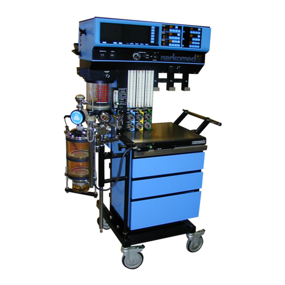
FOUR-GAS SELECTOR SWITCH (OPTIONAL) VAPORIZERS (OPTIONAL) MANUAL SPHYGMOMANOMETER FLOWMETER GAUGE (OPTIONAL) BANK VENTILATOR BELLOWS AUXILIARY OXYGEN FLOWMETER (OPTIONAL) FLUSH BUTTON BREATHING SYSTEM SENSOR INTERFACE PANEL FRESHGAS MAIN SWITCH COMMON PANEL OUTLET OP30001 Figure 1 NARKOMED 3 Anesthesia System, Front View... - Page 10 In trend, bargraph and data displays. addition, the anesthesia machine monitors all key anesthesia system functions (e.g., The NARKOMED 3 can be optionally oxygen supply pressure, O O flow ratio, equipped with an absorber system and/or backup battery status).
-
Page 11: Moving The Narkomed 3
RETURN TO CD-ROM TABLE OF CONTENTS MOVING THE NARKOMED 3 When moving the NARKOMED 3, use only The NARKOMED 3 is equipped with two the handles shown in Figure 3. DO NOT locking casters on the front of the machine. -
Page 12: Gas Delivery System
In addition to oxygen and nitrous oxide, attached supply hoses when reserve the NARKOMED 3 may be equipped with cylinders are in use. up to two additional gases. The additional gases may be air, oxygen-helium (O... - Page 13 RETURN TO CD-ROM TABLE OF CONTENTS GAS DELIVERY SYSTEM (continued) Gas Cylinder Yokes The NARKOMED 3 can be equipped with prevent cylinder from being a maximum of two oxygen and two nitrous improperly connected, the yokes are oxide cylinder hanger yokes (Figure 4). An...
- Page 14 Cylinders NARKOMED 3 is provided with a cylinder attached to the hanger yokes must contain pressure gauge, located at the bottom of gas at the recommended pressures outlined the flowmeter panel on the front of the in the table below.
- Page 15 RETURN TO CD-ROM TABLE OF CONTENTS GAS DELIVERY SYSTEM (continued) FINE FLOW TUBE (ml/min), O 1000 1000 COARSE FLOW TUBE (l/min), O INDICATOR FLOATS, O FLOWMETER KNOB GUARD PRECISION FLOW CONTROL KNOB, O PIPELINE PIPELINE PIPELINE PRESSURE GAUGE, O CYLINDER PRESSURE GAUGE, O CYLINDER...
- Page 16 RETURN TO CD-ROM TABLE OF CONTENTS GAS DELIVERY SYSTEM (continued) COARSE FLOW TUBE (l/min), N 1000 1000 1000 FINE FLOW TUBE (ml/min), N INDICATOR FLOATS, N FLOWMETER KNOB GUARD PRECISION FLOW CONTROL VALVE, N PIPELINE PRESSURE PIPELINE PIPELINE PIPELINE GAUGE, N CYLINDER PRESSURE GAUGE, N CYLINDER...
- Page 17 RETURN TO CD-ROM TABLE OF CONTENTS GAS DELIVERY SYSTEM (continued) FINE FLOW TUBE (ml/min), O 1000 1000 COARSE FLOW TUBE (l/min), O INDICATOR FLOATS, O FLOWMETER KNOB GUARD PRECISION FLOW CONTROL KNOB, O PIPELINE PRESSURE GAUGE, O PIPELINE PIPELINE PIPELINE CYLINDER CYLINDER CYLINDER...
- Page 18 7). If the anesthesia machine is equipped position). with air, a pipeline pressure gauge for air is also included. Carbon dioxide and oxygen-helium mixture supplies for NARKOMED 3 machines are provided exclusively from cylinders. Thus, these gases do not require pipeline pressure gauges.
- Page 19 RETURN TO CD-ROM TABLE OF CONTENTS GAS DELIVERY SYSTEM (continued) Oxygen Supply Pressure Failure Flow Control Valves Protection Device (OFPD) A needle valve is located below the fine The oxygen failure protection device flowmeter tube for each specific gas. This (OFPD) is a pneumatically operated valve valve is used to adjust the flow of gas located...
- Page 20 RETURN TO CD-ROM TABLE OF CONTENTS GAS DELIVERY SYSTEM (continued) Flowmeters Flowmeters, located immediately above Oxygen, nitrous oxide and air flowmeters their corresponding flow control valves are equipped with floats, half chrome- (Figures 5, 6 & 7), display the flow rate of plated and half colored red, to indicate free each gas delivered for the fresh gas movement through rotation.
- Page 21 If required for low-flow anesthesia, the They are calibrated as shown in the table NARKOMED 3 can be optionally modified below. to eliminate the minimum oxygen flow feature. label...
- Page 22 RETURN TO CD-ROM TABLE OF CONTENTS GAS DELIVERY SYSTEM (continued) Oxygen Ratio Monitor/Controller (ORMC) The ORMC is a pneumatic O Due to rebreathing of previously exhaled interlock system designed to maintain a gas in a circle system, lower fresh gas fresh gas oxygen concentration of at least flows require...
- Page 23 RETURN TO CD-ROM TABLE OF CONTENTS GAS DELIVERY SYSTEM (continued) Gas Selector Switch (Optional) Setting the gas selector switch to the "O & The "ALL GASES" position of the gas O" position permits oxygen and nitrous selector switch permits the additional oxide flows to the appropriate flowmeter gases to flow to their respective flowmeter controls.
- Page 24 RETURN TO CD-ROM TABLE OF CONTENTS GAS DELIVERY SYSTEM (continued) Vaporizers (Optional) The NARKOMED 3 can be equipped with A calibrated concentration of vaporized up to three Vapor 19.1 vaporizers for the anesthetic is produced by adjusting the administration of liquid anesthetics. The top-mounted handwheel of the selected vaporizers (Figures 9 &...
- Page 25 RETURN TO CD-ROM TABLE OF CONTENTS GAS DELIVERY SYSTEM (continued) lever interlock system, WARNING: Only one vaporizer can be incorporated into the vaporizer bank, activated at a time. If the exclusion system prevents more than one vaporizer from permits simultaneous activation of more being activated and requires all unused than one vaporizer, DO NOT use the vaporizers to be locked in their zero...
- Page 26 The valve, when actuated, delivers an unmetered oxygen flow of approximately The 15 mm male fitting on the fresh gas 55 l/min directly to the NARKOMED 3’s hose is unique to North American Dräger fresh gas common outlet. The oxygen flush...
- Page 27 Suction System (Optional) patient breathing system. It is located to the left of the oxygen flush button on the The NARKOMED 3 can be configured with front of the anesthesia machine. The outlet internal vacuum piping for a suction incorporates a dual fitting that allows use drainage assembly.
-
Page 28: Av-E Anesthesia Ventilator
RETURN TO CD-ROM TABLE OF CONTENTS AV-E ANESTHESIA VENTILATOR The anesthesia ventilator (Figure 13) is between 40 and 60 psi. The ventilator will volume-preset and time-cycled. It has a not function if this pressure drops below 32 solid-state timer and independent controls. psi. - Page 29 RETURN TO CD-ROM TABLE OF CONTENTS AV-E ANESTHESIA VENTILATOR (continued) NOTE: anesthesia ventilator Smaller tidal volumes can be adjusted by designed for use with an NAD absorber setting the pointer below the 200 ml s y s t e m , w h i c h i n c o r p o r a t e s marking on the bellows chamber.
- Page 30 RETURN TO CD-ROM TABLE OF CONTENTS AV-E ANESTHESIA VENTILATOR (continued) Inspiratory Flow Control Ventilator Relief Valve The rotary knob marked "INSPIRATORY During automatic ventilation, FLOW" controls the flow rate of gas into manual/automatic selector valve isolates the bellows chamber, and the inspiratory the absorber’s APL (adjustable pressure flow rate of gas into the patient’s lungs.
-
Page 31: Power Supply System
RETURN TO CD-ROM TABLE OF CONTENTS POWER SUPPLY Power Supply The NARKOMED 3 is equipped with a 240 Volt Power Supply (Optional) central power supply for the ventilator, alarm system, and monitoring system. The The NARKOMED 3 can be equipped with power of each monitor is individually an optional 240 VAC power supply. - Page 32 AC power source. The alarm message "AC PWR FAIL" appears in the central alarm NOTE: If the NARKOMED 3 is left display. with its power cable not plugged into an active AC wall outlet for a period of A single-tone audible alarm sounds.
- Page 33 POWER SUPPLY (continued) Circuit Breakers EMI Filtering The electrical system includes three All power for the NARKOMED 3 is filtered magnetic circuit breakers to protect the for conducted electromagnetic interference various machine functions (primary AC by a low pass filter in the primary AC line.
-
Page 34: Main Switch Panel
RETURN TO CD-ROM TABLE OF CONTENTS MAIN SWITCH PANEL The main switch panel, located between Oxygen Supply Pressure Alarm the ventilator bellows and flowmeter bank, incorporates alarms to communicate the oxygen supply pressure alarm status of the gas delivery and power activates if the oxygen supply pressure supply systems. - Page 35 A steady, high-pitched audible alarm AC Power Failure Indicator activates if the NARKOMED 3 pneumatic circuitry is pressurized by the SYSTEM The yellow "AC POWER FAIL" LED signals POWER switch, but a malfunction in the AC power disruption.
-
Page 36: Monitoring System
RETURN TO CD-ROM TABLE OF CONTENTS MONITORING SYSTEM GENERAL DESCRIPTION BAROMED Breathing Pressure Monitor NARKOMED incorporates The BAROMED monitors breathing system standard, integral monitors: pressure at either the absorber or the Y-piece. The unit can display mean, peak, or positive BAROMED breathing pressure monitor end expiratory (PEEP) pressure in cm H MED oxygen analyzer... - Page 37 ET AGENT PEAK AGENT ALARMS ALARMS INSP AGENT SELECT PEEP mmHg DISABLE cm H2O DISABLE ALARMS BREATHING PRESSURE ALARMS APNEA APNEA ET CO PRES HI ET CO SUB ATM AGENT HI CTNG PRES OP30016 Figure 15 Figure 15 NARKOMED 3 Monitors...
- Page 38 The gauge accuracy is ±1 % of full scale An aneroid manual sphygmomanometer can within a range of 75-225 mm Hg and ±3% of be mounted on the NARKOMED 3 (see Figure full scale outside of this range. 16).
- Page 39 RETURN TO CD-ROM TABLE OF CONTENTS MONITORING SYSTEM (continued) Then, watch the gauge reading for 10 For example, to exclude the cuff inflation seconds; the gauge indication shall not bulb, pinch the cuff inflation hose after decrease more than 10 mm Hg within this inflating the cuff to 250 mm Hg.
- Page 40 A panel of four sensor connections is provided An optional boom arm can be mounted on the on the lower left side of the NARKOMED 3 left side of the monitoring bank. Patient (Figure 17). These connections pertain to the...
- Page 41 RETURN TO CD-ROM TABLE OF CONTENTS MONITORING SYSTEM (continued) O2SATMED SENSOR INTERFACE MULTISPEC SAMPLE-LINE OXIMETER INTERFACE SENSOR SAMPLE SPHYGMOMED CUFF INTERFACE BP CUFF MANUAL BP CUFF SPHYGMOMANOMETER BP GAUGE INTERFACE OP30018 O2MED SENSOR INTERFACE SPIROMED SENSOR OXYGEN INTERFACE SENSOR VOLUME SENSOR BAROMED PILOT BREATHING...
- Page 42 Five Port Serial Interface (Optional) WARNING: Requires immediate action. Warning conditions are annunciated by a The NARKOMED 3 may be equipped with a continuously repeating tone pattern and a Five Port Serial...
- Page 43 (or more) RS-232 ASCII printer for also selected using the configure screen. When data logging. The configure screen is used to using a printer with the NARKOMED 3, a select the printer protocol for the desired port line of data is printed once every print...
- Page 44 RETURN TO CD-ROM TABLE OF CONTENTS MONITORING SYSTEM (continued) Central Monitoring Display The central monitoring display organizes the All continuous audible alarms are presentation of measured variables and alarm silenced for a period of 120 seconds. conditions. The display’s two screens make up (During this period, any occurrence of a the left portion of the upper housing of the new alarm will produce a non-repeating...
- Page 45 RETURN TO CD-ROM TABLE OF CONTENTS MONITORING SYSTEM (continued) Each monitor automatically selects If a monitor fault condition (such as a commonly used alarm limits and display disconnected sensor) is corrected, a formerly selections. The operator can, at any time, disabled alarm will become enabled upon override these default settings with each correction of the fault condition.
- Page 46 RETURN TO CD-ROM TABLE OF CONTENTS MONITORING SYSTEM (continued) Each type of alarm message produces a different Real-Time Pulse Bargraph and sound pattern: Carbon Dioxide Trace Warning: A continuously repeating tone The central alarm display incorporates two real- pattern. time displays for a quick, qualitative assessment of patient condition.
- Page 47 RETURN TO CD-ROM TABLE OF CONTENTS MONITORING SYSTEM (continued) Real-Time Clock The central alarm display also includes a real- The occurrence of a new alarm during a silence time clock. This unlabeled digital display is period results in a non-repeating tone pattern located beneath the Advisory display area (see corresponding to the alarm.
- Page 48 RETURN TO CD-ROM TABLE OF CONTENTS MONITORING SYSTEM (continued) System Control Keypad Oriented vertically and to the right of the display screens, the system control keypad calls up a series of displays and menus on the two display screens. PULSE 12.5 ETCO DI A S...
- Page 49 RETURN TO CD-ROM TABLE OF CONTENTS MONITORING SYSTEM (continued) Checkout Display (Refer to Figure 23) Selecting the "SpO2/NIBP INTERLOCK" item on the menu allows the operator to coordinate Pressing the "CHECKOUT" key calls up the SATMED’s alarms with checkout display on the left-hand screen. This SPHYGMOMED’s cuff inflation for those selection provides a text display of pre-use instances where the O...
- Page 50 Switching the NARKOMED 3 to standby physiologic and system parameters. When automatically disables the neonatal mode.
- Page 51 "NIBP tuation of the "LOG DATA" key after the PULSE." The Data Display waits approximately NARKOMED 3 has been turned on, a "DATA one minute before switching to the SPHYG- LOG" label appears above the left-hand selection MOMED pulse rate measurement.
- Page 52 RETURN TO CD-ROM TABLE OF CONTENTS MONITORING SYSTEM (continued) Pressing this selection key then displays the pre- Saturation Bargraph Display viously logged data as it appeared at the actuation of the "LOG DATA" key. Each "logged" The oxygen saturation bargraph displays the screen is labeled with an Event number (up to percent arterial hemoglobin saturation as Event 99) and the time at which it had been...
- Page 53 RETURN TO CD-ROM TABLE OF CONTENTS MONITORING SYSTEM (continued) ALARM LIMIT INSTANTANEOUS CO INSTANTANEOUS INDICATOR CUFF PRESSURE PARTIAL PRESSURE SYST PULSE DIAS MM HG VOL % /MIN MM HG 2:20 ENTER NIBP SAMPLE AGE MEAN BLOOD IN MINUTES AND PRESSURE OP30027 SECONDS (MAP)
- Page 54 RETURN TO CD-ROM TABLE OF CONTENTS MONITORING SYSTEM (continued) TREND MONITOR Trend Display Screen Pressing the "TREND" key invokes the Trend The Trend Display screen is invoked when the monitor’s display screen (Figure 27). The Trend "TREND" key is pressed. Two trend graphs, monitor is activated on power-up and provides each representing a specific measurement’s trend up to 8 hours of trend history for up to 17...
- Page 55 RETURN TO CD-ROM TABLE OF CONTENTS MONITORING SYSTEM (continued) The box in the bottom right corner of the Trend To select a specific configuration, the operator display screen contains labels for the remaining must: four Trend Monitor screens. By using the soft key beneath the labels, the operator can select a 1.
- Page 56 RETURN TO CD-ROM TABLE OF CONTENTS MONITORING SYSTEM (continued) Trend Graph Selection During the recovery phase of an operation, the top of the envelope area represents expired Measurement display selections for the top and agent, while the bottom represents inspired bottom trend graphs appear in the two left agent.
- Page 57 RETURN TO CD-ROM TABLE OF CONTENTS MONITORING SYSTEM (continued) Selectable Trend Grid To aid in the interpretation of a trend graph, the automatically shifts the data to provide a 5- Trend Monitor features a selectable trend grid. minute history and space for the next 5 minutes of trend data.
- Page 58 RETURN TO CD-ROM TABLE OF CONTENTS MONITORING SYSTEM (continued) The time of occurrence, as well as seven Configuration selections for the Set Up Data Log measurements, are displayed for each event. screen are implemented in the same style as the Pressing the highlighted "PAGE"...
- Page 59 RETURN TO CD-ROM TABLE OF CONTENTS MONITORING SYSTEM (continued) REAL-TIME TRACE MONITOR Pressing the "TRACE" key calls up a real-time Successive keystrokes will toggle the sweep trace display on the right-hand display screen speed selection between "SLOW" (16 seconds) (Figure 31). The display is capable of presenting and "FAST"...
- Page 60 RETURN TO CD-ROM TABLE OF CONTENTS MONITORING SYSTEM (continued) CURRENT GAP IN TRACE REPRESENTS PREVIOUS SWEEP DIVISION BETWEEN CURRENT SWEEP SWEEP AND PREVIOUS SWEEP BREATHING CO 2 SLOW SWEEP PRESSURE FAST FREEZE ENTER ENTER UPPER TRACE LOWER TRACE SWEEP SPEED WAVEFORM SELECTION KEY SELECTION KEY...
-
Page 61: Narkomed 3 Setup & Installation
RETURN TO CD-ROM TABLE OF CONTENTS NARKOMED 3 SETUP & INSTALLATION Initial Setup Initial setup of a NARKOMED 3 anesthesia Connect the gas fitting on the supply machine shall be by or under the direct hose to the corresponding gas fitting... - Page 62 RETURN TO CD-ROM TABLE OF CONTENTS NARKOMED 3 SETUP & INSTALLATION (continued) YELLOW BLACK & WHITE CHECKERED AIR DISS GAS FITTING WHITE GREEN BLUE DISS GAS FITTING BLUE O DISS GAS FITTING VACUUM DISS VACUUM DISS FITTING FITTING YELLOW OP10092...
- Page 63 RETURN TO CD-ROM TABLE OF CONTENTS NARKOMED 3 SETUP & INSTALLATION (continued) Cylinder Connections The NARKOMED 3 is equipped with ANSI Insert the head of a gas cylinder with standard pin-indexed hanger yokes for E-size matching gas color code into the yoke reserve gas cylinders.
- Page 64 "STANDBY" position. NARKOMED 3 to "STANDBY." Electrical Power Connection The NARKOMED 3 is equipped with a power cable with a hospital grade plug for the 117 VAC primary electrical power or with a power cable with a hospital grade plug for the optional 240 VAC primary electrical power.
- Page 65 IBM PC AT (or compatible) with a An optional Five Port Serial Interface allows user-supplied device. various external devices to communicate with the NARKOMED 3. A typical method of Attach the 9-pin connector to the connection follows: appropriate port on the rear underside anesthesia machine’s...
- Page 66 PRESSURE" (Fig. 35). If the shorter Pull the fresh gas locking bar, located pilot line is used, it reads the pressure on the front of the NARKOMED 3, at the absorber top dome gas pipe by out to its extended position (Figs. 11 means of a quick-connect fitting.
- Page 67 RETURN TO CD-ROM TABLE OF CONTENTS NARKOMED 3 SETUP & INSTALLATION (continued) TO OXYGEN ANALYZER EXPIRATORY TO RESPIRATORY INTERFACE PANEL VALVE W/22MM VOLUME MONITOR BREATHING INTERFACE PANEL OXYGEN ANALYZER HOSE SENSOR TERMINAL 19MM SCAVENGER RESPIRATORY HOSE VOLUME MONITOR APL VALVE...
- Page 68 (marked "SCAVENGER HOSE") on the rear of the absorber Installation of an open reservoir scavenger pole. system (Fig. 35) on the NARKOMED 3 is as follows: Verify the proper functioning of the scavenger system. Check for excessive NOTE: Two different types of scavenger PEEP or NEEP during ventilation.
- Page 69 RETURN TO CD-ROM TABLE OF CONTENTS NARKOMED 3 SETUP & INSTALLATION (continued) VENTILATOR VENTILATOR PRESSURE BELLOWS W/22MM 22MM OXYGEN SENSING PORT VENTILATOR BREATHING QUICK-CONNECT ANALYZER HOSE TERMINAL HOSE INTERFACE FITTING PANEL RELIEF VALVE W/19MM OXYGEN SCAVENGER ANALYZER HOSE TERMINAL SENSOR...
-
Page 70: Pre-Use Checkout Procedure
RETURN TO CD-ROM TABLE OF CONTENTS PRE-USE CHECKOUT PROCEDURE Prior to operating the NARKOMED 3, the fol- Verify that the correct gases are lowing checkout procedures shall be performed supplied to the anesthesia machine to ensure that the machine is ready for use. If inlets. - Page 71 RETURN TO CD-ROM TABLE OF CONTENTS PRE-USE CHECKOUT PROCEDURE (continued) D. If equipped with dual oxygen A. Verify the existence of 2 index pins reserve cylinder yokes, press the flush in the yoke, and mount cylinder. button again to empty the piping. Then, repeat the above steps for the B.
- Page 72 RETURN TO CD-ROM TABLE OF CONTENTS PRE-USE CHECKOUT PROCEDURE (continued) *16. Check the function of the flowmeters: The ORMC shall maintain a fresh gas Attach pipeline supplies oxygen/nitrous oxide flow ratio of at disconnected). Adjust the flow control least 25 (±4)%. At low flows the ORMC knob for each gas and verify the proper will maintain a fresh gas oxygen operation...
- Page 73 RETURN TO CD-ROM TABLE OF CONTENTS PRE-USE CHECKOUT PROCEDURE (continued) A. The fresh gas hose of the J. A 19 mm scavenger hose shall be breathing system intended for connected between the bottom of use shall be connected to the fresh absorber pole scavenger.
- Page 74 RETURN TO CD-ROM TABLE OF CONTENTS PRE-USE CHECKOUT PROCEDURE (continued) To perform the test: To check the APL valve’s flow resistance: A. First close all flow control valves on the anesthesia machine. A. First set the manual/automatic selector valve to the "BAG" position. B.
- Page 75 RETURN TO CD-ROM TABLE OF CONTENTS PRE-USE CHECKOUT PROCEDURE (continued) B. With the scavenger needle valve *29. Test the ventilator: open enough to allow flow through the scavenger and all flow control valves A. Check for proper pressure and flow on the anesthesia machine closed, at the Y-piece during the inspiratory occlude the absorber breathing bag...
- Page 76 Check the alarm limit settings: The connected. Check the final positions of NARKOMED 3 automatically sets all controls, specifically the flow monitor alarm limits to a default control valves, vaporizer controls, configuration when the System Power manual/automatic...
-
Page 77: Cleaning And Sterilization
Clean painted, plated, and plastic surfaces of adjustment lock ring on the ventilator the NARKOMED 3 with a soft cloth relief valve dome. DO NOT attempt to moistened with an aqueous germicidal loosen the knurled relief valve ring cleanser. - Page 78 RETURN TO CD-ROM TABLE OF CONTENTS CLEANING & STERILIZATION (continued) Rubber Goods Manual Sphygmomanometer Follow hospital procedures and sterilizer t y p i c a l u s a g e , t h e M a n u a l manufacturer’s instructions Sphygmomanometer will not require any...
-
Page 79: Precautions (Maintenance & Use)
Dräger. The ORMC maintains a nominal O fresh gas flow ratio of at least 25 (±4) %. The NARKOMED 3 is designed for use with Hypoxic fresh gas mixtures may be delivered non-flammable anesthetic agents. Flammable is used as an additional gas. - Page 80 Do not force the oxygen flow control knob over the end stop of the The NARKOMED 3 shall only be used in con- valve. Forcing the knob could damage the junction with a functioning oxygen analyzer delicate valve seat.
- Page 81 RETURN TO CD-ROM TABLE OF CONTENTS PRECAUTIONS (MAINTENANCE & USE) (continued) Communications may be temporarily affected To ensure proper direction of gas flow during by electromagnetic interference due to the use inspiratory expiratory phases, of certain electrosurgical equipment. following must occur: (1) the inspiratory valve must provide free gas passage from the Regardless of the indications of any alarm or breathing system to the patient and not allow...
-
Page 82: Spare And Replacement Parts
Data Cable (DB9/DB25/10 ft.) for link to printer ......4110568 Narkomed 3 Operator’s Instruction Manual ....... . . 4108980 Vitalink Technical Reference Manual . - Page 83 RETURN TO CD-ROM TABLE OF CONTENTS SPARE & REPLACEMENT PARTS (continued) Description Part Number Oxygen Analyzer Accessories Sensor Capsule ..........6803290 Sensor Housing &...
-
Page 84: Appendix 1: Narkomed 3 Specifications
RETURN TO CD-ROM TABLE OF CONTENTS APPENDIX 1: NARKOMED 3 SPECIFICATIONS GENERAL Maximum Dimensions (W x H x D) ..... . 31 3/4 x 64 1/2 x 27 1/4 inches Weight (approximate) . - Page 85 RETURN TO CD-ROM TABLE OF CONTENTS APPENDIX 1: NARKOMED 3 SPECIFICATIONS (continued) ELECTRICAL (cont.) Circuit Breakers Primary AC power input (machine) ........5.0 amps AC Convenience receptacles (117 VAC power supply only) .
- Page 86 RETURN TO CD-ROM TABLE OF CONTENTS APPENDIX 1: NARKOMED 3 SPECIFICATIONS (continued) GAS DELIVERY SYSTEM (cont.) Cylinder pressures Recommended maximum pressures , Air ..........2200 psi (15,150 kPa) O .
- Page 87 RETURN TO CD-ROM TABLE OF CONTENTS APPENDIX 1: NARKOMED 3 SPECIFICATIONS (continued) GAS DELIVERY SYSTEM (cont.) Isoflurane: Adjustment range ......... . . 0.2 - 5 vol% Accuracy .
- Page 88 RETURN TO CD-ROM TABLE OF CONTENTS APPENDIX 1: NARKOMED 3 SPECIFICATIONS (continued) SPIROMETER Minute Volume: Range ........... 0.1 to 99.9 l Resolution .
- Page 89 RETURN TO CD-ROM TABLE OF CONTENTS APPENDIX 1: NARKOMED 3 SPECIFICATIONS (continued) MULTISPEC (continued) Halothane Measurement Range ........0 to 8.5 volume % Halothane Resolution .
- Page 90 RETURN TO CD-ROM TABLE OF CONTENTS APPENDIX 1: NARKOMED 3 SPECIFICATIONS (continued) SATMED Monitor display range ..........0 to 100% Resolution .
- Page 91 RETURN TO CD-ROM TABLE OF CONTENTS APPENDIX 1: NARKOMED 3 SPECIFICATIONS (continued) MANUAL SPHYGMOMANOMETER (Optional) Type ............Aneroid Range .
-
Page 92: Appendix 2: Narkomed 3 Alarm Messages
RETURN TO CD-ROM TABLE OF CONTENTS APPENDIX 2: NARKOMED 3 ALARM MESSAGES CLASS ALARM MESSAGE CONDITION AUDIO % OXYGEN LOW < low limit setting CONT APNEA - PRES Apnea for 30 seconds CONT APNEA - VOL Apnea for 30 seconds... - Page 93 RETURN TO CD-ROM TABLE OF CONTENTS APPENDIX 2: NARKOMED 3 ALARM MESSAGES (continued) CLASS ALARM MESSAGE CONDITION AUDIO APNEA - VOL Apnea for 15 seconds INTERMIT APNEA - CO2 Apnea for 15 seconds INTERMIT CONTNG PRES Pressure > threshold limit for 15...
- Page 94 RETURN TO CD-ROM TABLE OF CONTENTS APPENDIX 2: NARKOMED 3 ALARM MESSAGES (continued) CLASS ALARM MESSAGE CONDITION AUDIO % ENF LOW Enflurane % < low limit INTERMIT % ISO LOW Isoflurane % < low limit INTERMIT AGT DETECTED Gas monitor agent detected, none...
- Page 95 RETURN TO CD-ROM TABLE OF CONTENTS APPENDIX 2: NARKOMED 3 ALARM MESSAGES (continued) CLASS ALARM MESSAGE CONDITION AUDIO CAL ERR Bad calibration data NONE THRESHOLD LO Threshold pressure alarm limit set NONE > 6 or > 8 cm H O from sensed peak PEEP ≥...
- Page 96 RETURN TO CD-ROM TABLE OF CONTENTS APPENDIX 2: NARKOMED 3 ALARM MESSAGES (continued) CLASS ALARM MESSAGE CONDITION AUDIO CO2 LINE BLK Gas monitor sample line blocked NONE CO2/AGT ERR Gas monitor internal failure NONE AGT NOT SEL Gas monitor agent not selected...
- Page 97 RETURN TO CD-ROM TABLE OF CONTENTS APPENDIX 2: NARKOMED 3 ALARM MESSAGES (continued) CLASS ALARM MESSAGE CONDITION AUDIO OXIMETER ERR Self-diagnostic NONE SPHYGMOM ERR Self-diagnostic NONE SPIROMED ERR Self-diagnostic NONE EXT COMM ERR Self-diagnostic NONE PORT A ERR Communications error...
-
Page 98: Appendix 3: Narkomed 3 Troubleshooting Guide
Inspiratory flow control setting Increase inspiratory flow on ventilator too low control setting Frequency too high Decrease frequency For troubleshooting assistance for the monitors included in the NARKOMED 3, see the Troubleshooting sections of the Operator’s Manuals for the individual monitors. -
Page 99: Appendix 4: Visual Symbols
RETURN TO CD-ROM TABLE OF CONTENTS APPENDIX 4: VISUAL SYMBOLS Visual symbols are used on N.A.D. products to provide quick and easy recognition of the product’s function. A list of symbols and their descriptions is given below. Oxygen Concentration Carbon Dioxide Concentration Gas Concentration Breathing Pressure Breathing Volume... -
Page 100: Index
RETURN TO CD-ROM TABLE OF CONTENTS INDEX Absorbent, handling ... . . 65 Color coding ....4 Absorber system installation . - Page 101 RETURN TO CD-ROM TABLE OF CONTENTS INDEX (continued) Inspiratory flow control ... 22 PEEP valve ....22 Inspiratory/Expiratory phase time...
- Page 102 RETURN TO CD-ROM TABLE OF CONTENTS INDEX (continued) Vaporizers Warnings ..... . . 2 description ....16 installation .
- Page 103 RETURN TO CD-ROM TABLE OF CONTENTS...
- Page 104 Telford, Pennsylvania 18969 Telephone: (215) 721-5400 Telefax: (215) 721-9561 (SALES) (215) 723-5935 (SERVICE) Part Numbers: 4108980 (NARKOMED 3 Operator’s Instruction Manual) 4108836 (NARKOMED 3 Anesthesia System) 4109500 (NARKOMED 3 Anesthesia System - Canada) Rev: Date: May 22, 1992 © N.A.D. Inc. 1992...
Need help?
Do you have a question about the NARKOMED 3 and is the answer not in the manual?
Questions and answers