Sign In
Upload
Manuals
Brands
Omron Manuals
Computer Hardware
NX102-11 Series
Omron NX102-11 Series Manuals
Manuals and User Guides for Omron NX102-11 Series. We have
4
Omron NX102-11 Series manuals available for free PDF download: User Manual
Omron NX102-11 Series User Manual (578 pages)
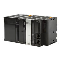
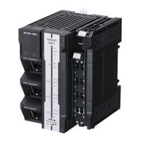
Machine Automation Controller, CPU Unit Built-in EtherNet/IP Port
Brand:
Omron
| Category:
Controller
| Size: 13.97 MB
Table of Contents
Intended Audience
3
Applicable Products
3
Relevant Manuals
4
Manual Structure
6
Page Structure
6
Special Information
7
Precaution on Terminology
7
Sections in this Manual
9
Table of Contents
10
Terms and Conditions Agreement
17
Warranty, Limitations of Liability
17
Application Considerations
18
Disclaimers
18
Safety Precautions
20
Precautions for Safe Use
21
Precautions for Correct Use
22
Regulations and Standards
23
Versions
24
Checking Versions
24
Unit Versions of CPU Units and Sysmac Studio Versions
28
Unit Versions of CPU Units and Peripheral Tool Versions
28
Related Manuals
29
Revision History
32
Introduction
35
Ethernet/Ip Features
36
Features of Built-In Ethernet/Ip Port on NJ/NX-Series CPU Units
36
Introduction
36
System Configuration and Configuration Devices
39
Devices Required to Construct a Network
39
Support Software Required to Construct a Network
40
Built-In Ethernet/Ip Port
42
Specifications
42
Part Names and Functions
46
Introduction to Communications Services
53
CIP (Common Industrial Protocol) Communications Services
53
IP Routing
55
Packet Filter
56
BOOTP Client
57
FTP Server
57
FTP Client
58
Automatic Clock Adjustment
58
Socket Service
59
Specifying Host Names
60
SNMP Agent
60
TCP/UDP Message Service
61
Ethernet/Ip Communications Procedures
62
Selecting the Network Devices
66
Recommended Network Devices
66
Ethernet Switch Types
67
Ethernet Switch Functions
67
Precautions for Ethernet Switch Selection
68
Network Installation
71
Basic Installation Precautions
71
Recommended Network Devices
71
Precautions When Laying Twisted-Pair Cable
71
Precautions When Installing and Connecting Ethernet Switches
75
Connecting to the Network
77
Ethernet Connectors
77
Connecting the Cable
77
System-Defined Variables Related to the Built-In Ethernet/Ip Port
79
System-Defined Variables
81
Specifications for Individual System-Defined Variables
114
Determining IP Addresses
141
IP Addresses
142
IP Address Configuration
142
Allocating IP Addresses
142
Subnet Mask
142
Cidr
143
Built-In Ethernet/Ip Port IP Address Settings
145
Determining IP Addresses
145
Setting IP Addresses
145
Online Connection
148
Checking the Current IP Address
151
Private and Global Addresses
152
Using a Private Address for the Built-In Ethernet/Ip Port
153
Using a Global Address for the Built-In Ethernet/Ip Port
154
Sysmac Studio Settings for the Built-In Ethernet/Ip Port
155
TCP/IP Settings Display
156
LINK Settings Display
162
FTP Settings Display
163
NTP Settings Display
164
SNMP Settings Display
166
SNMP Trap Settings Display
168
PING Command
172
Using the PING Command
172
Host Computer Operation
172
Introduction to Tag Data Links
176
Tag Data Links
176
Data Link Data Areas
177
Tag Data Link Functions and Specifications
180
Overview of Operation
181
Starting and Stopping Tag Data Links
183
Controller Status
184
Concurrency of Tag Data Link Data
186
Controller Status
186
Setting Tag Data Links
193
Starting the Network Configurator
193
Tag Data Link Setting Procedure
195
Registering Devices
195
Creating Tags and Tag Sets
197
Connection Settings
210
Creating Connections Using the Wizard
220
Creating Connections by Dragging and Dropping Devices
223
Connecting the Network Configurator to the Network
226
Downloading Tag Data Link Parameters
232
Uploading Tag Data Link Parameters
235
Verifying Tag Data Link Parameters
238
Starting and Stopping Tag Data Links
242
Clearing the Device Parameters
245
Saving the Network Configuration File
247
Reading a Network Configuration File
248
Checking Connections
250
Changing Devices
251
Displaying Device Status
252
Ladder Programming for Tag Data Links
254
Status Flags Related to Tag Data Links
258
Tag Data Links with Other Models
260
CIP Message Communications
263
Overview of the CIP Message Communications Service
265
Message Communications Service Specifications
265
CIP Message Communications Client Function
266
Overview
266
CIP Communications Instructions
266
Using CIP Communications Instructions
267
Route Path
268
Route Path
269
Request Path (IOI)
278
Service Data and Response Data
282
Sample Programming for CIP Connectionless (UCMM) Message Communications
284
Sample Programming for CIP Connection (Class 3) Message Communications
289
Sample Programming for CIP Connection (Class 3) Message Com- Munications
289
Operation Timing
296
Response Codes
297
CIP Communication Server Function
301
CIP Message Structure for Accessing CIP Objects
301
CIP Message Structure for Accessing Variables
302
Specifying Request Path
303
Examples of CIP Object Specifications
303
Examples of Variable Specifications
304
Logical Segment
304
Data Segment
304
Specifying Variable Names in Request Paths
305
CIP Object Services
309
CIP Objects Sent to the Built-In Ethernet/Ip Port
309
Identity Object (Class ID: 01 Hex)
309
NX Configuration Object (Class ID: 74 Hex)
312
TCP/IP Interface Object (Class ID: F5 Hex)
334
Ethernet Link Object (Class ID: F6 Hex)
337
Controller Object (Class ID: C4 Hex)
343
Read and Write Services for Variables
345
Read Service for Variables
345
Write Service for Variables
346
Variable Data Types
349
Data Type Codes
349
Common Format
349
Elementary Data Types
350
Derived Data Types
351
Socket Service
355
Basic Knowledge on Socket Communications
356
Sockets
356
Port Numbers for Socket Services
356
Basic Knowledge on Protocols
357
Differences between TCP and UDP
357
Fragmenting of Send Data
358
Data Receive Processing
360
Broadcasting
363
Overview of Built-In Ethernet/Ip Port Socket Services
364
Overview
364
Procedure
364
Settings Required for the Socket Services
365
Socket Service Instructions
366
Details on Using the Socket Services
367
Using the Socket Services
367
Procedure to Use Socket Services
367
Timing Chart for Output Variables Used in Communications
369
UDP Sample Programming
370
TCP Sample Programming
376
Precautions in Using Socket Services
383
Precautions for UDP and TCP Socket Services
383
Precautions for UDP Socket Services
383
Precautions for TCP Socket Services
383
TCP/UDP Message Service
385
Outline of TCP/UDP Message Service
385
Specifications of TCP/UDP Message Service
385
Settings Required for TCP/UDP Message Service
385
Command Format Specifications
385
Modbus TCP Master Function
389
Overview of Modbus TCP Master Function
390
10-2 Modbus TCP Master Function Details
391
Modbus TCP Instruction Type
391
Modbus TCP Instruction Function
391
Modbus TCP Master Function Procedure
392
11-1 Overview and Specifications
396
Overview
396
Specifications
396
11-2 FTP Server Function Details
398
Supported Files
398
Connecting to the FTP Server
398
11-3 Using the FTP Server Function
401
Procedure
401
List of Settings Required for the FTP Server Function
401
11-4 FTP Server Application Example
403
11-5 Using FTP Commands
405
Table of Commands
405
Using the Commands
405
11-6 Using SD Memory Card Operations
412
SD Memory Card Types
412
File Types
413
Initializing SD Memory Cards
414
Format of Variable Data
414
Application Example from a Host Computer
415
FTP Client
418
12-1 Using the FTP Client to Transfer Files
418
Transferring Files
418
Connectable FTP Servers
418
File Transfer Options
419
Other Functions
420
FTP Client Communications Instructions
421
Functions of the FTP Client Communications Instructions
421
Restrictions on the FTP Client Communications Instructions
424
12-3 FTP Client Application Example
425
Automatic Clock Adjustment
431
Overview
432
Specifications
432
Procedure to Use the Automatic Clock Adjustment Function
434
Procedure
434
Settings Required for Automatic Clock Adjustment
434
SNMP Agent
435
Overview
436
14-1 SNMP Agent
436
Specifications
437
SNMP Messages
437
MIB Specifications
438
14-2 Procedure to Use the SNMP Agent
455
Procedures
455
Settings Required for the SNMP Agent
455
15-1 Communications System
458
Tag Data Link Communications Method
458
Calculating the Number of Connections
460
Packet Interval (RPI) Accuracy
461
15-2 Adjusting the Communications Load
463
Checking Bandwidth Usage for Tag Data Links
464
Tag Data Link Bandwidth Usage and RPI
465
Adjusting Device Bandwidth Usage
466
Changing the RPI
467
RPI Setting Examples
472
15-3 I/O Response Time in Tag Data Links
478
Timing of Data Transmissions
478
Built-In Ethernet/Ip Port Data Processing Time
479
Relationship between Task Periods and Packet Intervals (Rpis)
481
Maximum Tag Data Link I/O Response Time
482
15-4 Message Service Transmission Delay
485
Troubleshooting
487
Overview of Troubleshooting
488
Checking Status with the Network Configurator
489
The Network Configurator's Device Monitor Function
489
Connection Status Codes and Troubleshooting
497
Appendices
505
Functional Comparison of Ethernet/Ip Ports on NJ/NX-Series CPU Units and Other Series
506
Use the Sysmac Studio to Set the Tag Data Links (Ethernet/Ip Connections
507
A-2-1 Overview of the Tag Data Links (Ethernet/Ip Connections) Settings with the Sysmac Studio
507
Overview of the Tag Data Links (Ethernet/Ip Connections) Settings with the Sysmac Studio
507
A-2-2 Procedure to Make the Ethernet/Ip Connection Settings with the Sysmac Studio
508
A-2-3 Ethernet/Ip Connection Settings
509
A-2-4 Making the Ethernet/Ip Connection Settings with the Sysmac Studio
513
A-2-5 Checking Communications Status with the Sysmac Studio and Troubleshooting
534
A-2-5 Checking Communications Status with the Sysmac Studio and Trou- Bleshooting
534
Troubleshooting
534
A-2-6 Troubleshooting
538
A-3 EDS File Management
543
A-3-1 Installing EDS Files
543
Installing EDS Files
543
A-3-2 Creating EDS Files
544
A-3-3 Deleting EDS Files
544
Saving EDS Files
545
Searching EDS Files
545
A-3-6 Displaying EDS File Properties
546
A-3-7 Creating EDS Index Files
546
Precautions for Using the Network Configurator on Windows XP, Windows Vis- Ta, or Windows 7 or Higher
547
Precautions for Using the Network Configurator on Windows XP, Windows Vista, or Windows 7 or Higher
547
Changing Windows Firewall Settings
547
A-5 Variable Memory Allocation Methods
550
A-5-1 Variable Memory Allocation Rules
550
A-5-2 Important Case Examples
559
Precautions When Accessing External Outputs in CPU Units
563
A-7 TCP State Transitions
564
Example of NX Unit Setting Using NX Configuration Object Service
566
A-8-1 Changing the Unit Operation Settings for Singe NX Unit
566
A-8-2 Changing the Unit Operation Settings for Multiple NX Units
567
A-8-3 Initializing the Unit Operation Settings for Singe NX Unit
567
A-9 Version Information
568
Advertisement
Omron NX102-11 Series User Manual (280 pages)
Machine Automation Controller, CPU Unit Built-in EtherCAT Port
Brand:
Omron
| Category:
Controller
| Size: 18.42 MB
Table of Contents
Intended Audience
3
Applicable Products
3
Relevant Manuals
5
Manual Structure
8
Page Structure
8
Special Information
9
Precaution on Terminology
9
Sections in this Manual
11
Table of Contents
12
Terms and Conditions Agreement
16
Warranty, Limitations of Liability
16
Application Considerations
17
Disclaimers
17
Safety Precautions
19
Precautions for Safe Use
20
Precautions for Correct Use
21
Regulations and Standards
22
Versions
23
Checking Versions
23
Unit Versions of CPU Units and Sysmac Studio Versions
27
Related Manuals
28
Revision History
31
Introduction
33
Introduction to Ethercat
34
Ethercat Features
34
Ethercat Communications
34
Ethercat Features for NJ/NX-Series CPU Units
35
System Configuration and Configuration Devices
36
System Configuration
36
Determining the Network Configuration
40
Specifications of Built-In Ethercat Port
42
Overview of Communications
44
Process Data Communications and SDO Communications
44
Other Functions
44
Ethercat Communications Procedure
47
Overview
47
Details
47
Section 2 Part Names and Slave Settings
52
Part Names and Functions
52
Built-In Ethercat Port Indicators
52
Windows Used in Sysmac Studio
54
Connecting the Sysmac Studio
57
Setting the Node Addresses of the Ethercat Slaves
59
Setting Node Address Using Hardware Switches
59
Setting the Node Address from the Sysmac Studio
60
Features of Sysmac Devices
62
Sysmac Devices
62
Sysmac Device Features
62
List of Sysmac Devices
64
Sysmac Device Features and Ethercat Masters
65
Section 3 Ethercat Communications
70
Ethercat Communications
70
Ethercat Communications Types and Settings
70
Coe (CAN Application Protocol over Ethercat)
70
Types of Communications
72
Types of Ethercat Variables
74
Settings Required for Ethercat Communications
75
Programming Ethercat Communications
76
State Transitions for Ethercat Communications
77
Self Diagnosis at Startup
77
Control States for Ethercat Communications
77
Ethercat Status in Relation to CPU Unit Status
79
Ethercat Network Wiring
81
Section 4 Ethercat Network Wiring
82
Supported Network Topologies
82
Line/Daisy Chain Topology
82
Branching Topology
82
Ring Topology
84
Precautions for Using Junction Slaves
90
Laying the Ethercat Network
92
Installation Precautions
92
Installing Ethercat Communications Cables
93
Connecting Communications Cables
96
Cable Connection Procedure
98
Setting up Ethercat Communications with the Sysmac Studio
99
Section 5 Setting up Ethercat Communications with the Sysmac
100
Overview of Network Configuration Information
100
Creating the Ethercat Network Configuration
101
Procedure to Create the Ethercat Network Configuration
101
Cable Redundancy Setting
103
Setting Ethercat Slave Variables and Axes
107
Registering Device Variables for All Ethercat Slaves
107
Axis Settings for Servo Drives and Encoder Input Slaves
111
Ethercat Master Parameter Settings
112
Ethercat Slave Parameter Settings
118
Changing the PDO Map Settings
121
Ethercat Slave Enable/Disable Settings
123
Comparing and Merging Ethercat Network Configurations
126
Introduction for Comparing and Merging Ethercat Network Configurations
126
Introduction for Comparing and Merging Ethercat Network Configu- Rations
126
Operation Procedure for Comparing and Merging Ethercat Network Configurations
126
When Compare and Merge with Actual Network Configuration Dialog Box Is Not Displayed
130
When Slaves on Actual Network Configuration Are Not Displayed
137
Automatically Creating the Network Configuration
138
Using the Sysmac Studio to Obtain Serial Numbers from the Actual Network Configuration
141
Using the Sysmac Studio to Obtain Serial Numbers from the Ac- Tual Network Configuration
141
Downloading the Network Configuration Information from the Sysmac Studio
143
Confirming Communications after Completing Ethercat Configuration and Settings5-47
145
Confirming Communications after Completing Ethercat Configuration and Settings
145
Process Data Communications (PDO Communications)
148
Allocated Variables for Process Data Communications
148
Process Data Communications Refresh Timing
149
Checking Validity of Process Data
152
System Response Time in Process Data Communications
157
I/O Operations for Major Fault Level Controller Errors and I/O Refreshing with Specified Values
161
SDO Communications
165
Ethercat Communications Instructions
165
Sample Programming
165
Execution Timing of SDO Communications
167
Minimum Message Response Time for SDO Communications
167
Instructions Used in Ethercat Communications
171
Ethercat Communications Instructions
171
System-Defined Variables that Are Related to the Built-In Ethercat Port
174
What Are System-Defined Variables
174
System-Defined Variables
174
Ethercat Master Function Module, Category Name
181
Example of Operations for Ethercat Communications
193
8-1 Example of Operations for Ethercat Communications
194
System Configuration Example
194
Wiring and Settings
194
Setting the Ethercat Network Configuration
194
Programming
196
Offline Debugging
197
Turning the Power on
197
Online Debugging
197
Downloading the Network Configuration Information and the User Program
197
Confirming the Start of Communications
197
Troubleshooting
199
Overview of Troubleshooting
200
How to Check for Errors
200
Errors Related to the Ethercat Master Function Module
200
Troubleshooting
201
Error Table
201
Error Descriptions
201
Resetting Errors
201
Diagnostic and Statistical Information
201
Identifying an Error Slave and Cause of Error
219
Precautions When Connecting or Disconnecting Slaves During Communications
223
Procedure for Connecting and Disconnecting Slaves During Communications
223
Procedure for Connecting and Disconnecting Slaves During Commu- Nications
223
Prohibition to Physically Disconnecting a Slave and Resetting an Error or Connecting a Slave at the same Time
223
Prohibition to Physically Disconnecting a Slave and Resetting an Er- Ror or Connecting a Slave at the same Time
223
Replacing Slaves During Communications
224
Introduction
224
Slave Replacement Methods
225
Backing up Settings
226
Restoring Settings
228
Replacement Procedure
230
Appendices
237
Ethercat Status in Relation to CPU Unit Status
238
A-1-1 When the Power Supply Is Turned on
238
When the Power Supply Is Turned on
238
A-1-2 CPU Unit Operating Modes
239
A-1-3 Controller Errors Other than Errors in the Built-In Ethercat Master
240
A-1-4 Others
241
A-1-5 When the Power Supply Is Turned off
242
A-2 Monitoring Packets
243
A-3 Multi-Vendor Environments
251
A-3-1 Ethercat Slave Information File (ESI Files
251
Ethercat Slave Information File (ESI Files
251
A-3-2 Connecting Slaves from Other Manufacturers to an OMRON Master
252
A-3-3 Installing ESI Files
252
Editing PDO Entry Tables
257
Settings for MDP-Compatible Slaves from Other Manufacturers
263
A-5 Terminology
267
Setting Transmission Delay Time by Actual Measurement
267
Version Information
267
A-5 Terminology
269
A-6-1 Functions that Were Added or Changed for each Unit Version
271
Differences between Project Unit Version Earlier than 1.40 and Project Unit Version 1.40 or Later
271
A-6 Version Information
271
A-6-2 Differences between Project Unit Version Earlier than 1.40 and Project Unit Version 1.40 or Later
271
Omron NX102-11 Series User Manual (68 pages)
Machine Automation Controller, NX-series CPU Unit, FINS Function
Brand:
Omron
| Category:
Computer Hardware
| Size: 0.97 MB
Table of Contents
Introduction
3
Intended Audience
3
Applicable Products
3
Relevant Manuals
4
Terms and Conditions Agreement
6
Warranty, Limitations of Liability
6
Application Considerations
7
Disclaimers
7
Manual Structure
9
Page Structure
9
Special Information
10
Precaution on Terminology
10
Table of Contents
11
Safety Precautions
13
Precautions for Safe Use
14
Precautions for Correct Use
15
Regulations and Standards
16
Versions
17
Checking Versions
17
Unit Versions of CPU Units and Sysmac Studio Versions
20
Related Manuals
21
Revision History
22
Sections in this Manual
23
Fins
25
Overview of FINS
26
Server Function of FINS
26
Client Function of FINS
26
Applicable CPU Units
27
System Configuration
28
Relationship between FINS Types and Units
29
Memory Used for CJ-Series Units
30
Setting for the Memory Used for CJ-Series Units
30
Compatible Memory for CJ-Series Units
30
Server Function
31
Overview of Server Function
32
FINS Commands Supported by NX-Series CPU Units
33
Setting of FINS Node Address of Built-In Ethernet/Ip Port
35
FINS Routing Table Setting
37
FINS Write Protection Function
38
FINS Command Execution Condition
39
Client Function
41
Overview of Client Function
42
FINS Communications Instructions
43
Send
44
Rcv
48
Sendcmd
54
Troubleshooting
59
A-1 Difference between CS/CJ-Series and NX-Series in FINS Routing
61
Appendices
61
Difference between CS/CJ-Series and NX-Series in FINS Routing
62
A-1-1 Communication When 0 Is Specified for the Destination Network Address
62
Operation of Routing Table During Clear All Memory Operation
64
Advertisement
Omron NX102-11 Series User Manual (66 pages)
Machine Automation Controller CPU Unit
Brand:
Omron
| Category:
Controller
| Size: 1.22 MB
Table of Contents
Intended Audience
3
Applicable Products
3
Relevant Manuals
4
Terms and Conditions Agreement
6
Warranty, Limitations of Liability
6
Application Considerations
7
Disclaimers
7
Manual Structure
9
Page Structure
9
Special Information
10
Precaution on Terminology
10
Sections in this Manual
11
Table of Contents
12
Safety Precautions
14
Precautions for Safe Use
15
Precautions for Correct Use
16
Regulations and Standards
17
Versions
18
Unit Versions of CPU Units and Sysmac Studio Versions
18
Related Manuals
19
Revision History
21
Fins
23
Overview of FINS
24
Server Function of FINS
24
Client Function of FINS
24
Applicable CPU Units
25
System Configuration
26
Relationship between FINS Types and Units
27
Memory Used for CJ-Series Units
28
Setting for the Memory Used for CJ-Series Units
28
Compatible Memory for CJ-Series Units
28
Server Function
29
Overview of Server Function
30
FINS Commands Supported by NX-Series CPU Units
31
Setting of FINS Node Address of Built-In Ethernet/Ip Port
33
FINS Routing Table Setting
35
FINS Write Protection Function
36
FINS Command Execution Condition
37
TCP/UDP Port Close Function
38
Client Function
39
Overview of Client Function
40
FINS Communications Instructions
41
Send
42
Rcv
46
Sendcmd
52
Troubleshooting
57
Appendices
59
Difference between CS/CJ-Series and NX-Series in FINS Routing
60
A-1-1 Communication When 0 Is Specified for the Destination Network Address
60
Operation of Routing Table During Clear All Memory Operation
62
Advertisement
Related Products
Omron NX102-12 Series
Omron NX102-10 Series
Omron NX102-90 Series
Omron NX1P2-11***1 Series
Omron NX1P2-10***1 Series
Omron NX1P2-90***1 Series
Omron New H7E Series
Omron New H7E N Series
Omron New H7ET
Omron NB HMI
Omron Categories
Blood Pressure Monitor
Controller
Accessories
Switch
Inverter
More Omron Manuals
Login
Sign In
OR
Sign in with Facebook
Sign in with Google
Upload manual
Upload from disk
Upload from URL