Omron NX102-90 Series Manuals
Manuals and User Guides for Omron NX102-90 Series. We have 6 Omron NX102-90 Series manuals available for free PDF download: User Manual, Instruction & Reference Manual
Omron NX102-90 Series User Manual (578 pages)
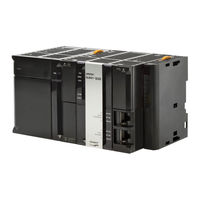
Machine Automation Controller, CPU Unit Built-in EtherNet/IP Port
Brand: Omron
|
Category: Controller
|
Size: 13 MB
Table of Contents
-
Disclaimers18
-
Versions24
-
Introduction35
-
Introduction36
-
IP Routing55
-
BOOTP Client57
-
FTP Server57
-
FTP Client58
-
SNMP Agent60
-
IP Addresses142
-
Subnet Mask142
-
Cidr143
-
PING Command172
-
Tag Data Links176
-
Changing Devices251
-
Overview266
-
Route Path268
-
Route Path269
-
Operation Timing296
-
Response Codes297
-
Logical Segment304
-
Data Segment304
-
Data Type Codes349
-
Common Format349
-
Socket Service355
-
Sockets356
-
Broadcasting363
-
Overview364
-
Procedure364
-
Overview396
-
Specifications396
-
Supported Files398
-
Procedure401
-
File Types413
-
FTP Client418
-
Other Functions420
-
Overview432
-
Specifications432
-
Procedure434
-
SNMP Agent435
-
Overview436
-
14-1 SNMP Agent436
-
Specifications437
-
SNMP Messages437
-
Procedures455
-
Changing the RPI467
-
Troubleshooting487
-
Appendices505
-
Troubleshooting534
-
Saving EDS Files545
Advertisement
Omron NX102-90 Series User Manual (448 pages)
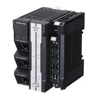
Machine Automation Controller
NJ/NX-series
CPU Unit
Brand: Omron
|
Category: Controller
|
Size: 13 MB
Table of Contents
-
Nx7012
-
-
Nx1023
-
-
Versions
23 -
-
Nj10127
-
-
Features
32 -
Axes
74 -
Axes Groups
92 -
-
Introduction
116 -
Axis Parameters
119 -
Introduction
154 -
Positions
170 -
-
Manual Operation197
-
-
Outline
198 -
Jogging
201 -
Section 8 Homing
206 -
Outline
206 -
Homing Procedure
209 -
Homing Operation
217 -
-
-
Stopping229
-
Override Factors234
-
-
Gear Operation235
-
Cam Operation237
-
Positions237
-
Cam Tables238
-
Combining Axes247
-
-
Other Functions
295-
Torque Limit296
-
Latching296
-
Zone Monitoring297
-
Software Limits298
-
-
-
-
Troubleshooting397
-
-
Appendices
399 -
Terminology
430

Omron NX102-90 Series User Manual (280 pages)
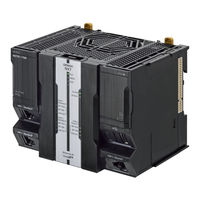
Machine Automation Controller, CPU Unit Built-in EtherCAT Port
Brand: Omron
|
Category: Controller
|
Size: 18 MB
Table of Contents
-
Versions
23 -
-
Introduction33
-
-
-
-
Programming196
-
Online Debugging197
-
-
Troubleshooting199
-
-
Troubleshooting
201 -
-
-
Introduction224
-
-
Appendices
237 -
A-5 Terminology
267 -
-
A-5 Terminology269
-
Advertisement
Omron NX102-90 Series User Manual (68 pages)
Machine Automation Controller, NX-series CPU Unit, FINS Function
Brand: Omron
|
Category: Computer Hardware
|
Size: 0 MB
Table of Contents
Omron NX102-90 Series User Manual (66 pages)
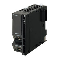
Machine Automation Controller CPU Unit
Brand: Omron
|
Category: Controller
|
Size: 1 MB
Table of Contents

Omron NX102-90 Series Instruction & Reference Manual (20 pages)
Machine Automation Controller
Brand: Omron
|
Category: Controller
|
Size: 0 MB
Advertisement