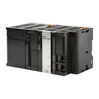
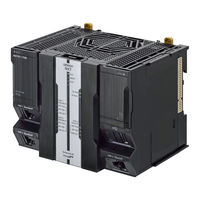
Omron NJ301 series PLC CPU Unit Manuals
Manuals and User Guides for Omron NJ301 series PLC CPU Unit. We have 16 Omron NJ301 series PLC CPU Unit manuals available for free PDF download: User Manual, Owner's Manual, Startup Manual, Network Connection Manual, Connection Manual, Practices Manual

Omron NJ301 series User Manual (578 pages)
Machine Automation Controller, CPU Unit Built-in EtherNet/IP Port
Brand: Omron
|
Category: Controller
|
Size: 13 MB
Table of Contents
Advertisement
Omron NJ301 series Owner's Manual (570 pages)
Machine Automation Controller, CPU Unit Built-in EtherNet/IPTM Port
Brand: Omron
|
Category: Controller
|
Size: 15 MB
Table of Contents
Omron NJ301 series User Manual (424 pages)
Machine Automation Controller
NX-series
Digital I/O Units
Brand: Omron
|
Category: I/O Systems
|
Size: 11 MB
Table of Contents
Advertisement
Omron NJ301 series User Manual (306 pages)
Machine Automation Controller
Brand: Omron
|
Category: Controller
|
Size: 7 MB
Table of Contents
Omron NJ301 series Startup Manual (126 pages)
Machine Automation Controller
Brand: Omron
|
Category: Controller
|
Size: 14 MB
Table of Contents
Omron NJ301 series Network Connection Manual (84 pages)
EtherNet/IP Connection Guide
Brand: Omron
|
Category: Controller
|
Size: 4 MB
Table of Contents

Omron NJ301 series Network Connection Manual (78 pages)
Brand: Omron
|
Category: Rfid Systems
|
Size: 2 MB
Table of Contents
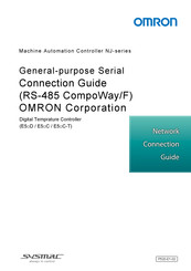
Omron NJ301 series Connection Manual (60 pages)
General-purpose Serial. RS-485 CompoWay/F. Machine Automation Controller,
Brand: Omron
|
Category: Controller
|
Size: 2 MB
Table of Contents

Omron NJ301 series Connection Manual (50 pages)
Machine Automation Controller
Brand: Omron
|
Category: Controller
|
Size: 1 MB
Table of Contents

Omron NJ301 series Network Connection Manual (48 pages)
Machine Automation Controller PATLITE IO-Link Signal Tower LR6-IL Connection
Brand: Omron
|
Category: Controller
|
Size: 2 MB
Table of Contents
Omron NJ301 series Network Connection Manual (46 pages)
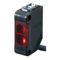
Photoelectric Sensor (IO-Link);
NX-series IO-Link Master Unit;
NX-series EtherCAT Coupler Unit
Brand: Omron
|
Category: Network Hardware
|
Size: 2 MB
Table of Contents

Omron NJ301 series Startup Manual (38 pages)
Machine Automation Controller NJ-series, Simulink PLC Coder & Sysmac Studio
Brand: Omron
|
Category: Controller
|
Size: 2 MB
Table of Contents
Omron NJ301 series Network Connection Manual (44 pages)
Machine Automation Controller, HMS Industrial Networks AB, Anybus X-gateway EtherNet/IP Adapter
Brand: Omron
|
Category: Controller
|
Size: 1 MB
Table of Contents

Omron NJ301 series Connection Manual (38 pages)
Machine Automation Controller
Brand: Omron
|
Category: Controller
|
Size: 2 MB
Table of Contents

Omron NJ301 series Connection Manual (38 pages)
NJ-series;NX-series
Brand: Omron
|
Category: Controller
|
Size: 1 MB
Table of Contents

Omron NJ301 series Practices Manual (30 pages)
Brand: Omron
|
Category: Controller
|
Size: 1 MB
Table of Contents
Advertisement