Omron NJ Series Troubleshooting Manual
Sysmac machine automation controller
Hide thumbs
Also See for NJ Series:
- User manual (668 pages) ,
- Troubleshooting manual (208 pages) ,
- Startup manual (168 pages)
Table of Contents
Advertisement
Quick Links
Download this manual
See also:
User Manual
Advertisement
Table of Contents
Troubleshooting

Related Manuals for Omron NJ Series


Summary of Contents for Omron NJ Series
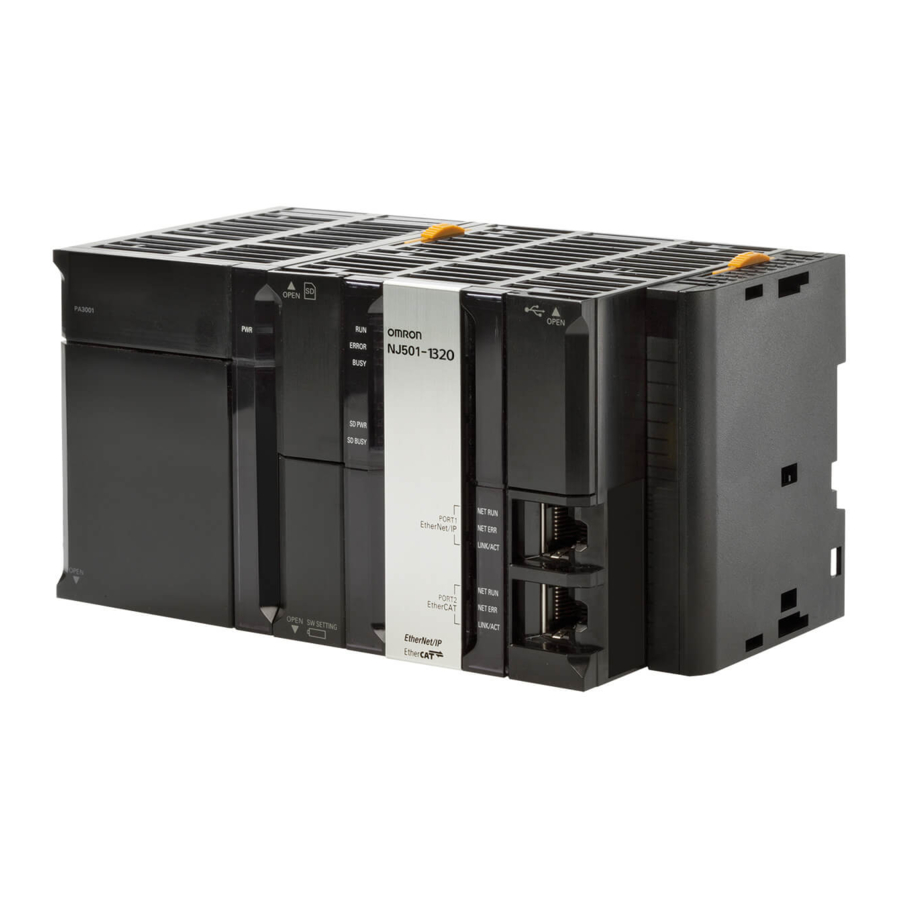
- Page 1 Machine Automation Controller NJ-series Troubleshooting Manual NJ501-15@@ NJ501-14@@ NJ501-13@@ NJ301-12@@ NJ301-11@@ W503-E1-08...
- Page 2 OMRON. No patent liability is assumed with respect to the use of the information contained herein. Moreover, because OMRON is constantly striving to improve its high-quality products, the information contained in this manual is subject to change without notice.
-
Page 3: Introduction
Introduction Introduction Thank you for purchasing an NJ-series CPU Unit. This manual contains information that is necessary to use the NJ-series CPU Unit. Please read this manual and make sure you understand the functionality and performance of the NJ-series CPU Unit before you attempt to use it in a control system. -
Page 4: Relevant Manuals
Other manuals are necessary for specific system configurations and applications. Read all of the manuals that are relevant to your system configuration and application to make the most of the NJ-series CPU Unit. Manual NJ Series NX Series Basic informa- tion Purpose of use ●... - Page 5 Relevant Manuals Manual NJ Series NX Series Basic informa- tion Purpose of use Testing operation and debugging ● ● Using motion control ● Using EtherCAT ● ● Using EtherNet/IP Using the database connection ● service ● ● Using the NX Series ●...
-
Page 6: Manual Structure
Manual Structure Manual Structure Page Structure The following page structure is used in this manual. Level 1 heading 4 Installation and Wiring Level 2 heading Mounting Units Level 3 heading Level 2 heading Gives the current headings. Level 3 heading 4-3-1 Connecting Controller Components The Units that make up an NJ-series Controller can be connected simply by pressing the Units together... - Page 7 Manual Structure Precaution on Terminology In this manual, “download” refers to transferring data from the Sysmac Studio to the physical Controller and “upload” refers to transferring data from the physical Controller to the Sysmac Studio. For the Sysmac Studio, synchronization is used to both upload and download data. Here, “synchronize” means to automatically compare the data for the Sysmac Studio on the computer with the data in the physical Controller and transfer the data in the direction that is specified by the user.
- Page 8 Manual Structure NJ-series Troubleshooting Manual (W503)
-
Page 9: Sections In This Manual
Sections in this Manual Sections in this Manual Overview of Errors Error Troubleshooting Methods Error Tables Index NJ-series Troubleshooting Manual (W503) - Page 10 Sections in this Manual NJ-series Troubleshooting Manual (W503)
-
Page 11: Table Of Contents
CONTENTS CONTENTS Introduction....................... 1 Relevant Manuals...................... 2 Manual Structure ...................... 4 Sections in this Manual.................... 7 Terms and Conditions Agreement ................ 11 Safety Precautions ....................13 Precautions for Safe Use ..................14 Precautions for Correct Use .................. 15 Regulations and Standards ................... 16 Unit Versions...................... - Page 12 CONTENTS Section 3 Error Tables Errors by Source........................3-2 3-1-1 Interpreting Error Descriptions ....................3-2 3-1-2 Errors in the PLC Function Module ..................... 3-2 3-1-3 Errors in the Motion Control Function Module................3-46 3-1-4 Errors in the EtherNet/IP Function Module ................3-74 3-1-5 Errors in the EtherCAT Master Function Module...............
-
Page 13: Terms And Conditions Agreement
Omron’s exclusive warranty is that the Products will be free from defects in materials and workman- ship for a period of twelve months from the date of sale by Omron (or such other period expressed in writing by Omron). Omron disclaims all other warranties, express or implied. - Page 14 Disclaimers Performance Data Data presented in Omron Company websites, catalogs and other materials is provided as a guide for the user in determining suitability and does not constitute a warranty. It may represent the result of Omron’s test conditions, and the user must correlate it to actual application requirements. Actual perfor- mance is subject to the Omron’s Warranty and Limitations of Liability.
-
Page 15: Safety Precautions
Safety Precautions Safety Precautions Refer to the following manuals for safety precautions. • NJ-series CPU Unit Hardware User’s Manual (Cat No. W500) • NJ-series CPU Unit Software User’s Manual (Cat No. W501) NJ-series Troubleshooting Manual (W503) -
Page 16: Precautions For Safe Use
Precautions for Safe Use Precautions for Safe Use Refer to the following manuals for precautions for the safe use of the NJ-series Controller. Installation precautions are also provided for the NJ-series CPU Unit and the NJ-series Controller sys- tem. • NJ-series CPU Unit Hardware User’s Manual (W500) •... -
Page 17: Precautions For Correct Use
Precautions for Correct Use Precautions for Correct Use Refer to the following manuals for precautions for the correct use of the NJ-series Controller. Installation precautions are also provided for the NJ-series CPU Unit and the NJ-series Controller sys- tem. • NJ-series CPU Unit Hardware User’s Manual (W500) •... -
Page 18: Regulations And Standards
Concepts EMC Directive OMRON devices that comply with EC Directives also conform to the related EMC standards so that they can be more easily built into other devices or the overall machine. The actual products have been checked for conformity to EMC standards.* Whether the products conform to the standards in the system used by the customer, however, must be checked by the customer. - Page 19 The NJ-series Controllers comply with the following shipbuilding standards. Applicability to the ship- building standards is based on certain usage conditions. It may not be possible to use the product in some locations. Contact your OMRON representative before attempting to use a Controller on a ship.
-
Page 20: Unit Versions
Unit Versions Unit Versions Unit Versions A “unit version” has been introduced to manage CPU Units in the NJ Series according to differences in functionality accompanying Unit upgrades. Notation of Unit Versions on Products The unit version is given on the ID information label of the products for which unit versions are man- aged, as shown below. - Page 21 Unit Versions Right-click any open space in the Unit Editor and select Production Information. The Production Information Dialog Box is displayed. Simple Display Detailed Display In this example, “Ver.1.00” is displayed next to the unit model. The following items are displayed. CPU Unit CJ-series Units Unit model...
- Page 22 Unit Versions Additional Information Refer to the manual for the specific Unit for the unit versions of the CPU Units, Communications Coupler Units, NX Units, and Safety Control Units to which the database connection service and other functions were added. Unit Versions and Sysmac Studio Versions The events that can occur depend on the unit versions of the NJ-series CPU Unit and the EtherCAT slaves.
-
Page 23: Related Manuals
NJ-series CPU Unit Hardware User’s Manual tions that are provided (Cat. No. W500), NJ-series CPU Unit Software by OMRON. User’s Manual (Cat. No. W501) and NJ-series CPU Unit Motion Control User’s Manual (Cat. No. W507). NJ-series CPU Unit Built-... - Page 24 Related Manuals Manual name Cat. No. Model numbers Application Description NJ-series Troubleshoot- W503 NJ501-@@@@ Learning about the Concepts on managing errors that may be detected ing Manual NJ301-@@@@ errors that may be in an NJ-series Controller and information on indi- detected in an NJ-series vidual errors are described.
- Page 25 Related Manuals Manual name Cat. No. Model numbers Application Description CX-Protocol Operation W344 Creating data transfer Describes operating procedures for the CX-Proto- Manual protocols for general- col. purpose devices con- nected to CJ-series Serial Communications Units. GX-series EtherCAT W488 GX-ID@@@@ Leaning how to connect Provides the specifications of and describes appli- Slave Unit User’s Manual...
-
Page 26: Revision History
Revision History Revision History A manual revision code appears as a suffix to the catalog number on the front and back covers of the manual. W503-E1-08 Cat. No. Revision code Revision code Date Revised content July 2011 Original production March 2012 Added information related to the upgrade to unit version 1.01, made additions and changes to events related to the addition of devices that can be connected, and corrected mistakes. -
Page 27: Overview Of Errors
Overview of Errors This section provides information that is required to troubleshoot errors. It introduces the types of errors that can occur on an NJ-series Controller, the operation that occurs in response to errors, and the methods you can use to check for errors. Refer to Sec- tion 2 Error Troubleshooting Methods for information on troubleshooting errors. -
Page 28: Overview Of Nj-Series Errors
1 Overview of Errors Overview of NJ-series Errors You manage all of the errors that occur on the NJ-series Controller as events. The same methods are used for all events. This allows you to see what errors have occurred and find corrections for them with the same methods for the entire range of errors that is managed (i.e., CPU Unit, NX-series Slave Termi- nals, EtherCAT slaves,* and CJ-series Units). -
Page 29: Cpu Unit Status
1 Overview of Errors Non-fatal Errors These errors are detected and managed with the event management function of the NJ-series Con- troller. You can confirm these errors with the Sysmac Studio or an NS-series PT. Refer to 1-3 Non-fatal Errors for error types and confirmation methods for non-fatal errors. 1-1-2 CPU Unit Status You can check the operating status of the CPU Unit with the PWR, RUN, and ERROR indicators on the... -
Page 30: Fatal Errors
1 Overview of Errors Fatal Errors 1-2-1 Types of Fatal Errors This section describes the errors that cause the operation of the NJ-series CPU Unit to stop. Software connections to the Sysmac Studio or an NS-series PT cannot be made if there is a fatal error in the Controller. -
Page 31: Non-Fatal Errors
1 Overview of Errors Non-fatal Errors Non-fatal errors that occur are managed as events in the NJ-series Controller. You can check the event to find out what type of error occurred. 1-3-1 Types of Non-fatal Errors Overview of Controller Events (Errors and Information) You use the same methods to manage all of the events that occur on the NJ-series Controller. - Page 32 1 Overview of Errors Details on Controller Events (Errors and Information) Sources of Controller Events The Event source information indicates the location where an event occurred. The event source identifies the particular function module in the CPU Unit in which the event occurred. For some func- tion modules, there is more detailed information about the event source.
- Page 33 1 Overview of Errors • Observations These errors do not affect the control operations of the Controller. The observation notifies you of potential problems before they develop into a minor fault level error or worse. • Information Events that are classified as information provide information that do not indicate errors. You can change the event level for some events.
- Page 34 1 Overview of Errors Controller Controller errors Event level information Major fault Partial fault Minor fault Item Observation Information level level level RUN out- put on Power Supply Unit User pro- Stops. Continues. Continues. Continues. Continues. gram execu- tion sta- series Unit Outputs...
- Page 35 1 Overview of Errors Operation in the Function Module Where an Error Event Occurred Event level Major fault level Partial fault level Minor fault level Observation Function module PLC Function User program execution Operation continues. Module stops. All axes stop. (The stop All axes stop.
- Page 36 1 Overview of Errors Unit CPU Unit operation Unit or slave operation CJ-series Basic I/O Unit Refreshing is stopped. • All outputs are turned OFF. • All inputs are turned OFF. CJ-series Special Unit Refreshing is stopped. Depends on the Unit operating specifications (the ERH indicator lights).
- Page 37 1 Overview of Errors First digit of the Classification Meaning code (hex) Hardware errors An error caused by a hardware problem such as an inter- nal part malfunction, contact failure, temperature error, undervoltage, overvoltage, or overcurrent. Data errors An error caused by incorrectly saved data or data cor- ruption in the Controller.
-
Page 38: Checking For Non-Fatal Errors
1 Overview of Errors Variable Name _MC_AX[0..63].Obsr.Code Axis Observation Code _MC_GRP[0..31].MFaultLvl.Code Axes Group Minor Fault Code _MC_GRP[0..31].Obsr.Code Axes Group Observation Code For descriptions of the error codes for the Motion Control Function Module or basic instructions, refer to the descriptions of the corresponding event codes. Refer to the NJ-series CPU Unit Motion Control User’s Manual (Cat. - Page 39 • Lit: Errors for which normal status cannot be recovered through user actions (i.e., errors for which you must replace the CPU Unit or contact your OMRON representative). • Flashing: Errors for which normal status can be recovered through user actions.
-
Page 40: Resetting Non-Fatal Errors
1 Overview of Errors Current Errors Open the Controller Error Tab Page on the NS-series PT’s Troubleshooter to check the current error’s event name, event code, level, source, source details, time, details, and attached information 1 to 4. However, for some NX Units, you cannot check the event names, event codes, details, and attached information for current errors. - Page 41 1 Overview of Errors Always confirm safety at the connected equipment before you reset Controller errors for a CJ- series Special Unit. When the Controller error is reset, the Unit where the Controller error with an event level of observation or higher will be restarted. Before you reset all errors, confirm that no Controller errors with an event level of observation or higher have occurred for the CJ-series Special Unit.
- Page 42 1 Overview of Errors Errors that are Method Operation Description reset Commands from the Resetting Controller Resetting errors for Execute the reset error instruction for the user program errors individual function function module in the user program. modules • For the Motion Control Function Module, you can reset all errors, errors for a par- ticular axis, or errors for a particular axes group.
-
Page 43: Error Troubleshooting Methods
Error Troubleshooting Methods This section describes troubleshooting methods for specific errors. 2-1 Troubleshooting Flowcharts ........2-2 2-1-1 Checking to See If the CPU Unit Is Operating . -
Page 44: Troubleshooting Flowcharts
2 Error Troubleshooting Methods Troubleshooting Flowcharts This section provides basic error identification and troubleshooting flowcharts. Use them when an error occurs in the NJ-series Controller. 2-1-1 Checking to See If the CPU Unit Is Operating When an error occurs in the NJ-series Controller, use the following flowchart to determine whether the error is a fatal error or a non-fatal error. -
Page 45: Troubleshooting Flowchart For Non-Fatal Errors
2 Error Troubleshooting Methods 2-1-2 Troubleshooting Flowchart for Non-fatal Errors For a non-fatal error, use the Sysmac Studio or an NS-series PT to troubleshoot the error with the fol- lowing flowchart. You can use the indicators to check the following: •... -
Page 46: Troubleshooting Fatal Errors
2 Error Troubleshooting Methods Troubleshooting Fatal Errors The section describes the procedure to troubleshoot fatal errors. Power Supply Error Cause Correction Power is not being input. Turn ON the power. The voltage is outside of the allowable Check the Controller’s power supply system, and correct it so that the range for the power supply. -
Page 47: Troubleshooting Non-Fatal Errors
2 Error Troubleshooting Methods Troubleshooting Non-fatal Errors 2-3-1 Identifying and Resetting Errors with the Sysmac Studio Troubleshooting functions are provided by the Sysmac Studio. You can use the troubleshooting func- tions to identify errors that occur in a Controller, and reset the errors. Displaying Errors on the Sysmac Studio If an error occurs while the Sysmac Studio is online with the CPU Unit, the Sysmac Studio notifies the user of the error in the Controller Status Pane. - Page 48 2 Error Troubleshooting Methods Checking Current Errors and the Event Logs with the Sysmac Studio Checking Current Errors with the Sysmac Studio You can click the Controller Errors Tab in the Troubleshooting Window to read information on cur- rent errors in the Controller. The Controller Errors Tab Page lists the current errors in order of their levels.
- Page 49 2 Error Troubleshooting Methods Displaying Event Logs with the Sysmac Studio With Sysmac Studio, you can check a log of the Controller events that previously occurred on the Controller Event Log Tab Page. You can select the event logs and levels to display in the Display Settings Area. Information on the events that you specify are displayed in the detailed information area.
- Page 50 2 Error Troubleshooting Methods To eliminate the cause of the error, first select the item to perform from the Action and Correction list. When you select the appropriate step in the Action and Correction list, either the Jump to Error or Error Help Button is enabled, depending on the contents.
-
Page 51: Identifying And Resetting Errors With An Ns-Series Pt
Identifying and Resetting Errors with an NS-series PT You can connect one of the following OMRON NS-series PTs to an NJ-series CPU Unit through an Eth- erNet/IP network, and use it to read and reset errors that occurred in the Controller. (The Trouble- shooter of the PT is used.) - Page 52 2 Error Troubleshooting Methods Resetting Errors with an NS-series PT You can use the Troubleshooter in an NS-series PT to reset errors that occur in the Controller. Before you attempt to reset a Controller error, isolate and remove the cause of the error. Click the Select Button in the List View to display information such as the error’s causes and correc- tions.
-
Page 53: Identifying And Resetting Errors From The User Program
2 Error Troubleshooting Methods In order to reset the Controller errors, it is necessary to confirm your rights according to the operation authority settings for the Troubleshooter. Refer to the NS-series Programmable Terminals Programming Manual (Cat. No. V073) for details on the operation authority. 2-3-3 Identifying and Resetting Errors from the User Program In an NJ-series Controller, you can check for errors that have occurred from the user program. - Page 54 2 Error Troubleshooting Methods Example of Error Detection for the EtherCAT Master Function Module Name Data type Initial value Comment Trigger BOOL FALSE Get Condition EC_Error BOOL FALSE EtherCAT Master Error Flag EC_Error GetECError Trigger Level Code Resetting Controller Errors with Instructions You can use the instructions that are provided to reset errors in the user program to reset errors that occur in the Controller.
-
Page 55: Checking For Errors With System-Defined Variables
2 Error Troubleshooting Methods 2-3-4 Checking for Errors with System-defined Variables The system-defined variables include an Error Status variable, which shows the error status. The fol- lowing diagram shows the structure of this variable. The system determines the error status of each level by logically ORing the error status information of the next lower level. -
Page 56: Troubleshooting When You Cannot Go Online From The Sysmac Studio
2 Error Troubleshooting Methods Troubleshooting When You Cannot Go Online from the Sysmac Studio The section describes the procedure to troubleshoot when you cannot go online with the CPU Unit from the Sysmac Studio. 2-4-1 Causes and Correction When You Cannot Go Online from the Sysmac Studio The following table lists the possible causes when you cannot go online with the NJ-series CPU Unit from the Sysmac Studio. -
Page 57: Troubleshooting For Each Cause
2 Error Troubleshooting Methods 2-4-2 Troubleshooting for Each Cause This section provides troubleshooting methods for incorrect settings, fault communications paths, and high system service loads. Troubleshooting Incorrect Settings and Faulty Communications Path If the Sysmac Studio cannot go online with the CPU Unit, troubleshoot the problem with the following flowchart. - Page 58 2 Error Troubleshooting Methods Remote Connection to Peripheral USB Port Sysmac Studio cannot connect to CPU Unit. Is power supplied to the Controller? Turn ON the power supply to the Controller. Can the Sysmac Studio go online with CPU Unit? Are the USB cable and Insert the cable connectors all the way Ethernet cables...
- Page 59 2 Error Troubleshooting Methods Direct Connection with EtherNet/IP Port Sysmac Studio cannot Sysmac Studio cannot connect to CPU Unit. connect to CPU Unit. Is power supplied to the Controller? Is power supplied to the Controller? Turn ON the power supply to the Controller. Turn ON the power supply to the Controller.
- Page 60 2 Error Troubleshooting Methods Ethernet Hub Connection Sysmac Studio cannot connect to CPU Unit. Is power supplied to the Controller? Turn ON the power supply to the Controller. Can the Sysmac Studio go online with CPU Unit? Insert the cable connectors at the personal computer,Ethernet switches, and the Controller until they lock into place.
- Page 61 2 Error Troubleshooting Methods Set the IP address for the personal computer. Use the default IP address for the Controller or Is the same IP address set for connect the Sysmac Studio to the Controller more than one node (computer with a USB cable and set the required IP or Controller) in the same address.
- Page 62 2 Error Troubleshooting Methods Safe Mode Operation If the Controller is started when the CPU Unit is in Safe Mode, the CPU Unit will start in PROGRAM mode even if the startup mode is set to RUN mode. This increases the ratio of system service pro- cessing that is performed by the CPU Unit, which makes it easier for the Sysmac Studio to go online with the CPU Unit.
- Page 63 Error Tables This section lists all of the errors (events) that can occur on NJ-series Controllers. 3-1 Errors by Source ..........3-2 3-1-1 Interpreting Error Descriptions .
-
Page 64: Error Tables
3 Error Tables Errors by Source This section provides tables of errors (events) by source. Within each source, errors are given by func- tional classifications. Events that are not errors are also given in the tables. 3-1-1 Interpreting Error Descriptions The contents of the error tables are described below. - Page 65 3 Error Tables Errors for Self Diagnosis Level Event code Event name Meaning Assumed cause Reference Info 00090000 hex DIP Switch An error was • There is an error in the DIP NJ-series Setting Error detected in the DIP switch setting. CPU Unit switch setting.
- Page 66 3 Error Tables Level Event code Event name Meaning Assumed cause Reference Obs Info 00080000 hex Real-Time The real-time clock • The CPU Unit clock has failed. NJ-series Clock Failed in the CPU Unit CPU Unit failed. Hardware User’s Manual (Cat.
- Page 67 3 Error Tables Level Event code Event name Meaning Assumed cause Reference Info 10070000 hex SD Memory The power supply • The Controller power supply NJ-series Card Access to the Controller was turned OFF while the SD CPU Unit Power OFF was interrupted BUSY indicator was lit.
- Page 68 3 Error Tables Level Event code Event name Meaning Assumed cause Reference Obs Info 24050000 hex Duplicate The same unit num- • The same unit number is set for NJ-series Unit Number ber is set for more more than one Special I/O Unit CPU Unit than one Special or more than one CPU Bus...
- Page 69 3 Error Tables Level Event code Event name Meaning Assumed cause Reference Obs Info 80010000 hex Illegal Packet An illegal packet • Noise NJ-series Discarded was received during CPU Unit message communi- Hardware cations. The illegal User’s Manual packet was dis- (Cat.
- Page 70 3 Error Tables Errors Related to Controller Operation Level Event code Event name Meaning Assumed cause Reference Obs Info 10200000 hex User Pro- The user program • The user program or Controller NJ-series gram/Con- or Controller Con- Configurations and Setup are CPU Unit troller figurations and...
- Page 71 3 Error Tables Level Event code Event name Meaning Assumed cause Reference Info 10270000 hex Error in Start- An error was • An SD Memory Card is not NJ-series (Ver. 1.03) ing Auto- detected in pre-exe- inserted. CPU Unit matic cution checks for Hardware •...
- Page 72 3 Error Tables Level Event code Event name Meaning Assumed cause Reference Obs Info 10260000 hex Trace Setting The power supply • The power supply was inter- NJ-series Transfer Fail- was interrupted rupted while transferring the CPU Unit while transferring trace settings.
- Page 73 3 Error Tables Level Event code Event name Meaning Assumed cause Reference Info 102B0000 hex Restore An error was • An SD Memory Card is not NJ-series (Ver. 1.03) Operation detected in pre-exe- inserted. CPU Unit Failed to cution checks for a Hardware •...
- Page 74 3 Error Tables Level Event code Event name Meaning Assumed cause Reference Obs Info 90010000 hex Clock The clock time was • The clock time was changed. NJ-series Changed changed. CPU Unit Hardware User’s Manual (Cat. No. W500) NJ-series CPU Unit Soft- ware User’s Manual (Cat.
- Page 75 3 Error Tables Level Event code Event name Meaning Assumed cause Reference Info 901B0000 hex Backup Com- The backup opera- • The backup operation ended NJ-series (Ver. 1.03) pleted tion ended nor- normally. CPU Unit mally. Hardware User’s Manual (Cat. No. W500) NJ-series CPU Unit Soft-...
- Page 76 3 Error Tables Level Event code Event name Meaning Assumed cause Reference Obs Info 80110000 hex Packet Dis- One or more pack- • An attempt was made to send a NJ-series carded ets were discarded. FINS response with over 2002 CPU Unit Soft- bytes.
- Page 77 3 Error Tables Level Event code Event name Meaning Assumed cause Reference Info 80120000 hex Packet Dis- One or more pack- • A FINS response was received NJ-series carded ets were discarded. with the destination network CPU Unit Soft- address (DNA) set to the local ware User’s network and the destination Manual (Cat.
- Page 78 3 Error Tables Instructions A version in parentheses in the Event code column is the unit version of the CPU Unit when the event code was added. Level Refer- Event code Event name Meaning Assumed cause ence Info 54010400 hex Input Value Out of An input parameter for an •...
- Page 79 3 Error Tables Level Refer- Event code Event name Meaning Assumed cause ence Info 54010406 hex Illegal Data Posi- A memory address or data • A memory address NJ-series tion Specified size that was specified for that was specified for Instruc- the instruction is not suit- an instruction was out-...
- Page 80 3 Error Tables Level Refer- Event code Event name Meaning Assumed cause ence Info 54010413 hex Undefined CJ- The required specification • The required AT speci- NJ-series series Memory is missing for a variable for fication is missing for a Instruc- Address which CJ-series Unit mem-...
- Page 81 3 Error Tables Level Refer- Event code Event name Meaning Assumed cause ence Info 54010C00 hex Illegal Serial Com- The Serial Communica- • The serial communi- NJ-series munications Mode tions Unit is not in the serial cations port for the Instruc- communications mode Serial Communica-...
- Page 82 3 Error Tables Level Refer- Event code Event name Meaning Assumed cause ence Info 54011409 hex That File Name An instruction could not be • A file already exists NJ-series Already Exists executed because the file with the same name Instruc- name specified for the as the name specified...
- Page 83 3 Error Tables Level Refer- Event code Event name Meaning Assumed cause ence Info 54011807 hex Packet Monitoring A Start EtherCAT Packet • The Start EtherCAT NJ-series Function in Opera- Monitor instruction was Packet Monitor Instruc- tion executed when EtherCAT instruction was exe- tions Ref- packet monitoring was...
- Page 84 3 Error Tables Level Refer- Event code Event name Meaning Assumed cause ence Info 54011C04 hex CIP Timeout A CIP timeout occurred • A device does not NJ-series during execution of a CIP exist for the specified Instruc- communications instruc- IP address.
- Page 85 3 Error Tables Level Refer- Event code Event name Meaning Assumed cause ence Info 54012003 hex Status Error The status was not suit- • SktUDPRcv Instruc- NJ-series able for execution of the tion Instruc- instruction. tions Ref- • The socket is receiv- erence ing data.
- Page 86 3 Error Tables Level Refer- Event code Event name Meaning Assumed cause ence Info 54012006 hex Socket Timeout A timeout occurred for a • SktTCPAccept instruc- NJ-series socket service instruction. tion: There was no Instruc- request for a connec- tions Ref- tion from the remote erence node during the user-...
- Page 87 3 Error Tables Level Refer- Event code Event name Meaning Assumed cause ence Info 54012400 hex No Execution Right An instruction to change • An instruction to NJ-series (Ver. 1.02) the settings of an Ether- change the settings of Instruc- Net/IP port was executed the built-in EtherNet/IP tions Ref-...
- Page 88 • A motion control instruction that speci- fies phase Z (_mcEncoderMark) as the trigger conditions was executed for an axis that is mapped to an OMRON GX- EC02@@ EtherCAT Encoder slave. 54015420 hex Electronic Gear The parameter specified for • Instruction input...
- Page 89 3 Error Tables Level Refer- Event code Event name Meaning Assumed cause ence Info 54015422 hex Target Velocity The parameter specified for • Instruction input NJ-series Setting Out of the Velocity input variable parameter exceeded Instruc- Range to a motion control instruc- the valid range of the tions Ref- tion is out of range.
- Page 90 3 Error Tables Level Refer- Event code Event name Meaning Assumed cause ence Info 54015431 hex Travel Mode Selec- The parameter specified for • Instruction input NJ-series tion Out of Range the MoveMode input vari- parameter exceeded Instruc- able to a motion control the valid range of the tions Ref- instruction is out of range.
- Page 91 3 Error Tables Level Refer- Event code Event name Meaning Assumed cause ence Info 5401543A hex Synchronization A synchronized control • The MC_CamOut NJ-series Stopped motion control instruction (End Cam Operation) Instruc- was executed, but condi- instruction was exe- tions Ref- tions required for execution cuted even though the erence...
- Page 92 3 Error Tables Level Refer- Event code Event name Meaning Assumed cause ence Info 54015440 hex Axes Group Can- Execution of the • When the NJ-series not Be Enabled MC_GroupEnable (Enable MC_GroupEnable Instruc- Axes Group) instruction (Enable Axes Group) tions Ref- failed.
- Page 93 3 Error Tables Level Refer- Event code Event name Meaning Assumed cause ence Info 54015445 hex Insufficient Travel There is not sufficient travel • There was not suffi- NJ-series Distance to distance to accelerate or cient travel distance to Instruc- Achieve Blending decelerate to the transit accelerate the current...
- Page 94 3 Error Tables Level Refer- Event code Event name Meaning Assumed cause ence Info 5401544A hex Instruction Execu- An instruction that cannot • An instruction that NJ-series tion Error Caused be used when the Count cannot be used when Instruc- by Count Mode Mode is set to Rotary Mode the Count Mode is set...
- Page 95 3 Error Tables Level Refer- Event code Event name Meaning Assumed cause ence Info 54015456 hex Motion Control An attempt was made to • A parameter for an NJ-series Instruction Re-exe- change the parameter for input variable that can- Instruc- cution Disabled the Periodic input variable not be changed for re-...
- Page 96 3 Error Tables Level Refer- Event code Event name Meaning Assumed cause ence Info 5401545E hex Motion Control An attempt was made to • A parameter for an NJ-series Instruction Re-exe- change the parameter for input variable that can- Instruc- cution Disabled the MoveMode input vari- not be changed for re-...
- Page 97 3 Error Tables Level Refer- Event code Event name Meaning Assumed cause ence Info 54015466 hex Instruction Execu- High-speed homing or an • High-speed homing NJ-series tion Error with interpolation instruction was executed when Instruc- Undefined Home was executed when home home was undefined.
- Page 98 3 Error Tables Level Refer- Event code Event name Meaning Assumed cause ence Info 5401546E hex Duplicate Latch ID The same latch ID was • The same latch ID is NJ-series for Trigger Input specified for more than one used simultaneously Instruc- Condition motion control instruction.
- Page 99 3 Error Tables Level Refer- Event code Event name Meaning Assumed cause ence Info 54015478 hex Target Position The parameter specified for • Instruction input NJ-series Setting Out of the Position input variable parameter exceeded Instruc- Range to a motion control instruc- the valid range of the tions Ref- tion is out of range.
- Page 100 3 Error Tables Level Refer- Event code Event name Meaning Assumed cause ence Info 5401547F hex Auxiliary/Slave The values of the parame- • The parameters for NJ-series Axis Numbers Not ters for the Auxiliary and the Auxiliary and Instruc- in Ascending Slave input variables to a Slave input variables tions Ref-...
- Page 101 3 Error Tables Level Refer- Event code Event name Meaning Assumed cause ence Info 5401548B hex Slave Travel Dis- The parameter specified for • The instruction input NJ-series tance Specifica- the SlaveDistance input parameter exceeded Instruc- tion Out of Range variable to a motion control the range of 40-bit tions Ref-...
- Page 102 3 Error Tables Level Refer- Event code Event name Meaning Assumed cause ence Info 54015496 hex Master Axis Gear The parameter specified for • Instruction input NJ-series Ratio Numerator the RatioNumeratorMaster parameter exceeded Instruc- Out of Range input variable to a motion the valid range of the tions Ref- control instruction is out of...
- Page 103 3 Error Tables Level Refer- Event code Event name Meaning Assumed cause ence Info 54015703 hex Cannot Change The MC_ChangeAxisUse • The NJ-series (Ver. 1.06) Axis Use (Change Axis Use) instruc- MC_ChangeAxisUse Instruc- tion was executed in a way (Change Axis Use) tions Ref- that would cause the maxi- instruction was exe-...
- Page 104 3 Error Tables Level Refer- Event code Event name Meaning Assumed cause ence Info 54015723 hex Switch Structure The value of TrackNumber • The value of the mem- NJ-series (Ver. 1.06) Track Number Set- that is specified in the ber of the structure Instruc- ting Out of Range Switches in-out variable to...
- Page 105 3 Error Tables Level Refer- Event code Event name Meaning Assumed cause ence Info 5401572D hex Number of Array The number of elements in • The number of ele- NJ-series (Ver. 1.06) Elements in Track an array in the structure ments in an array of Instruc- Option Structure...
- Page 106 3 Error Tables Level Refer- Event code Event name Meaning Assumed cause ence Info 54016441 hex Target Position The specified position • The parameter speci- NJ-series Negative Software exceeds the negative soft- fied for the Position Instruc- Limit Exceeded ware limit. input variable to the tions Ref- instruction is beyond...
- Page 107 3 Error Tables Level Refer- Event code Event name Meaning Assumed cause ence Info 54016443 hex Positive Limit Input An instruction was exe- • An instruction for a NJ-series cuted for a motion in the motion in the positive Instruc- positive direction when the direction was exe- tions Ref-...
-
Page 108: Errors In The Motion Control Function Module
3 Error Tables 3-1-3 Errors in the Motion Control Function Module The section provides tables of the errors (events) that can occur in the Motion Control Function Module. They are divided into the following functional classifications. • General motion control •... - Page 109 3 Error Tables Level Event code Event name Meaning Assumed cause Reference Info 54770000 hex Cam Table The phases are not • Data containing cam table NJ-series Data Error in ascending order phases that are not in ascend- CPU Unit during Cam in the cam table.
- Page 110 3 Error Tables Level Event code Event name Meaning Assumed cause Reference Obs Info 64560000 hex Illegal Follow- The difference • The command current position NJ-series ing Error between the com- was restricted so that the axis CPU Unit mand position and velocity of the slave axis would Motion Con- the actual current...
- Page 111 3 Error Tables Level Event code Event name Meaning Assumed cause Reference Info 74250000 hex Homing The limit signal in • The Operation Selection at NJ-series Direction the homing direc- Negative Limit Input or Opera- CPU Unit Limit Input tion was detected tion Selection at Positive Limit Motion Con- Detected...
- Page 112 3 Error Tables Level Event code Event name Meaning Assumed cause Reference Obs Info 742B0000 hex Invalid Home The setting of the • The set value of the home input NJ-series Input Mask home input mask mask distance when the oper- CPU Unit Distance distance is not suit-...
- Page 113 10 seconds for three consecutive periods after a command veloc- ity of 0 was output. • For an OMRON G5-series Servo Drive, the actual current velocity was not reduced to 10% or less of the maximum velocity within 10 seconds for...
- Page 114 3 Error Tables Level Event code Event name Meaning Assumed cause Reference Obs Info 84400000 hex EtherCAT A communications • A communications error NJ-series Slave Com- error occurred for occurred for the EtherCAT slave CPU Unit munications the EtherCAT slave or NX Unit that is allocated to Motion Con- Error...
- Page 115 3 Error Tables Level Event code Event name Meaning Assumed cause Reference Info 743C0000 hex Cannot Exe- You cannot save a • An attempt was made to exe- NJ-series cute Save cam table to a file cute the MC_SaveCamTable CPU Unit Cam Table when non-volatile instruction when another opera-...
- Page 116 • A motion control instruction that specifies phase Z (_mcEncoderMark) as the trig- ger conditions was executed for an axis that is mapped to an OMRON GX-EC02@@ Ether- CAT Encoder slave. 54200000 hex Electronic The parameter • Instruction input parameter...
- Page 117 3 Error Tables Level Event code Event name Meaning Assumed cause Reference Info 54280000 hex Master Coef- The parameter • Instruction input parameter NJ-series ficient Scal- specified for the exceeded the valid range of the Motion Con- ing Out of MasterScaling input input variable.
- Page 118 3 Error Tables Level Event code Event name Meaning Assumed cause Reference Obs Info 54320000 hex Transition The parameter • Instruction input parameter NJ-series Mode Selec- specified for the exceeded the valid range of the Motion Con- tion Out of TransitionMode input variable.
- Page 119 3 Error Tables Level Event code Event name Meaning Assumed cause Reference Info 543A0000 hex Synchroniza- A synchronized • The MC_CamOut (End Cam NJ-series tion Stopped control motion con- Operation) instruction was exe- Motion Con- trol instruction was cuted even though the trol Instruc- executed, but con- MC_CamIn (Start Cam Opera-...
- Page 120 3 Error Tables Level Event code Event name Meaning Assumed cause Reference Obs Info 54400000 hex Axes Group Execution of the • When the MC_GroupEnable NJ-series Cannot Be MC_GroupEnable (Enable Axes Group) instruc- Motion Con- Enabled (Enable Axes tion was executed, there was a trol Instruc- Group) instruction composition axis that was not...
- Page 121 3 Error Tables Level Event code Event name Meaning Assumed cause Reference Info 54470000 hex Positioning For the • For the MC_GearInPos (Posi- NJ-series Gear Opera- MC_GearInPos tioning Gear Operation) instruc- Motion Con- tion Insuffi- (Positioning Gear tion, the value of the Velocity trol Instruc- cient Target Operation) instruc-...
- Page 122 3 Error Tables Level Event code Event name Meaning Assumed cause Reference Obs Info 544F 0000 hex Setting Out of The parameter • Instruction input parameter NJ-series Range for specified for the exceeded the valid range of the Motion Con- Writing MC SettingValue input input variable.
- Page 123 3 Error Tables Level Event code Event name Meaning Assumed cause Reference Info 54570000 hex Motion Con- An attempt was • A parameter for an input vari- NJ-series trol Instruc- made to change the able that cannot be changed for Motion Con- tion Re- parameter for the...
- Page 124 3 Error Tables Level Event code Event name Meaning Assumed cause Reference Obs Info 545C 0000 hex Motion Con- An attempt was • A parameter for an input vari- NJ-series trol Instruc- made to change the able that cannot be changed for Motion Con- tion Re- parameter for the...
- Page 125 3 Error Tables Level Event code Event name Meaning Assumed cause Reference Info 54630000 hex Motion Con- An attempt was • A parameter for an input vari- NJ-series trol Instruc- made to change the able that cannot be changed for Motion Con- tion Re- SlaveOffset input...
- Page 126 3 Error Tables Level Event code Event name Meaning Assumed cause Reference Obs Info 546B0000 hex Illegal The parameter • The value of the LastPosition NJ-series First/Last specified for the input parameter is less than the Motion Con- Position Size LastPosition input value of the FirstPosition input trol Instruc-...
- Page 127 3 Error Tables Level Event code Event name Meaning Assumed cause Reference Info 54720000 hex Motion Con- An attempt was • A parameter for an input vari- NJ-series trol Instruc- made to change the able that cannot be changed for Motion Con- tion Re- StartMode input...
- Page 128 3 Error Tables Level Event code Event name Meaning Assumed cause Reference Obs Info 547C 0000 hex Circular Inter- It was not possible • For the MC_MoveCircular2D NJ-series polation to create a circular (Circular 2D Interpolation) Motion Con- Radius Set- path for the speci- instruction, it was not possible trol Instruc-...
- Page 129 3 Error Tables Level Event code Event name Meaning Assumed cause Reference Info 54830000 hex Master Dis- The parameter • Instruction input parameter NJ-series tance in specified for the exceeded the valid range of the Motion Con- Acceleration MasterDistance- input variable. trol Instruc- Specification ACC input variable...
- Page 130 3 Error Tables Level Event code Event name Meaning Assumed cause Reference Obs Info 548E 0000 hex Auxiliary and The same axis was • The parameter is the same for NJ-series Slave specified for the the Auxiliary and Slave input Motion Con- Defined as Auxiliary and Slave...
- Page 131 3 Error Tables Level Event code Event name Meaning Assumed cause Reference Info 54970000 hex Master Axis The parameter • Instruction input parameter NJ-series Gear Ratio specified for the exceeded the valid range of the Motion Con- Denominator RatioDenominator- input variable. trol Instruc- Out of Range Master input vari-...
- Page 132 3 Error Tables Level Event code Event name Meaning Assumed cause Reference Obs Info 57020000 hex Axis Use • The MC_ChangeAxisUse NJ-series (Ver. 1.04) Change Error MC_ChangeAxisUs (Change Axis Use) instruction Motion Con- e (Change Axis was executed when the axis trol Instruc- Use) instruction was not stopped or when the...
- Page 133 3 Error Tables Level Event code Event name Meaning Assumed cause Reference Info 57300000 hex Motion Con- A ReferenceType • A ReferenceType in-out vari- NJ-series (Ver. 1.06) trol Instruc- in-out variable that able that cannot be changed Motion Con- tion Multi- cannot be changed during multi-execution of trol Instruc-...
- Page 134 3 Error Tables Level Event code Event name Meaning Assumed cause Reference Obs Info 64440000 hex Negative An instruction for a • An instruction for a motion in NJ-series Limit Input motion in the nega- the negative direction was exe- Motion Con- tive direction was cuted when the negative limit...
- Page 135 3 Error Tables Level Event code Event name Meaning Assumed cause Reference Info 57290000 hex Track Option The value of • The value of the member of the NJ-series (Ver. 1.06) Structure ON OnCompensation structure variable that was Motion Con- Compensa- that is specified in specified for the in-out variable...
-
Page 136: Errors In The Ethernet/Ip Function Module
3 Error Tables 3-1-4 Errors in the EtherNet/IP Function Module Built-in EtherNet/IP Port on CPU Unit Level Event code Event name Meaning Assumed cause Reference Obs Info 04200000 hex Communica- A hardware error • Communications Controller NJ-series tions Control- was detected in the hardware error CPU Unit ler Failure... - Page 137 3 Error Tables Level Event code Event name Meaning Assumed cause Reference Info 34240000 hex FTP Server An error was • Setting error NJ-series Setting Error detected in the FTP CPU Unit • Power was interrupted when a server settings. Built-in Ether- download was in progress for Net/IP Port...
- Page 138 3 Error Tables Level Event code Event name Meaning Assumed cause Reference Obs Info 84080000 hex Tag Data Link A timeout occurred • The power supply to the target NJ-series Timeout in a tag data link. node is OFF. CPU Unit Built-in Ether- •...
- Page 139 3 Error Tables Level Event code Event name Meaning Assumed cause Reference Info 94030000 hex Tag Data Link Tag data links were • Tag data links were stopped by NJ-series Stopped stopped by Network Network Configurator or manip- CPU Unit Configurator or ulation of a system-defined Built-in Ether-...
-
Page 140: Errors In The Ethercat Master Function Module
3 Error Tables 3-1-5 Errors in the EtherCAT Master Function Module Built-in EtherCAT Master in CPU Unit Level Event code Event name Meaning Assumed cause Reference Obs Info 04400000 hex Communica- An error was • The CPU Unit has failed. NJ-series tions Control- detected in the... - Page 141 3 Error Tables Level Event code Event name Meaning Assumed cause Reference Info 84220000 hex Network A slave that is in the • A slave that is in the network NJ-series Configura- network configura- configuration information is not CPU Unit tion Verifica- tion information is connected.
- Page 142 • Initialization of the EtherCAT slave failed. • It was not possible to read the backup parameters from the EtherCAT slave. • Communications with an OMRON Communications Cou- pler Unit or NX Unit failed. 3-80 NJ-series Troubleshooting Manual (W503)
- Page 143 • The EtherCAT network configu- ration in the backup data does not agree with the physical net- work configuration. • An error occurred at an OMRON Communications Cou- pler Unit. The following causes are possi- ble. • Reading a backup file failed...
-
Page 144: Errors In The Db Connection Service Function
3 Error Tables Level Event code Event name Meaning Assumed cause Reference Obs Info 94410000 hex Slave Con- A slave was recon- • An operation to reconnect the NJ-series nected nected for a recon- slave was executed from the CPU Unit nection command. - Page 145 3 Error Tables Level Event code Event name Meaning Assumed cause Reference Info 14D30000 hex SQL Execu- Failed to save the • An SD Memory Card is not NJ-series (Ver. 1.05) tion Failure SQL Execution Fail- inserted. Database Log Save ure Log to the SD Connection •...
- Page 146 3 Error Tables Errors Related to DB Connection Instructions Errors are given as event codes that use the error code as the lower four digits. For descriptions of an error code, refer to the description of the corresponding event code. For example, if the error code for the instruction is 16#3000, refer to the description for event code 5401 3000 hex.
- Page 147 3 Error Tables Level Event code Event name Meaning Assumed cause Reference Info 54013007 hex Too Many DB The number of DB • The relevant instruction was NJ-series (Ver. 1.05) Connections Connections that executed when the maximum Database can be established number of DB Connections that Connection at the same time is...
- Page 148 3 Error Tables Level Event code Event name Meaning Assumed cause Reference Obs Info 5401300B hex SQL Execu- The executed SQL • There is no column with the NJ-series (Ver. 1.05) tion Error statement resulted same name as a structure Database in an error.
-
Page 149: Errors In Slave Terminals
Debug Log is stopped. 3-1-7 Errors in Slave Terminals The section provides tables of the errors (events) that can occur in the following Units in OMRON Slave Terminals. • NX-series EtherCAT Coupler Units • NX-series Digital I/O Units •... - Page 150 3 Error Tables NX-series EtherCAT Coupler Units The section provides a table of the errors (events) that can occur in the following Unit. NX-ECC201 Level Event code Event name Meaning Assumed cause Reference Obs Info 00210000 hex Bus Control- An internal bus •...
- Page 151 3 Error Tables Level Event code Event name Meaning Assumed cause Reference Info 35010000 hex Unit Configu- There is an incon- • An NX Unit that is registered in NX-series ration Verifi- sistency between the Unit configuration informa- EtherCAT cation Error the Unit configura- tion is not connected.
- Page 152 3 Error Tables Level Event code Event name Meaning Assumed cause Reference Obs Info 35090000 hex TxPDO Map- An incorrect TxPDO • An incorrect TxPDO was set, NX-series ping Error was set. (AL-Sta- e.g., the index, subindex, or EtherCAT tus Code: 0024 size was outside of the allow- Coupler Unit hex)
- Page 153 3 Error Tables Level Event code Event name Meaning Assumed cause Reference Info 85030000 hex Communica- The number of • Power to the host controller was NX-series tions Syn- consecutive errors interrupted during process data EtherCAT chronization in receiving the communications.
- Page 154 3 Error Tables Level Event code Event name Meaning Assumed cause Reference Obs Info 10410000 hex Control An error occurred in • There is an error in the area of NX-series Dig- Parameter the control parame- the non-volatile memory in the ital I/O Units Error in Mas- ters that are saved...
- Page 155 3 Error Tables NX-series Analog I/O Units The section provides a table of the errors (events) that can occur in the following Units. NX-AD@@@@ NX-DA@@@@ NX-TS@@@@ Analog Input Units and Analog Output Units Level Event code Event name Meaning Assumed cause Reference Info...
- Page 156 3 Error Tables Level Event code Event name Meaning Assumed cause Reference Obs Info 65090000 hex Unit I/O Dis- A disconnected • Input wiring is broken. NX-series connection input was detected Analog I/O • Input wiring is disconnected. Detected for for channel 7.
- Page 157 3 Error Tables Level Event code Event name Meaning Assumed cause Reference Info 64F1 0000 hex Unit Over The analog input • The analog input data NX-series Range for data for input chan- exceeded the upper limit of the Analog I/O Channel 2 nel 2 exceeded the input range.
- Page 158 3 Error Tables Level Event code Event name Meaning Assumed cause Reference Obs Info 64F7 0000 hex Unit Over The analog input • The analog input data NX-series Range for data for input chan- exceeded the upper limit of the Analog I/O Channel 8 nel 8 exceeded the...
- Page 159 3 Error Tables Level Event code Event name Meaning Assumed cause Reference Info 64FD 0000 hex Unit Under The analog input • The analog input data went NX-series Range for data for input chan- below the lower limit of the input Analog I/O Channel 6 nel 6 went below...
- Page 160 3 Error Tables Level Event code Event name Meaning Assumed cause Reference Obs Info 65100000 hex Sensor Dis- A disconnected • The temperature sensor is NX-series connected temperature sen- damaged or the wires are bro- Analog I/O Error sor was detected. ken.
- Page 161 3 Error Tables Level Event code Event name Meaning Assumed cause Reference Info 90400000 hex Event Log The event log was • The event log was cleared by NX-series Cleared cleared. the user. Analog I/O Units User’s Manual (W522) NX-series System Units The section provides a table of the errors (events) that can occur in the following Units.
- Page 162 3 Error Tables Level Event code Event name Meaning Assumed cause Reference Obs Info 35110000 hex SSI Data Set- There is an error in • The sum of the values set for NX-series ting Error the SSI data set- the Valid Data Length and the Position Inter- tings.
- Page 163 3 Error Tables Level Event code Event name Meaning Assumed cause Reference Info 80200000 hex NX Unit I/O A communications • The NX Unit is not mounted NX-series Communica- error occurred properly. Position Inter- tions Error between the Com- face Units •...
- Page 164 3 Error Tables NX-series Safety Control Units The following table lists the events that can occur for NX-series Safety Control Units with the following model numbers. NX-SL@@@@ NX-SI@@@@ NX-SO@@@@ Safety CPU Units Level Event code Event name Meaning Assumed cause Reference Obs Info 05200000 hex...
- Page 165 3 Error Tables Level Event code Event name Meaning Assumed cause Reference Info 74A10000 hex SF_EDM An error was Refer to information on the diag- NX-series Error detected in execu- nostic code that is given for Safety Control tion of a safety attached information 1 in the NX- Unit User’s function block.
- Page 166 3 Error Tables Level Event code Event name Meaning Assumed cause Reference Obs Info 74AB 0000 hex SF_MutingSe An error was Refer to information on the diag- NX-series q Error detected in execu- nostic code that is given for Safety Control tion of a safety attached information 1 in the NX- Unit User’s...
- Page 167 3 Error Tables Level Event code Event name Meaning Assumed cause Reference Info 80220000 hex NX Message An error was The message communications NX-series Communica- detected in mes- load is high. Safety Control tions Error sage communica- Unit User’s tions for an NX Unit Manual (Z930) and the message frame was dis-...
- Page 168 3 Error Tables Level Event code Event name Meaning Assumed cause Reference Obs Info 35230000 hex Safety Pro- Safety process data • The setting of the FSoE slave NX-series cess Data communications address in the safety process Safety Control Communica- was not estab- data communications settings Unit User’s...
- Page 169 3 Error Tables Level Event code Event name Meaning Assumed cause Reference Info 65280000 hex Stuck-at-high It was detected that • The positive power supply line NX-series Detected at the safety output is in contact with the output sig- Safety Control Safety Output terminal is stuck nal line.
-
Page 170: Errors In Ethercat Slaves
3 Error Tables 3-1-8 Errors in EtherCAT Slaves This section provides tables of the events for which OMRON EtherCAT slaves provide notification to the NJ-series CPU Unit. • Block I/O (GX-series EtherCAT Slave Units) • Servo G5 (G5-series AC Servo Drives with Built-in EtherCAT Communications) and G5 Linear (G5- series Linear Motors/Drives with Built-in EtherCAT Communications Linear Motor Type) •... - Page 171 3 Error Tables Level Event code Event name Meaning Assumed cause Reference Info 04A80000 hex Control The voltage • Power supply undervoltage. Or, Cylinder-type Power Sup- between the posi- the power supply voltage Motor Manual ply Under- tive and negative dropped because there was (Cat.
- Page 172 3 Error Tables Level Event code Event name Meaning Assumed cause Reference Obs Info 04AC0000 hex Overcurrent The current flowing • A short-circuit, line-to-ground Cylinder-type through the con- fault, contact failure, or insula- Motor Manual verter exceeded the tion failure occurred on the U, V, (Cat.
- Page 173 3 Error Tables Level Event code Event name Meaning Assumed cause Reference Info 08090000 hex Encoder There is a commu- • The power supply voltage of the Cylinder-type Communica- nications error for encoder is low. Motor Manual tions Error the encoder. (Cat.
- Page 174 3 Error Tables Level Event code Event name Meaning Assumed cause Reference Obs Info 08160000 hex Phase-Z An error such as • An error such as broken wiring Cylinder-type Connection broken wiring was was detected in the external Motor Manual Error detected in the encoder phase-Z connection.
- Page 175 3 Error Tables Level Event code Event name Meaning Assumed cause Reference Info 18230000 hex Absolute The encoder • Servomotor failed. Cylinder-type Encoder detected a multi- Motor Manual Multi-rotation rotation counter (Cat. No. I576) Counter Error error. 24680000 hex Motor Non- The Servo Drive •...
- Page 176 3 Error Tables Level Event code Event name Meaning Assumed cause Reference Obs Info 34E20000 hex Overload When the feedback • Operation was continued for a Cylinder-type value for long time while overloaded. Motor Manual torque/force com- (Cat. No. I576) •...
- Page 177 3 Error Tables Level Event code Event name Meaning Assumed cause Reference Info 38400000 hex Overspeed 2 The Servomotor • The velocity command value is Cylinder-type rotation too large. Motor Manual speed/motor speed (Cat. No. I576) • There is overshooting. exceeded the value and Linear •...
- Page 178 3 Error Tables Level Event code Event name Meaning Assumed cause Reference Obs Info 38490000 hex Interface Out- There is an unde- • There is an undefined number Cylinder-type put Function fined number speci- specification in the output sig- Motor Manual Number Error fication in the nal (OUTM1) function alloca-...
- Page 179 3 Error Tables Level Event code Event name Meaning Assumed cause Reference Info 38520000 hex Function Set- The function that • The electronic gear object ratio Cylinder-type ting Error was set does not was not 1:1 when the communi- Motor Manual support the com- cations period was set to 500 (Cat.
- Page 180 3 Error Tables Level Event code Event name Meaning Assumed cause Reference Obs Info 38560000 hex Motor Auto- The current • The Current Loop Proportional Linear Motor setting Error exceeded the limit Gain or the Current Loop Inte- Manual (Cat. when it was applied gral Gain was too large before No.
- Page 181 3 Error Tables Level Event code Event name Meaning Assumed cause Reference Info 74810000 hex Command A mistake was • When bit 09 (Remote) of the Cylinder-type Error made in using a Statusword (6041 hex) was set Motor Manual command. to 1 (remote), and the Servo (Cat.
- Page 182 3 Error Tables Level Event code Event name Meaning Assumed cause Reference Obs Info 84B20000 hex EtherCAT An undefined com- • An undefined communications Cylinder-type Illegal State munications state state change command was Motor Manual Change Error change command received. (Cat.
- Page 183 3 Error Tables Level Event code Event name Meaning Assumed cause Reference Info 08030000 hex Encoder Encoder communi- • There is insufficient power sup- Cylinder-type Communica- cations errors ply voltage for the encoder. Motor Manual tions Warn- occurred in series (Cat.
- Page 184 3 Error Tables Level Event code Event name Meaning Assumed cause Reference Obs Info 74800000 hex Command A command could • The absolute multi-rotation Cylinder-type Warning not be executed. counter was cleared when the Motor Manual Servo was not OFF when using (Cat.
- Page 185 3 Error Tables Level Event code Event name Meaning Assumed cause Reference Info 04BA0000 hex Connection An error occurred in • Contact failure between the MX2/RX Error the connection Inverter and the EtherCAT Series Inverter between between the Communications Unit for the EtherCAT Inverter and Inverter and the...
- Page 186 3 Error Tables Level Event code Event name Meaning Assumed cause Reference Obs Info 48020000 hex System Error An error occurred in • A serious error occurred in the FH/FZ5 Vision the system. system in the Controller. System FH/FZ5 Series User’s Manual for Communi- cations Set-...
- Page 187 3 Error Tables EtherCAT FQ-M-series Specialized Vision Sensors for Positioning Level Event code Event name Meaning Assumed cause Reference Info 78080000 hex TRIG Input A TRIG signal was • A TRIG signal was input when FQ-M-series Error input when the the BUSY signal for Sensor Specialized BUSY signal for...
- Page 188 3 Error Tables Level Event code Event name Meaning Assumed cause Reference Obs Info 24780000 hex Number of The number of Sen- • The set value does not match EtherCAT Digi- Sensors Ver- sors that is con- the number of Sensors that are tal-type Sen- ify Error nected does not...
- Page 189 3 Error Tables Level Event code Event name Meaning Assumed cause Reference Info 247D 0000 hex Number of Too many Sensors • More than the maximum num- EtherCAT Digi- Sensors Over are connected at ber of Sensors are connected tal Sensor at Distrib- Distributed Sensor at Distributed Sensor Unit.
- Page 190 3 Error Tables Level Event code Event name Meaning Assumed cause Reference Obs Info 74930000 hex TIMING input TIMING input pro- • TIMINGx input turned ON in the ZW-CE1@T error cessing was not FUN mode. Confocal Fiber executed correctly. Type Displace- •...
-
Page 191: Errors In Cj-Series Units
3 Error Tables 3-1-9 Errors in CJ-series Units The section provides tables of the events that can occur in the CJ-series Units. • Analog I/O Units • Process I/O Units • Temperature Control Units • ID Sensor Units • High-speed Counter Units •... - Page 192 3 Error Tables Level Event code Event name Meaning Assumed cause Reference Obs Info 34850000 hex Mean Value There is a mistake • There is a mistake in the setting CJ-series Processing in the setting of the of the number of samplings for Analog I/O Setting Error number of sam-...
- Page 193 3 Error Tables Level Event code Event name Meaning Assumed cause Reference Info 348C0000 hex I/O Number The I/O numbers • The I/O numbers that were CJ-series Specification specified in Adjust- specified in Adjustment Mode Analog I/O Error in ment Mode are not are not enabled.
- Page 194 3 Error Tables CJ-series Temperature Control Units The section provides tables of the events that can occur in the following Units. CJ1W-TC003 CJ1W-TC004 CJ1W-TC103 CJ1W-TC104 Level Event code Event name Meaning Assumed cause Reference Obs Info 04680000 hex Cold Junction An error occurred in •...
- Page 195 3 Error Tables Level Event code Event name Meaning Assumed cause Reference Info 24400000 hex Unit Status, An error occurred in • The setting of the Connected CJ-series ID Antenna the Antenna. Antenna Setting (device vari- Sensor Units Error able *_Ch#_AntConn) does not Operation agree with the Antenna that is Manual for NJ-...
- Page 196 3 Error Tables Level Event code Event name Meaning Assumed cause Reference Obs Info 64910000 hex Results Infor- ID system error 2 • System error 2 occurred. CJ-series ID mation, ID occurred. Sensor Units System Error Operation Manual for NJ- series CPU Unit (Cat.
- Page 197 3 Error Tables CJ-series Serial Communications Units The section provides tables of the events that can occur in the following Units. CJ1W-SCU22 CJ1W-SCU32 CJ1W-SCU42 Level Event code Event name Meaning Assumed cause Reference Info 04740000 hex Error Log An error occurred in •...
- Page 198 3 Error Tables Level Event code Event name Meaning Assumed cause Reference Obs Info 54AA0000 hex Protocol An error occurred in • Sequence No. Error: An unreg- CJ-series Macro Error the protocol macro. istered number was specified Serial Com- for SeqNo (communications munications sequence number) of the Units Opera-...
- Page 199 3 Error Tables Level Event code Event name Meaning Assumed cause Reference Info 64A30000 hex FCS Check One of the following • Noise CJ-series Error errors occurred in Serial Com- • There was a mistake in the the converted pro- munications CRC code that was attached to tocol at the serial...
- Page 200 3 Error Tables Level Event code Event name Meaning Assumed cause Reference Obs Info 64A50000 hex Comparison A comparison error • Loopback test jig failure. CJ-series Error occurred. Serial Com- • Noise munications • The communications circuits in Units Opera- the Serial Communications Unit tion Manual for are faulty.
- Page 201 3 Error Tables Level Event code Event name Meaning Assumed cause Reference Info 846A0000 hex Framing A frame error • In Serial Gateway Mode or Pro- CJ-series Error occurred. tocol Macro Mode: Serial Com- munications • The reception circuits in the Units Opera- Serial Communications Unit tion Manual for...
- Page 202 3 Error Tables CJ-series DeviceNet Units The section provides tables of the events that can occur in the following Units. CJ1W-DRM21 Level Event code Event name Meaning Assumed cause Reference Obs Info 04880000 hex Unit Memory An error occurred • There is a source of noise CJ-series Error when writing to...
- Page 203 3 Error Tables Level Event code Event name Meaning Assumed cause Reference Info 34BD0000 hex Verification The slave informa- • A slave that is in the scan list CJ-series Error tion registered in does not exist. DeviceNet the scan list does Units Opera- •...
- Page 204 3 Error Tables Level Event code Event name Meaning Assumed cause Reference Obs Info 34C2 0000 hex Slave I/O The I/O memory in • I/O words are allocated in an CJ-series Refresh Error the destination EM bank that does not exist. DeviceNet CPU Unit for I/O Units Opera-...
- Page 205 3 Error Tables Level Event code Event name Meaning Assumed cause Reference Info 74620000 hex Scan List An operating error • CPU Unit is not in PROGRAM CJ-series Regis- occurred when reg- mode. DeviceNet ter/Clear istering or clearing Units Opera- •...
- Page 206 3 Error Tables Level Event code Event name Meaning Assumed cause Reference Obs Info 84740000 hex Bus Off A Bus Off error • The master and slave have dif- CJ-series Detected occurred (i.e., com- ferent baud rates. DeviceNet munications Units Opera- •...
- Page 207 3 Error Tables CJ-series EtherNet/IP Unit The following table lists the events that can occur for an EtherNet/IP Unit with the following model num- ber. CJ1W-EIP21 Level Event code Event name Meaning Assumed cause Reference Info 047A0000 hex Unit Memory An error occurred •...
- Page 208 3 Error Tables Level Event code Event name Meaning Assumed cause Reference Obs Info 34AB0000 hex Basic Ether- There is an illegal • The power was interrupted dur- CJ-series Eth- net Setting TCP/IP setting. ing a download. erNet/IP Units Error Operation •...
- Page 209 3 Error Tables Level Event code Event name Meaning Assumed cause Reference Info 84E10000 hex BOOTP Connection with the • Server setting error (The CJ-series Eth- Server Error BOOTP server acquired IP address is illegal.) erNet/IP Units failed. Operation • Server is down. Manual for NJ- •...
- Page 210 3 Error Tables Level Event code Event name Meaning Assumed cause Reference Obs Info 84600000 hex Communica- A Slave Unit was • Cable lengths (trunk line and CJ-series tions Error disconnected from branch lines) are unsuitable. CompoNet the network. Master Units •...
-
Page 211: Events In Order Of Event Codes
3 Error Tables Events in Order of Event Codes This section provides a table of all events in order of the event codes. Events that are not errors are also given in the tables. 3-2-1 Interpreting Error Descriptions The contents of the error table is described below. Item Description Event code... -
Page 212: Error Table
3 Error Tables Cat. No. Manual name E413 EtherCAT Digital-type Sensor Communications Unit Operation Manual E429 EtherCAT Digital Sensor Communications Unit Operation Manual Z317 CJ-series ID Sensor Units Operation Manual for NJ-series CPU Unit Z314 FQ-M-series Specialized Vision Sensor for Positioning User’s Manual Z342 FH/FZ5 Vision System FH/FZ5 Series User’s Manual for Communications Settings Z332... - Page 213 3 Error Tables Event code Event name Functional classification Reference 04760000 hex CTS Check Error CJ-series Serial Communications W494 Units 047A0000 hex Unit Memory Error (Device Error) CJ-series EtherNet/IP Units W495 047B0000 hex Non-volatile Memory Error CJ-series EtherNet/IP Units W495 047C0000 hex Communications Controller Error CJ-series EtherNet/IP Units...
- Page 214 3 Error Tables Event code Event name Functional classification Reference 0511 0000 hex* Cold Junction Sensor Error NX-series Analog I/O Units W522 0520 0000 hex* System Error NX-series Safety Control Unit Z930 0521 0000 hex* Internal Circuit Error at Safety Input NX-series Safety Control Unit Z930 0522 0000 hex*...
- Page 215 3 Error Tables Event code Event name Functional classification Reference 100C0000 hex* Event Level Setting Error Errors for Self Diagnosis W500 10200000 hex User Program/Controller Configura- Errors Related to Controller Opera- W500, W501 tions and Setup Transfer Error tion 10210000 hex Illegal User Program Execution ID Errors Related to Controller Opera- W500, W501...
- Page 216 3 Error Tables Event code Event name Functional classification Reference 1440 0000 hex MAC Address Error Built-in EtherCAT Master in CPU Unit W505 1460 0000 hex Absolute Encoder Home Offset Read General Motion Control W507 Error 1461 0000 hex Motion Control Parameter Setting General Motion Control W507 Error...
- Page 217 3 Error Tables Event code Event name Functional classification Reference 24010000 hex Unsupported Unit Detected Errors Related to Unit Configuration W500 24020000 hex Too Many I/O Points Errors Related to Unit Configuration W500 24030000 hex End Cover Missing Errors Related to Unit Configuration W500 24040000 hex Incorrect Unit/Expansion Rack Con-...
- Page 218 3 Error Tables Event code Event name Functional classification Reference 3421 0000 hex Basic Ethernet Setting Error Built-in EtherNet/IP Port on CPU Unit W506 3422 0000 hex TCP/IP Basic Setting Error (Local Built-in EtherNet/IP Port on CPU Unit W506 Port IP Address) 3423 0000 hex TCP/IP Advanced Setting Error (IP Built-in EtherNet/IP Port on CPU Unit W506...
- Page 219 3 Error Tables Event code Event name Functional classification Reference 34AB0000 hex Basic Ethernet Setting Error CJ-series EtherNet/IP Units W495 34AC0000 hex IP Address Table Error CJ-series EtherNet/IP Units W495 34AD0000 hex IP Router Table Error CJ-series EtherNet/IP Units W495 34AE0000 hex Routing Table Error CJ-series EtherNet/IP Units...
- Page 220 3 Error Tables Event code Event name Functional classification Reference 350A0000 hex* RxPDO Mapping Error NX-series EtherCAT Coupler Unit W519 350B0000 hex* Illegal State Transition Request NX-series EtherCAT Coupler Unit W519 Received 350C0000 hex* Error State Transition Received NX-series EtherCAT Coupler Unit W519 350D0000 hex* Synchronization Cycle Setting Error...
- Page 221 3 Error Tables Event code Event name Functional classification Reference 384A0000 hex Interface Output Function Number Servo G5 and G5 Linear I576, I577 Error 2 384B0000 hex External Latch Input Allocation Error Servo G5 and G5 Linear I576, I577 384C0000 hex Overrun Limit Error Servo G5 and G5 Linear I576, I577...
- Page 222 3 Error Tables Event code Event name Functional classification Reference 5401 0413 hex Undefined CJ-series Memory Instructions W502 Address 5401 0414 hex Stack Underflow Instructions W502 5401 0416 hex Illegal Number of Array Elements or Instructions W502 Dimensions 5401 0417 hex Specified Task Does Not Exist Instructions W502...
- Page 223 3 Error Tables Event code Event name Functional classification Reference 54011C02 hex CIP Handle Out of Range Instructions W502 54011C03 hex CIP Communications Resource Over- Instructions W502 flow 54011C04 hex CIP Timeout Instructions W502 54011C05 hex* Class-3 Connection Not Established Instructions W502 54011C06 hex*...
- Page 224 3 Error Tables Event code Event name Functional classification Reference 5401 3012 hex* DB Connection Instruction Execution DB Connection Instructions W527 Timeout 5401 3013 hex* DB Connection Service Error Stop DB Connection Instructions W527 5401 3014 hex* Data Already Spooled DB Connection Instructions W527 5401 3015 hex*...
- Page 225 3 Error Tables Event code Event name Functional classification Reference 5401543C hex Motion Control Instruction Multi-exe- Instructions W502 cution Disabled 5401543D hex Instruction Not Allowed for Encoder Instructions W502 Axis Type 5401543E hex Instruction Cannot Be Executed dur- Instructions W502 ing Multi-axes Coordinated Control 5401543F hex Multi-axes Coordinated Control...
- Page 226 3 Error Tables Event code Event name Functional classification Reference 5401 545A hex Motion Control Instruction Re-execu- Instructions W502 tion Disabled (MasterOffset) 5401 545B hex Motion Control Instruction Re-execu- Instructions W502 tion Disabled (MasterScaling) 5401 545C hex Motion Control Instruction Re-execu- Instructions W502 tion Disabled (MasterStartDistance)
- Page 227 3 Error Tables Event code Event name Functional classification Reference 5401547B hex Cam Master Axis Following First Posi- Instructions W502 tion Setting Out of Range 5401547C hex Circular Interpolation Radius Setting Instructions W502 Error 5401547D hex Circular Interpolation Radius Over- Instructions W502 flow...
- Page 228 3 Error Tables Event code Event name Functional classification Reference 5401 549A hex Master Axis Position Type Selection Instructions W502 Out of Range 5401 549B hex Auxiliary Axis Position Type Selection Instructions W502 Out of Range 5401 549C hex Target Position Ring Counter Out of Instructions W502 Range...
- Page 229 3 Error Tables Event code Event name Functional classification Reference 54016440 hex Target Position Positive Software Instructions W502 Limit Exceeded 54016441 hex Target Position Negative Software Instructions W502 Limit Exceeded 54016442 hex Command Position Overflow/Under- Instructions W502 flow 54016443 hex Positive Limit Input Instructions W502...
- Page 230 3 Error Tables Event code Event name Functional classification Reference 543C0000 hex Motion Control Instruction Multi-exe- Motion Control Instructions W508 cution Disabled 543D0000 hex Instruction Not Allowed for Encoder Motion Control Instructions W508 Axis Type 543E 0000 hex Instruction Cannot Be Executed dur- Motion Control Instructions W508 ing Multi-axes Coordinated Control...
- Page 231 3 Error Tables Event code Event name Functional classification Reference 54590000 hex Motion Control Instruction Re-execu- Motion Control Instructions W508 tion Disabled (Master Axis) 545A 0000 hex Motion Control Instruction Re-execu- Motion Control Instructions W508 tion Disabled (MasterOffset) 545B 0000 hex Motion Control Instruction Re-execu- Motion Control Instructions W508...
- Page 232 3 Error Tables Event code Event name Functional classification Reference 5477 0000 hex Cam Table Data Error during Cam General Motion Control W507 Motion 5478 0000 hex Target Position Setting Out of Range Motion Control Instructions W508 5479 0000 hex Travel Distance Out of Range Motion Control Instructions W508...
- Page 233 3 Error Tables Event code Event name Functional classification Reference 54950000 hex Command Current Position Count Motion Control Instructions W508 Selection Out of Range 54960000 hex Master Axis Gear Ratio Numerator Motion Control Instructions W508 Out of Range 54970000 hex Master Axis Gear Ratio Denominator Motion Control Instructions W508...
- Page 234 3 Error Tables Event code Event name Functional classification Reference 5725 0000 hex* Switch Structure Last ON Position Motion Control Instructions W508 Setting Out of Range 5726 0000 hex* Switch Structure Axis Direction Out of Motion Control Instructions W508 Range 5727 0000 hex* Switch Structure Cam Switch Mode Motion Control Instructions...
- Page 235 3 Error Tables Event code Event name Functional classification Reference 64480000 hex Following Error Limit Exceeded General Motion Control W507 64490000 hex Immediate Stop Input General Motion Control W507 644A0000 hex Positive Limit Input Detected General Motion Control W507 644B 0000 hex Negative Limit Input Detected General Motion Control W507...
- Page 236 3 Error Tables Event code Event name Functional classification Reference 64A20000 hex Tr (Receive Wait Monitoring Time) CJ-series Serial Communications W494 Exceeded Units 64A30000 hex FCS Check Error CJ-series Serial Communications W494 Units 64A40000 hex Timeout Error CJ-series Serial Communications W494 Units 64A50000 hex...
- Page 237 3 Error Tables Event code Event name Functional classification Reference 65060000 hex* Unit I/O Disconnection Detected for NX-series Analog I/O Units W522 Channel 4 65070000 hex* Unit I/O Disconnection Detected for NX-series Analog I/O Units W522 Channel 5 65080000 hex* Unit I/O Disconnection Detected for NX-series Analog I/O Units W522...
- Page 238 3 Error Tables Event code Event name Functional classification Reference 742D0000 hex No Home Proximity Input General Motion Control W507 742F 0000 hex Slave Error Detected General Motion Control W507 7430 0000 hex Axes Group Composition Axis Error General Motion Control W507 7432 0000 hex Slave Observation Detected...
- Page 239 3 Error Tables Event code Event name Functional classification Reference 74A30000 hex* SF_EnableSwitch Error NX-series Safety Control Unit Z930 74A40000 hex* SF_Equivalent Error NX-series Safety Control Unit Z930 74A50000 hex* SF_ESPE Error NX-series Safety Control Unit Z930 74A60000 hex* SF_GuardLocking Error NX-series Safety Control Unit Z930 74A70000 hex*...
- Page 240 3 Error Tables Event code Event name Functional classification Reference 8021 0000 hex* NX Unit Output Synchronization Error NX-series Digital I/O Units, NX-series W521, W522, Analog I/O Units, and NX-series and W524 Position Interface Units 8022 0000 hex* NX Message Communications Error NX-series EtherCAT Coupler Unit, W519, W522, NX-series Analog I/O Units, NX-...
- Page 241 3 Error Tables Event code Event name Functional classification Reference 84740000 hex Bus Off Detected CJ-series DeviceNet Units W497 84750000 hex Remote I/O Communications Error CJ-series DeviceNet Units W497 84760000 hex Remote I/O Communications Error CJ-series DeviceNet Units W497 (during Slave Operation) 84770000 hex Slave COS Send Failed CJ-series DeviceNet Units...
- Page 242 3 Error Tables Event code Event name Functional classification Reference 9009 0000 hex Variable Changed to FALSE with Errors Related to Controller Opera- W500, W501 Forced Refreshing tion 900A0000 hex All Forced Refreshing Cleared Errors Related to Controller Opera- W500, W501 tion 900B0000 hex Memory All Cleared...
- Page 243 3 Error Tables Event code Event name Functional classification Reference 940A 0000 hex FTP Server Started Built-in EtherNet/IP Port on CPU Unit W506 940B0000 hex NTP Client Started Built-in EtherNet/IP Port on CPU Unit W506 940C0000 hex SNMP Started Built-in EtherNet/IP Port on CPU Unit W506 94200000 hex Notice of Insufficient Travel Distance General Motion Control...
-
Page 244: Instruction Error Table
3 Error Tables Instruction Error Table For descriptions of the error codes for the motion control instructions and other instructions, refer to the descriptions of the corresponding event codes. Events that occur for motion control instructions are given in 3-1-3 Errors in the Motion Control Function Module. Events that occur for other instructions are given in 3-1-2 Errors in the PLC Function Module. -
Page 245: Index
Index NJ-series Troubleshooting Manual (W503) Index-1... - Page 246 Index Index assumed causes ....3-3, 3-5, 3-46, 3-74, 3-78, 3-82, DB connection instructions .......... 3-84 3-84, 3-88, 3-91, 3-93, 3-97, 3-98, 3-101, 3-104, 3-107, DB connections service ..........3-82 3-108, 3-121, 3-122, 3-124, 3-128, 3-130, 3-131, 3-133, 3-134, 3-139 Error Status variable ...........1-14, 2-13 errors Block I/O ..............
- Page 247 Index starting ResetMCError ............2-12 ResetPLCError ............2-12 Safe Mode ............. 2-19 system-defined variables ..........1-14 checking for errors ..........2-13 major fault level ............. 1-6 minor fault level ............. 1-6 motion control tasks ................3-7 general ..............3-46 Troubleshooter ............. 1-13, 2-9 instructions ............
- Page 248 Index Index-4 NJ-series Troubleshooting Manual (W503)
- Page 250 The Netherlands IL 60173-5302 U.S.A. Tel: (31)2356-81-300/Fax: (31)2356-81-388 Tel: (1) 847-843-7900/Fax: (1) 847-843-7787 © OMRON Corporation 2011 All Rights Reserved. OMRON (CHINA) CO., LTD. OMRON ASIA PACIFIC PTE. LTD. In the interest of product improvement, Room 2211, Bank of China Tower, No.
Need help?
Do you have a question about the NJ Series and is the answer not in the manual?
Questions and answers