Omron CJ Series Operation Manual
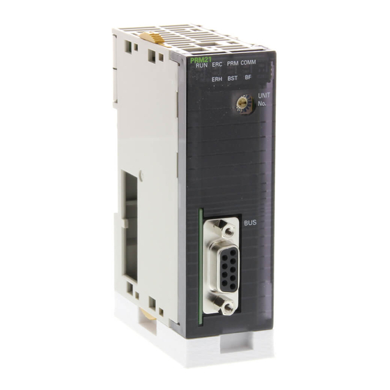
Master unit
Hide thumbs
Also See for CJ Series:
- Operation manual (278 pages) ,
- Connection manual (96 pages) ,
- Manual (38 pages)


Need help?
Do you have a question about the CJ Series and is the answer not in the manual?
Questions and answers