Table of Contents
Advertisement
Quick Links
Advertisement
Table of Contents

Subscribe to Our Youtube Channel
Related Manuals for Circutor CVM-C10


Summary of Contents for Circutor CVM-C10
- Page 1 Power analyzer CVM-C10 INSTRUCTION MANUAL (M001B01-03-21A)
- Page 2 CVM-C10 Instruction Manual...
-
Page 3: Safety Precautions
CIRCUTOR, SA reserves the right to make modifications to the device or the unit specifications set out in this instruction manual without prior notice. CIRCUTOR, SA on its web site, supplies its customers with the latest versions of the device specifica- tions and the most updated manuals. -
Page 4: Table Of Contents
3�5�1�- MEASURING THREE-PHASE NETWORKS WITH A 4-WIRE CONNECTION, CVM-C10-ITF AND CVM-C10-mV MODEL� ��������������������������������������������������������������������������������������������������������������������������������������������������������������������� 15 3�5�2�- MEASURING THREE-PHASE NETWORKS WITH A 4-WIRE CONNECTION, CVM-C10-ITF-IN MODEL� ��������� 16 3�5�3�- MEASURING THREE-PHASE NETWORKS WITH A 4-WIRE CONNECTION CVM-C10-MC MODEL� ��������������� 17 3�5�4�- MEASURING THREE-PHASE NETWORKS WITH A 4-WIRE CONNECTION CVM-C10-MC-IN MODEL� ���������� 18 3�5�5�- MEASURING THREE-PHASE NETWORKS WITH A 4-WIRE CONNECTION, CVM-C10-FLEX MODEL ������������... - Page 5 CVM-C10 4�9�4� SECONDARY CURRENT ( MODEL CVM-C10-ITF) �������������������������������������������������������������������������������������������49 4�9�5� PRIMARY NEUTRAL CURRENT ( MODELS: CVM-C10-ITF-IN AND CVM-C10-MC-IN) ����������������������������������49 4�9�6� SECUNDARY NEUTRAL CURRENT (MODEL CVM-C10-ITF-IN) ��������������������������������������������������������������������� 50 4�9�7� NUMBER OF QUADRANTS ����������������������������������������������������������������������������������������������������������������������������� 50 4�9�8� MEASUREMENT CONVENTION ��������������������������������������������������������������������������������������������������������������������� 50 4�9�9� TYPE OF INSTALLATION ��������������������������������������������������������������������������������������������������������������������������������� 51 4�9�10�...
-
Page 6: Revision Log
CVM-C10 REVISION LOG Table 1: Revision log� Date Revision Description 04/14 M001B01-03-14A Initial Version Changes in the following sections: 06/14 M001B01-03-14B 3.4 - 4.9 - 4.10 - 5 Changes in the following sections: 06/14 M001B01-03-14C 4.9.5 - 4.9.6 - 4.10.2.1... -
Page 7: 1�- Verification Upon Reception
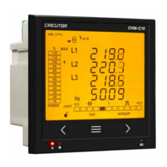
CIRCUTOR's after-sales service. 2.- PRODUCT DESCRIPTION The CVM-C10 device measures, calculates and displays the main electrical parameters of the follow- ing networks: single-phase, two-phase, with and without neutral, balanced three-phase, with ARON measurements or unbalanced. The measurement will be taken in RMS with the three AC voltage inputs and three current inputs. - Page 8 - 2 digital outputs, fully programmable. (Not available in the CVM-C10-ITF-IN, CVM-C10-MC-IN and CVM-C10-FLEX models) - 2 alarm relays, fully programmable (Not available in the CVM-C10-FLEX model) - RS-485 Communications, with two serial protocols: MODBUS RTU© and BACnet. Instruction Manual...
-
Page 9: 3�- Device Installation
The CVM-C10 device must be installed by authorised and qualified staff. The power supply plug must be disconnected and measuring systems switched off before handling, al- tering the connections or replacing the device. -
Page 10: 3�2�- Installation
The temperature rating of insulation of wires connected to the device will be at minimum 62ºC. 3�3�- CVM-C10-FLEX: ROGOWSKI SENSORS The CVM-C10-FLEX model measures currents using flexible sensors, based on the Rogowski coil prin- ciple. The flexibility of the sensor allows it to measure an alternating current irrespective of the position of the conductor. - Page 11 CVM-C10 Table 3: Probe cable terminal connections Probe cable terminal connections FLEX-MAG Shield Común / Common Canal de medida / Measuring channel Black : Shield (SHLD) Blue: Common (C) Green: Measuring channel (L1, L2, L3, N) Instruction Manual...
-
Page 12: 3�4�- Device Terminals
CVM-C10 3�4�- DEVICE TERMINALS 3�4�1�- LIST OF TERMINALS, CVM-C10-ITF, CVM-C10-MC AND CVM-C10-mV MODELS Table 4: List of terminals of the CVM-C10-ITF, CVM-C10-MC and CVM-C10-mV� Device terminals 1 : A1 Auxiliary power supply. 13: I2, digital input 2 / tariff selection 2: A2 Auxiliary power supply. -
Page 13: 3�4�2�- List Of Terminals, Cvm-C10-Itf-In And Cvm-C10-Mc-In Models
CVM-C10 3�4�2�- LIST OF TERMINALS, CVM-C10-ITF-IN AND CVM-C10-MC-IN MODELS� Table 5: List of terminals of the CVM-C10-ITF-IN and CVM-C10-MC-IN� Device terminals 1 : A1 Auxiliary power supply. 12: I2, digital input 2 / tariff selection 2: A2 Auxiliary power supply. -
Page 14: 3�4�3�- List Of Terminals, Cvm-C10-Flex Model
CVM-C10 3�4�3�- LIST OF TERMINALS, CVM-C10-FLEX MODEL Table 6: List of terminals of the CVM-C10-FLEX� Device terminals 1 : A1 Auxiliary power supply. 10: V , Voltage input L3 2: A2 Auxiliary power supply. 11: N, Neutral 3: A(+), RS485... -
Page 15: 3�5�- Connection Diagram
S0- S0+ S0+ RS485 INPUTS A(+) B(-) I1 I2 POWER SUPPLY Rc R2 R1 Tc T2 T1 Ph-Ph Ph-N 300V ~ 520V ~ P2 P1 LOAD Figure 4: Three-Phase measuring with a 4-wire connection, CVM-C10-ITF and CVM-C10-mV model� Instruction Manual... -
Page 16: Model
MODEL� Measurement system: Power Supply OUTPUTS RS485 INPUTS A(+) B(-) I1 I2 POWER SUPPLY Rc R2 R1 Ph-Ph Ph-N 300V ~ 520V ~ P2 P1 P2 S1 LOAD Figure 5: Three-Phase Measuring with a 4-wire connection, CVM-C10-ITF-IN model� Instruction Manual... -
Page 17: 3�5�3�- Measuring Three-Phase Networks With A 4-Wire Connection Cvm-C10-Mc Model
CVM-C10 3�5�3�- MEASURING THREE-PHASE NETWORKS WITH A 4-WIRE CONNECTION CVM-C10-MC MODEL� Measurement system: Power Supply OUTPUTS S0- S0+ S0+ RS485 INPUTS A(+) B(-) I1 I2 POWER SUPPLY Rc R2 R1 Tc T2 T1 Ph-Ph Ph-N 300V ~ 520V ~ P2 P1 LOAD Figure 6: Three-Phase measuring with a 4-wire connection, CVM-C10-MC model�... -
Page 18: 3�5�4�- Measuring Three-Phase Networks With A 4-Wire Connection Cvm-C10-Mc-In Model
300V ~ 520V ~ P2 P1 LOAD Figure 7: Three-Phase measuring with a 4-wire connection, CVM-C10-MC-IN model� Note: Do not connect MC current transformers to ground. The MC transformer secondary value is set to 0.250 A (fixed value) Instruction Manual... -
Page 19: 3�5�5�- Measuring Three-Phase Networks With A 4-Wire Connection, Cvm-C10-Flex Model
CVM-C10 3�5�5�- MEASURING THREE-PHASE NETWORKS WITH A 4-WIRE CONNECTION, CVM-C10-FLEX MO- Measurement system: Power Supply RS485 INPUTS A(+) B(-) I1 I2 POWER SUPPLY Ph-Ph Ph-N FLEX-MAG (100mV~ ) 300V ~ 520V ~ L1 L2 L3 LN C SHLD SHLD LOAD Figure 8: Three-Phase measuring with a 4-wire connection, CVM-C10-FLEX model�... -
Page 20: Model
INPUTS A(+) B(-) I1 I2 POWER SUPPLY Rc R2 R1 Tc T2 T1 Ph-Ph Ph-N 300V ~ 520V ~ P2 P1 P2 S1 P2 S1 LOAD Figure 9: Three-Phase measuring with a 3-wire connection, CVM-C10-ITF and CVM-C10-mV model� Instruction Manual... -
Page 21: 3�5�7�- Measuring Three-Phase Networks With A 3-Wire Connection, Cvm-C10-Mc Model
CVM-C10 3�5�7�- MEASURING THREE-PHASE NETWORKS WITH A 3-WIRE CONNECTION, CVM-C10-MC MODEL� Measurement system: Power Supply OUTPUTS S0- S0+ S0+ RS485 INPUTS A(+) B(-) I1 I2 POWER SUPPLY Rc R2 R1 Tc T2 T1 Ph-Ph Ph-N 300V ~ 520V ~ P2 P1 LOAD Figure 10: Three-Phase measuring with a 3-wire connection, CVM-C10-MC model�... -
Page 22: 3�5�8�- Measuring Three-Phase Networks With A 3-Wire Connection, Cvm-C10-Flex Model
CVM-C10 3�5�8�- MEASURING THREE-PHASE NETWORKS WITH A 3-WIRE CONNECTION, CVM-C10-FLEX MO- DEL� Measurement system: Power Supply RS485 INPUTS A(+) B(-) I1 I2 POWER SUPPLY Ph-Ph Ph-N 300V ~ 520V ~ FLEX-MAG (100mV~ ) L2 L3 LN C SHLD SHLD LOAD Figure 11: Three-Phase measuring with a 3-wire connection, CVM-C10-FLEX model�... -
Page 23: 3�5�9�- Measuring Three-Phase Networks With A 3-Wire Connection And Transformers With An Aron Connection, Cvm-C10-Itf And Cvm-C10-Mc Models
300V ~ 520V ~ P2 P1 LOAD Figure 12: Three-Phase measuring with a 3-wire connection and transformers with an ARON connection, CVM-C10-ITF and CVM- C10-MC and models� Note: Do not connect MC current transformers to ground. CVM-C10-ITF model: The transformer secondary value must be 5A or 1A CVM-C10-MC model: The MC transformer secondary value is set to 0.250 A (fixed value) -
Page 24: Cvm-C10-Mv Models
300V ~ 520V ~ P2 P1 LOAD Figure 13: Measuring Two-Phase Networks with a 3-wire connection, CVM-C10-ITF, CVM-C10-MC and CVM-C10-mV models� Note: Do not connect MC current transformers to ground. CVM-C10-ITF model: The transformer secondary value must be 5A or 1A CVM-C10-MC model: The MC transformer secondary value is set to 0.250 A (fixed value) -
Page 25: Cvm-C10-Mc-In Models
300V ~ 520V ~ P2 P1 LOAD Figure 14: Measuring Two-Phase Networks with a 3-wire connection, CVM-C10-ITF-IN and CVM-C10-MC-IN models� Note: Do not connect MC current transformers to ground. CVM-C10-ITF-IN model: The transformer secondary value must be 5A or 1A CVM-C10-MC-IN model: The MC transformer secondary value is set to 0.250 A (fixed value) -
Page 26: 3�5�12�- Measuring Two-Phase Networks With A 3-Wire Connection, Cvm-C10-Flex Model
POWER SUPPLY Ph-Ph Ph-N 300V ~ 520V ~ FLEX-MAG (100mV~ ) L2 L3 LN C SHLD SHLD LOAD Figure 15: Measuring Two-Phase Networks with a 3-wire connection, CVM-C10-FLEX model� It is mandatory connect the SHLD terminal of the probe. Instruction Manual... -
Page 27: 3�5�13�- Measuring Single-Phase Networks, Phase To Phase, With A 2-Wire Connection, Cvm-C10-Itf, Cvm-C10-Mc And Cvm-C10-Mv Models
300V ~ 520V ~ P2 P1 LOAD Figure 16: Measuring Single-Phase Networks, phase to phase, with a 2-wire connection, CVM-C10-ITF, CVM-C10-MC and CVM-C10- mV models� Note: Do not connect MC current transformers to ground. CVM-C10-ITF model: The transformer secondary value must be 5A or 1A CVM-C10-MC model: The MC transformer secondary value is set to 0.250 A (fixed value) -
Page 28: Cvm-C10-Flex Model
300V ~ 520V ~ FLEX-MAG (100mV~ ) L2 L3 LN C SHLD SHLD LOAD Figure 17: Measuring Single-Phase Networks, phase to phase, with a 2-wire connection, CVM-C10-FLEX model� It is mandatory connect the SHLD terminal of the probe. Instruction Manual... -
Page 29: 3�5�15�- Measuring Single-Phase Networks, Phase To Neutral, With A 2-Wire Connection, Cvm-C10-Itf, Cvm-C10-Mc And Cvm-C10-Mv Models
300V ~ 520V ~ P2 P1 LOAD Figure 18: Measuring Single-Phase Networks, phase to neutral, with a 2-wire connection, CVM-C10-ITF, CVM-C10-MC and CVM- C10-mV models� Note: Do not connect MC current transformers to ground. CVM-C10-ITF model: The transformer secondary value must be 5A or 1A CVM-C10-MC model: The MC transformer secondary value is set to 0.250 A (fixed value) -
Page 30: Cvm-C10-Flex Model
300V ~ 520V ~ FLEX-MAG (100mV~ ) L2 L3 LN C SHLD SHLD LOAD Figure 19: Measuring Single-Phase Networks, phase to neutral, with a 2-wire connection, CVM-C10-FLEX model� It is mandatory connect the SHLD terminal of the probe. Instruction Manual... -
Page 31: 4�- Operation
CVM-C10 4.- OPERATION The CVM-C10 is a four-quadrant power analyzer (consumption and generation). The device can operate according to three different measurement conventions: CIRCUTOR measurement convention. IEC measurement convention. IEEE measurement convention. The measurement convention is configured in the setup menu, see “4.9.8. Measurement convention”. -
Page 32: 4�1�- Measuring Parameters
P > 0 Q < 0 > Figure 22: Convenio de medida IEEE� 4�1�- MEASURING PARAMETERS The device displays the electrical parameters shown in Table 7 Table 7: Measuring parameters of the CVM-C10� Phases Total Parameter Units L1-L2-L3 Phase-neutral voltage Vph-N ... -
Page 33: 4�2�- Keyboard Functions
4�2�- KEYBOARD FUNCTIONS The CVM-C10 has 3 keys that allow you to browse between the various screens and program the de- vice. Key functions on measuring screens ( Table 8 Table 8: Key functions on measuring screens�... - Page 34 CVM-C10 Table 8 (Continuation): Key functions on measuring screens� Long keystroke Short keystroke (2 s) Browsing the different profiles Accessing the programming menu (analyzer, user, e3) Display of the Maximum Demand Active alarm information Unlocks the active alarm Key functions on harmonics screens ( Table 9 Table 9: Key functions on harmonics screens�...
-
Page 35: 4�3�- Display
Table 3 The display is divided into four areas ( Figure 23 Figure 23: CVM-C10 Display areas The area with data per phase displays the instantaneous, maximum and minimum values of each phase being measured or calculated by the device. -
Page 36: 4�3�2� Analogue Bar
CVM-C10 4�3�2� ANALOGUE BAR Figure 25: Analogue Bar The analogue bar displays two parameters: Current power of the installation in % This parameter is displayed in 12 divisions, each one represents 10%, into which the analogue bar is divided. -
Page 37: 4�4�- Led Indicators
- KEY, LED that is lit when any key is pressed. Figure 26: LED Indicators of the CVM-C10� 4�5�- OPERATION PROFILES The CVM-C10 has 3 operation profiles. The display screens will be opened for the corresponding profile: Analyzer profile, analyzer, Electrical energy efficiency profile, e ... - Page 38 CVM-C10 Use keys to browse the different screens. The inst symbol on the bottom of the screen indicates that the values being displayed are of the instantaneous type. Table 12: Analyzer profile screens� Screen Parameters (units) phase-phase Voltage L1-L2 (V...
- Page 39 CVM-C10 Table 12 (Continuation): Analyzer profile screens� Screen Parameters (units) Apparent Power L1 (M/KVA) Apparent Power L2 (M/KVA) Apparent Power L3 (M/KVA) Apparent Power III (M/KVA) The generation values are not measured when the 2 quadrant option is selected. Inductive Reactive Power L1 (M/Kvar...
- Page 40 CVM-C10 Table 12 (Continuation): Analyzer profile screens� Screen Parameters (units) Power factor L1 (PF) Power factor L2 (PF) Power factor L3 (PF) Power factor III (PF) Cos φ L1 (cos φ) Cos φ L2 (cos φ) Cos φ L3 (cos φ) Cos φ...
- Page 41 CVM-C10 Figure 29: Analyzer profile screen displaying the minimum values� Maximum Demand The device calculates the maximum demand of the following: • Current • Three-Phase Active Power. • Three-Phase Apparent Power. • Three-Phase Inductive Reactive Power • Three-Phase Capacitive Reactive Power...
-
Page 42: 4�5�2� E 3 Profile
This profile is identified with the e symbol on the bottom of the screen ( Figure 31 Figure 31: CVM-C10 screen with the e profile� The installation's consumed and generated energy are displayed on the e profile of the device. - Page 43 CVM-C10 Table 13 (Continuation): Screens of the e profile� Screen Parameters (units) Inductive Reactive Energy Tariff 1, T1 (M/Kvar Inductive Reactive Energy Tariff 2, T2 (M/Kvar Inductive Reactive Energy Tariff 3, T3 (M/Kvar Total Inductive Reactive Energy (M/Kvar Consumption and generation values Only available for the 4 quadrant option.
-
Page 44: 4�5�3� User
This profile is identified with the user symbol on the bottom of the screen ( Figure 32 Figure 32: Screen of the CVM-C10 with the user profile� This profile displays the screens selected in the programming menu ( “4.9.12. Selecting the operation profile”... -
Page 45: 4�7�- Inputs
Figure 1 and ), fully programmable, see “4.9.25. Programming alarm 3 (Digital output T1)” “4.9.26. Figure 3 Programming alarm 4 (Digital output T2)”. Note: The digital outputs are not available on models CVM-C10-ITF-IN, CVM-C10-MC-IN and CVM- C10-FLEX Instruction Manual... -
Page 46: 4�9�- Programming
CVM-C10 4�9�- PROGRAMMING From the programming menu you can: Lock the status of the menu. Define the transformation ratios. Select the number of quadrants and type of installation. Select the operation profile of the device. Program the carbon emission ratio, kgCO ... -
Page 47: 4�9�1� Primary Voltage
CVM-C10 When the desired value is shown on the screen, move onto the next digit by pressing the key modify the other values. If you press the key after changing the last digit, it will jump back to the first digit so you can modify the previously programmed values again. -
Page 48: 4�9�2� Secondary Voltage
CVM-C10 4�9�2� SECONDARY VOLTAGE On this screen the voltage transformer secondary is programmed. Press key for 3 seconds to edit the transformer secondary value. The prog icon will be displayed on the bottom of the screen. To enter or modify the value, press the key repeatedly, increasing the value of the flashing digit. -
Page 49: 4�9�4� Secondary Current ( Model Cvm-C10-Itf)
To validate the data, press Press key to access the next programming step 4�9�5� PRIMARY NEUTRAL CURRENT ( MODELS: CVM-C10-ITF-IN AND CVM-C10-MC-IN) The neutral current transformer primary is programmed on this screen. Press key for 3 seconds to edit the transformer primary value. The prog icon will be displayed on the bottom of the screen. -
Page 50: 4�9�6� Secundary Neutral Current (Model Cvm-C10-Itf-In)
CVM-C10 4�9�6� SECUNDARY NEUTRAL CURRENT (MODEL CVM-C10-ITF-IN) The neutral current transformer secundary is programmed on this screen. Press key for 3 seconds to edit the transformer secundary value. The prog icon will be displayed on the bottom of the screen. -
Page 51: 4�9�9� Type Of Installation
CVM-C10 Press key to access the next programming step. 4�9�9� TYPE OF INSTALLATION The type of installation is selected on this screen. Press key for 3 seconds to edit the type of installation. The prog icon will be displayed on the bottom of the screen. -
Page 52: 4�9�11� Deleting Maximum Demand
CVM-C10 Note: Programming the value 0 disables the calculation of the maximum demand. Press key to access the next programming step. 4�9�11� DELETING MAXIMUM DEMAND On this screen you select whether or not to delete the maximum demand. Press key for 3 seconds to edit the deletion selection. -
Page 53: 4�9�13� Backlight, Turning On The Backlit Display
CVM-C10 the display screens are those that were stored in previous programming settings of the device. (In the case of new devices, these will be the same as those of the analyzer profile) , the display screens are selected. To validate the data, press for 3 seconds and the prog icon will disappear from the display. -
Page 54: 4�9�14� Selecting The Cos Φ - Pf Bar On The Display
CVM-C10 To validate the data, press for 3 seconds and the prog icon will disappear from the display. Maximum programming value: 99 seconds. Minimum programming value: 0 seconds. Note: The value 00 indicates that the backlight will stay permanently lit. -
Page 55: 4�9�17� Selecting The Range Of Energies
CVM-C10 for 3 seconds and the prog icon will disappear from the display. To validate the data, press Press key to access the next programming step. 4�9�17� SELECTING THE RANGE OF ENERGIES The operation of the range of energy is selected on this screen. -
Page 56: Carbon Emission Ratio Of Generated Energy
CVM-C10 4�9�19� kgC0 CARBON EMISSION RATIO OF GENERATED ENERGY The carbon emissions ratio is the amount of emissions released into the atmosphere to produce a unit of electricity (1 kWh). The ratio for the European mix is approximately 0.65 kgCO per kWh. -
Page 57: 4�9�21� Cost Ratio Of Generated Energy
CVM-C10 If you press the key after changing the last digit, it will jump back to the first digit so you can modify the previously programmed values again. Press key to browse the different tariffs. for 3 seconds and the prog icon will disappear from the display. -
Page 58: 4�9�22� Cost Ratio Of Consumed Energy
Press key to access the next programming step. 4�9�23� PROGRAMMING ALARM 1 (RELAY 1) Note: Configuration parameters not available for the CVM-C10-FLEX model. The variable code is selected on this screen, depending on Table 15, which will control alarm relay 1. - Page 59 CVM-C10 If you press the key after changing the last digit, it will jump back to the first digit so you can modify the previously programmed values again. To validate the data, press for 3 seconds and the prog icon will disappear from the display.
- Page 60 CVM-C10 Programming the maximum value The maximum value: the alarm is activated when this value is exceeded. Press key for 3 seconds to edit the maximum value selection. The prog icon will be displayed on the bottom of the screen.
- Page 61 CVM-C10 Programming the minimum value The minimum value: the alarm is activated below this value. Press key for 3 seconds to edit the minimum value selection. The prog icon will be displayed on the bottom of the screen. To enter or modify the value, press the key repeatedly, increasing the value of the flashing digit.
- Page 62 CVM-C10 Programming the hysteresis value The hysteresis value, i.e., difference between the alarm connection and disconnection value, in %, is programmed on this screen. Press key for 3 seconds to edit the hysteresis value selection. The prog icon will be displayed on the bottom of the screen.
-
Page 63: 4�9�24� Programming Alarm 2 (Relay 2)
“4.9.23. Programming alarm 1 (Relay 1)” 4�9�25� PROGRAMMING ALARM 3 (DIGITAL OUTPUT T1) Note: Configuration parameters not available for the CVM-C10-FLEX, CVM-C10-ITF-IN and CVM-C10- MC-IN models. All values for digital output T1 are programmed on this screen. The variable code is selected on this screen, depending on Table 15 which will control digital output T1. - Page 64 CVM-C10 for 3 seconds to edit the code selection. The prog icon will be displayed on the bottom Press key of the screen. To enter or modify the value, press the key repeatedly, increasing the value of the flashing digit.
- Page 65 CVM-C10 Programming kilowatts per pulse Press key for 3 seconds to edit the kilowatts per pulse selection. The prog icon will be displayed on the bottom of the screen. To enter or modify the value, press the key repeatedly, increasing the value of the flashing digit.
-
Page 66: 4�9�26� Programming Alarm 4 (Digital Output T2)
Maximum programming value: 500 ms. Minimum programming value: 30 ms. 4�9�26� PROGRAMMING ALARM 4 (DIGITAL OUTPUT T2) Note: Configuration parameters not available for the CVM-C10-FLEX, CVM-C10-ITF-IN and CVM-C10- MC-IN models. All values for digital output T2 are programmed on this screen. -
Page 67: 4�9�29� Rs-485 Communications: Protocol
CVM-C10 4�9�29� RS-485 COMMUNICATIONS: PROTOCOL The RS-485 communications protocol is selected on this screen. Press the key for 3 seconds to edit the function selection. The prog icon will be displayed on the bottom of the screen. Press key to browse the two options:... - Page 68 CVM-C10 for 3 seconds and the prog icon will disappear from the display. To validate the data, press Press key to access the next programming step. Parity The type of parity of Modbus communications is selected on this screen.
- Page 69 CVM-C10 4�9�29�2 BACnet protocol Note: Protocol available in devices with version 3.00 or higher. Transmission speed The transmission speed of BACnet communications is programmed on this screen. Press key for 3 seconds to edit the transmission speed selection. The prog icon will be displayed on the bottom of the screen.
-
Page 70: 4�9�30� Locking The Programming
CVM-C10 When the desired value is shown on the screen, press the key to go to the next digit and modify the other values. If you press the key after changing the last digit, it will jump back to the first digit so you can modify the previously programmed values again. - Page 71 CVM-C10 To validate the data, press for 3 seconds and the prog icon will disappear from the display. Default password: 1234. This value may only be modified through communications. See “4.10.3.8.17. Password configuration.” Press the key to exit the setup menu.
-
Page 72: 4�10�- Communications
CVM-C10 and the master device of 1200 metres. A maximum of 32 CVM-C10 devices can be connected to this bus. Use an intelligent RS-232 to RS-485 network protocol converter to establish the communications with the master device. -
Page 73: 4�10�2� Protocol
CVM-C10 4�10�2� PROTOCOL In the Modbus protocol, the CVM-C10 device uses the RTU (Remote Terminal Unit) mode. The Modbus functions implemented in the device are as follows: Function 0x03 and 0x04: Reading integer logs. Function 0x05: Writing a relay. Function 0x10: Writing multiple logs. -
Page 74: 4�10�3� Modbus Commands
CVM-C10 Response: Initial Address Function Value Register 0834 FF00 CEEF 4�10�3� MODBUS COMMANDS 4�10�3�1� Measurement variables� All the adresses of Modbus memory are in Hexadecimal. For these variables is implemented the Function 0x03 and 0x04� Table 19: Modbus memory map (Table 1) - Page 75 CVM-C10 Table 19 (Continuation): Modbus memory map (Table 1) Parameter Symbol Instantaneous Maximum Minimum Units L3-L1 Voltage 42-43 148-149 1A6-1A7 V x 10 Neutral Current N 44-45 14A-14B 1A8-1A9 L1 voltage % THD %THDV1 46-47 14C-14D 1AA-1AB % x 10...
- Page 76 CVM-C10 Table 20 (Continuation): Modbus memory map (Table 2) Parameter Symbol Tariff 1 Tariff 2 Tariff 3 Total Units Generated capacitive reactive energy kvarhC III 7C-7D A6-A7 D0-D1 FA-FB varh (varhC) Generated apparent energy (kVAh) kVAh III 7E-7F A8-A9 D2-D3...
- Page 77 CVM-C10 Table 21 (Continuation) : Modbus memory map (Table 3)� Parameter L1 Voltage L2 Voltage L3 Voltage Units 31st Order harmonic % x 10 Table 22: Modbus memory map (Table 4)� Parameter L1 Current L2 Current L3 Current Units Fundamental Harm.
- Page 78 CVM-C10 Table 23: Modbus memory map: Deleting parameters� Parameters Address Valid data margin FF00 Deleting energies FF00 Deleting maximum and minimum values Starting maximum demand FF00 Deleting the hour counters (All tariffs) FF00 Deleting the maximum value of the maximum demand...
- Page 79 Neutral current secondary 271B 5: ../5 A All variables must be programmed at the same time. This variable is only programmed for the CVM-C10-ITF-IN model. 4�10�3�8�3� Number of quadrants Table 30: Modbus memory map: Number of quadrants Maximum demand Default...
- Page 80 CVM-C10 4�10�3�8�5� Type of installation Table 32: Modbus memory map: Type of installation Type of installation Default Configuration variable Address Valid data margin value Three-phase network with 4 wires� Three-phase network with 3 wires. Three-phase network with 3 wires, Aron.
- Page 81 They have 1 decimal place. (10) 4�10�3�8�12� Programming alarms 1 and 2 (Relays 1 and 2) Note: Configuration parameters not available for the CVM-C10-FLEX model. Table 39: Modbus memory map: Programming alarms 1 and 2� Programming alarms 1 and 2...
- Page 82 CVM-C10 4�10�3�8�13� Programming alarms 3 and 4 (Digital outputs T1 and T2) Note: Configuration parameters not available for the CVM-C10-FLEX , CVM-C10-ITF-IN and CVM-C10- MC-IN models. Table 40: Modbus memory map: Programming alarms 3 and 4� Programming alarms 3 and 4...
- Page 83 CVM-C10 Table 45: Variable format: Status of the digital outputs� Bit 7 Bit 6 Bit 5 Bit 4 Bit 3 Bit 2 Bit 1 Bit 0 Output 4 Output 3 Output 2 Output 1 0: OFF 0: OFF 0: OFF...
-
Page 84: 4�10�4� Bacnet Protocol
CVM-C10 4�10�4� BACnet PROTOCOL BACnet is a communications protocol for Building Automation and Control NETworks. This protocol replaces the proprietary communications of each device, making it a set of common communication rules that enables the complete integration of the building automation and control devices of different manufacturers. -
Page 85: 4�10�5� Mapa Pics
CVM-C10 4�10�5� MAPA PICS PICS Vendor Name: CIRCUTOR Product Name: CVM-C10 Product Model Number: 0116 Application Software Version: 1.0 Firmware Revision: 0.7.1 BACnet Protocol Revision: Product Description: Electrical energy meter BACnet Standardized Device Profile (Annex L) BACnet Application Specific Controller (B-ASC) - Page 86 CVM-C10 DESCRIPTION SYMBOL ID OBJECTS OBJECT NAME UNITS Potencia reactiva Reactive power kvar 2 ReactPwrPh2 kvar Factor de potencia Power factor PF 2 PwrFactPh2 Tensión fase-neutro Voltage phase to neutral AI10 Ph2NU3 Corriente Current AI11 Ph3Current Potencia activa Active power...
- Page 87 CVM-C10 DESCRIPTION SYMBOL ID OBJECTS OBJECT NAME UNITS Máxima demanda I1 Maximum demand I1 Md (A1) AI44 MaxDemand_A1 Máxima demanda I2 Maximum demand I2 Md(A2) AI45 MaxDemand_A2 Máxima demanda I3 Maximum demand I3 Md(A3) AI46 MaxDemand_A3 Máxima demanda A Maximum demand A...
-
Page 88: 5�- Technical Features
CVM-C10 5.- TECHNICAL FEATURES AC Power supply Rated voltage 95 ... 240 V ± 10% Frequency 50 ... 60 Hz Consumption 4 ... 6 VA Installation category CAT III 300 V DC Power supply Rated voltage 105 ... 272 V ±... - Page 89 Maximum current 50 mA Maximum frequency 16 impulses / sec Pulse width 30 ms to 500 ms (Programmable) Relay outputs (CVM-C10-ITF, CVM-C10-ITF-IN, CVM-C10-MC, CVM-C10-MC-IN, CVM-C10-mV ) (19) Quantity Max� voltage open contacts 250 V ~ Maximum current Maximum switching power...
- Page 90 5 ... 95% Maximum altitude 2000 m IP21 Protection degree (20) Front panel: IP51 (IP64 with accessory) Environmental features (CVM-C10-MC, CVM-C10-MC-IN, CVM-C10-mV and CVM-C10-FLEX) Operating temperature -5ºC ... +45ºC Storage temperature -10ºC ... +50ºC Relative humidity (non-condensing) 5 ... 95%...
- Page 91 Electromagnetic compatibility (EMC)� Generic standards� Emission standard BS EN 61000-6-4 for industrial environments Safety requirements for electrical equipment for measurement, control, and UL/CSA 61010-1 3rd edition laboratory use - Part 1: General requirements 60.9 96.7 10.9 Figure 35: Dimensions of the CVM-C10� Instruction Manual...
-
Page 92: 6�- Maintenance And Technical Service
CVM-C10 6.- MAINTENANCE AND TECHNICAL SERVICE In the case of any query in relation to device operation or malfunction, please contact the CIRCUTOR, SA Technical Support Service. Technical Assistance Service Vial Sant Jordi, s/n, 08232 - Viladecavalls (Barcelona) Tel: 902 449 459 ( España) / +34 937 452 919 (outside of Spain) email: sat@circutor.com... -
Page 93: 8�- Ce Certificate
CVM-C10 8.- CE CERTIFICATE Instruction Manual... - Page 94 CVM-C10 Instruction Manual...
- Page 95 CVM-C10 Instruction Manual...
- Page 96 CIRCUTOR, SA Vial Sant Jordi, s/n 08232 -Viladecavalls (Barcelona) Tel.: (+34) 93 745 29 00 - Fax: (+34) 93 745 29 14 www.circutor.com central@circutor.com...
Need help?
Do you have a question about the CVM-C10 and is the answer not in the manual?
Questions and answers