
Related Manuals for Circutor CVM-144 (HAR)


Summary of Contents for Circutor CVM-144 (HAR)
- Page 1 SUPPLY NETWORK ANALYZER CVM-144 (HAR) SERIES (Harmonics) INSTRUCTION MANUAL ( M98170501-03 / 04A ) CIRCUTOR S.A.
-
Page 2: Table Of Contents
-- Supply network analyzer CVM-144 (HAR) ----- User's manual --- Page No. 1 CONTENTS page DELIVERY SPOT CHECK ......................2 MAIN FEATURES........................3 MODELS............................5 INSTALLATION AND START-UP ....................6 4.1.- Installation........................6 4.2.- CVM-144 connection terminal arrangement (power supply connection terminal) ......8 4.3.- CVM-144 connection terminal arrangement (Expansion card) ........9 4.4.- Connection drawing for the CVM-144 : ...............14 OPERATION MODE........................18 SET-UP PROCEDURE ......................20... -
Page 3: Delivery Spot Check
-- Supply network analyzer CVM-144 (HAR) ----- User's manual --- Page No. 2 1.- DELIVERY SPOT CHECK This manual is issued to help all the CVM-144 users to install and use it in order get the best from it. After receiving the unit, please check the following points: (a) Does this device correspond to your order specifications? (b) Check if any damage was done during the shipment process. -
Page 4: Main Features
-- Supply network analyzer CVM-144 (HAR) ----- User's manual --- Page No. 3 2.- MAIN FEATURES The CVM-144 power meter is a programmable measuring instrument, offering several operation possibilities selectable in its SET-UP option. Before power supplying the instrument, read the CONNECTIONS and SET-UP sections and choose the most suitable operation mode for getting your desired data. - Page 5 -- Supply network analyzer CVM-144 (HAR) ----- User's manual --- Page No. 4 By means of an internal microprocessor it simultaneously measures: Parameter Symbol L1 L2 L3 Average Voltage (phase-neutral) Voltage (phase-phase) Current Frequency Active power Reactive power L kvarL Reactive power C kvarL /(-C) Apparent power...
-
Page 6: Models
-- Supply network analyzer CVM-144 (HAR) ----- User's manual --- Page No. 5 3.- MODELS Current Model measurement CVM-144 Shunts CVM-144-ITF Isolated ITF Code Expansion modules Card 7 70 570 Mod. CVM 144 C2 7 70 571 Mod. CVM 144 C2 Analogue 0571 3* 1* 7 70 572 Mod. -
Page 7: Installation And Start-Up
-- Supply network analyzer CVM-144 (HAR) ----- User's manual --- Page No. 6 4.- INSTALLATION AND START-UP The manual you hold in your hands contains information and warnings that the user should respect in order to guarantee a proper operation of all the instrument functions and keep its safety conditions. - Page 8 -- Supply network analyzer CVM-144 (HAR) ----- User's manual --- Page No. 7 b.-Maximum voltage at the voltage measuring circuit: Standard : 300 V a.c. phase-to-neutral/520 V a.c. phase-to-phase 45 to 65 Hz Other models on request : CVM-144-measuring 500 V: 500 Va.c. phase-to-neutral/866 Va.c. phase-to-phase CVM-144-measuring 110 V: 110 Va.c.
-
Page 9: Cvm-144 Connection Terminal Arrangement (Power Supply Connection Terminal)
-- Supply network analyzer CVM-144 (HAR) ----- User's manual --- Page No. 8 4.2.- CVM-144 connection terminal arrangement (power supply connection terminal) (see lable on the rear part) 300 V 230 V 300V 520V Power Supply No. Terminal description No. Terminal description *Power supply AL1 IL3 S2 Current measurement *Power supply AL2... -
Page 10: Cvm-144 Connection Terminal Arrangement (Expansion Card)
-- Supply network analyzer CVM-144 (HAR) ----- User's manual --- Page No. 9 4.3.- CVM-144 connection terminal arrangement (Expansion card) (see lable on the rear part) 4.3.1.- Basic card (770 570, 770 573 and 770 576) Description Card connection terminal arrangement Mod CVM 144 -C2 (Code: 7 70 570) Mod CVM 144 RS485-C2... - Page 11 -- Supply network analyzer CVM-144 (HAR) ----- User's manual --- Page No. 10 4.3.2.- Card for analog Inputs/Outputs (7 70 571, 7 70574 and 7 70577) Description Card connection terminal arrangement Mod CVM 144 -C2-Analogue (Code: 7 70 571) Mod CVM 144 RS485-C2-Analogue (Code: 7 70 574) Mod CVM 144 RS232-C2-Analogue (Code: 7 70 577)
- Page 12 -- Supply network analyzer CVM-144 (HAR) ----- User's manual --- Page No. 11 4.3.3.- Module for residual and neutral currents (770 572, 770 575 and 770578) Description Lable in the expansion module connection terminal Mod CVM 144 -C2-Currents R L 2 R L 1 (Code: 7 70 572) 2 5 0 V...
- Page 13 -- Supply network analyzer CVM-144 (HAR) ----- User's manual --- Page No. 12 • Connection diagram of the WG transformer (for residual current purposes) One single WG series transformer can be use for the measurement of residual currents within the range to 3 A or to 30 A, jut depending on the arranged connection diagram.
- Page 14 -- Supply network analyzer CVM-144 (HAR) ----- User's manual --- Page No. 13 4.3.4.- Card for digital Inputs (7 70 579 and 7 70580) Description Card connection terminal arrangement Mod CVM 144 -C2-Digital (Code: 770 569) Mod CVM 144 RS485-C2-Digital (Code: 7 70 579) Mod CVM 144 RS232-C2-Digital (Code: 7 70 580)
-
Page 15: Connection Drawing For The Cvm-144
-- Supply network analyzer CVM-144 (HAR) ----- User's manual --- Page No. 14 4.4.- Connection drawing for the CVM-144 : a.- Three-phase network.- 4 wires (low voltage) : 9 10 11 12 A.C. POWER SUPPLY PowerSupply (SDC Model) Terminal Description + V d.c. - Page 16 -- Supply network analyzer CVM-144 (HAR) ----- User's manual --- Page No. 15 b.-Three-phase network – 3 wires (low voltage): 9 10 11 12 A.C. POWER SUPPLY PowerSupply (SDC Model) Terminal Description + V d.c. - V d.c.
- Page 17 -- Supply network analyzer CVM-144 (HAR) ----- User's manual --- Page No. 16 c.- Three-phase network - 3 wires (2 P.T. and 3 C.T.): 9 10 11 12 A.C. POWER SUPPLY PowerSupply (SDC Model) Terminal Description + V d.c. - V d.c.
- Page 18 -- Supply network analyzer CVM-144 (HAR) ----- User's manual --- Page No. 17 d.- Three-phase network - 3 wires (2 P.T. and 2 C.T.): 9 10 11 12 A.C. POWER SUPPLY PowerSupply (SDC Model) Terminal Description + V d.c. - V d.c. IMPORTANT REMARK! If power = -0.01 is shown for any of the phases (codes 03, 09 and 15) and voltage and current are not zero for this phase, check out following points:...
-
Page 19: Operation Mode
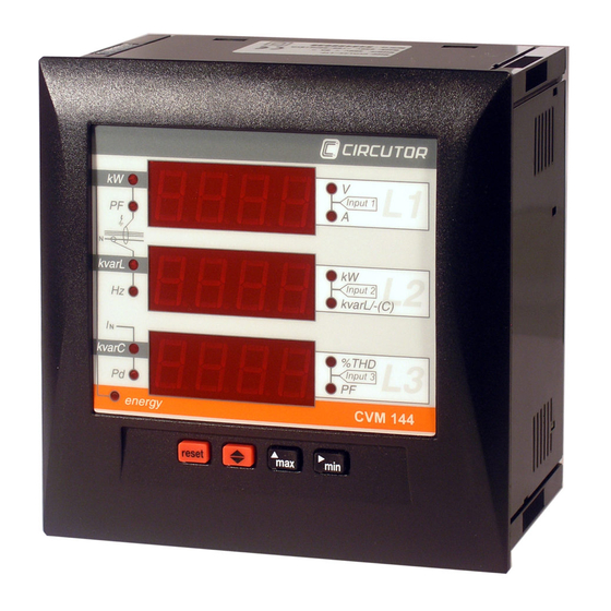
-- Supply network analyzer CVM-144 (HAR) ----- User's manual --- Page No. 18 5.- OPERATION MODE The instrument has three displays. Each one has also a LED type indicators (red colour). Every led will be on according to the parameter presently shown in screen. - Page 20 -- Supply network analyzer CVM-144 (HAR) ----- User's manual --- Page No. 19 Pressing the "max" or "min" key, maximum or minimum values for the parameters being shown by display, respectively, appear in screen. This function is only valid while you keep pressing the "max" or "min" key. If you stop pressing the key the instantaneous values will appear again after 5 seconds.
-
Page 21: Set-Up Procedure
-- Supply network analyzer CVM-144 (HAR) ----- User's manual --- Page No. 20 6.- SET-UP PROCEDURE The set-up procedure of the CVM-144 is performed by means of several SET- UP options. For accessing the set-up menu the keys max & min must be simultaneously pressed once the instrument is at the main screen. -
Page 22: Phase-To-Phase Or Phase-To-Neutral Voltages
-- Supply network analyzer CVM-144 (HAR) ----- User's manual --- Page No. 21 6.1.- Phase-to-Phase or Phase-to-Neutral voltages After the word "set" you will see on the three displays the voltages of the phases L1, L2, L3. Phase to Neutral Voltages: U1, U2, U3 Phase to Phase Voltages : U12, U23, U31... -
Page 23: Voltage Transformation Ratio
-- Supply network analyzer CVM-144 (HAR) ----- User's manual --- Page No. 22 6.3.- Voltage transformation ratio 6.3.1.- Voltage Transformer Primary On the screen we read the word "SET U P" followed by 5 digits. They allow us setting the primary of the voltage transformer. SET U P - - - - -... -
Page 24: Current Transformer Primary
-- Supply network analyzer CVM-144 (HAR) ----- User's manual --- Page No. 23 6.3.2.- Voltage Transformer Secondary We can now set the value of the secondary of the voltage transformer. Only three digits are available: SET U - - - Same process than in point 6.2.-: "max"... -
Page 25: Transformation Ratio For The Measurement Of Neutral And Residual Current
-- Supply network analyzer CVM-144 (HAR) ----- User's manual --- Page No. 24 NOTES: The secondary of the current transformers is not programmable. It is automatically set at 5 A (... / 5 A ac) The primary current value to be set is also limited by the following condition: The maximum allowable primary current value which can be set is defined by the fact that the multiplication of the primary voltage value by this primary current value cannot exceed 20,000,000. - Page 26 -- Supply network analyzer CVM-144 (HAR) ----- User's manual --- Page No. 25 6.5.2.- Residual current measuring range: 3 A or 30 A You will view in screen the message "SET A_L". Set then the right measuring range of the residual current input to which the WG transformer has been connected..
-
Page 27: Setting Power Demand Utility Screens
-- Supply network analyzer CVM-144 (HAR) ----- User's manual --- Page No. 26 6.6.- Setting power demand utility screens. Push the key " " and the following screens will appear by display: 1.- PARAMETER TO CONTROL ("Pd Code xx") None Three phase active power kW III Three phase apparent power... -
Page 28: Initial Screen Setting
-- Supply network analyzer CVM-144 (HAR) ----- User's manual --- Page No. 27 6.7.- Initial screen setting This option allows choice among fixed or rotary screen: a) Fixed screen (choice is switch just pressing ): choice the initial screen to be shown when the CVM-144 is powered (or when the CVM-144 is reset). -
Page 29: Clearing Energy Counters
-- Supply network analyzer CVM-144 (HAR) ----- User's manual --- Page No. 28 6.9.- Clearing energy counters On display we see "CLR ENER no" (Clear energy counters). - "max": To select "YES" or "no" - " ": To validate the choice and pass to the following set-up option. Display: If any of the energies is programmed (kWh, kvarhL or kvarhC), it is displayed as follows:... -
Page 30: Thd Or D Setting
-- Supply network analyzer CVM-144 (HAR) ----- User's manual --- Page No. 29 6.10.- THD or D setting dHAR dHAR Two modes for the harmonic distortion calculation can be selected: a) d % : total value of the harmonic distortion referred to the fundamental value. b) Thd % : total value of the harmonic distortion referred to the R.M.S. -
Page 31: Additional Screens When Relay Outputs (2 Relays) Are Equipped
-- Supply network analyzer CVM-144 (HAR) ----- User's manual --- Page No. 30 6.11.- Additional screens when RELAY OUTPUTS (2 relays) are equipped With these outputs the CVM-144...C2 can be set to deliver: A.- Pulse every certain kWh or kvarh (ENERGY). You can define the value corresponding to the energy consumed for generating a pulse (0.5 s long): kWh / 1 pulse or kvarh / 1 pulse B.- ALARM conditions: the parameter to be controlled, the maximum value,... - Page 32 -- Supply network analyzer CVM-144 (HAR) ----- User's manual --- Page No. 31 Parameter Symbol Code Parameter Symbol Code Three-phase active power kW III Three-phase cos ϕ Cos ϕ Three-phase inductive power kvarL III Three-phase power factor PF III Three-phase capacitive power kvarC III Frequency Active energy...
- Page 33 -- Supply network analyzer CVM-144 (HAR) ----- User's manual --- Page No. 32 a.- If an ENERGY parameter is chosen: kWh (31), kvarhL (32) or kvarhC(33) OUT 1 RELAY 1 PULS xxxx kW / pulse (1) Value of energy in kW : four digits with floating decimal point Set-up procedure: "max"...
- Page 34 -- Supply network analyzer CVM-144 (HAR) ----- User's manual --- Page No. 33 - For accessing to the next option, press " ": set-up options for the second relay will appear. OUT 2 RELAY 2 CODE Parameter value (2) Act as before. Pressing again " "...
- Page 35 -- Supply network analyzer CVM-144 (HAR) ----- User's manual --- Page No. 34 b.2.- Programming the minimum value to be controlled: OUT 1 RELAY 1 AL LO 0.000 Minimum value b.3.- Programming the delay: OUT 1 RELAY 1 Delay in seconds 0.000 maximum 9999 s - Press "...
- Page 36 -- Supply network analyzer CVM-144 (HAR) ----- User's manual --- Page No. 35 ALARM ACTIVATION: Alarms operation depend on the set values of MAXIMUM and MINIMUM. MIN + MAX + ====== max > min MIN + MAX + max < min ============== MIN -- MAX +...
- Page 37 -- Supply network analyzer CVM-144 (HAR) ----- User's manual --- Page No. 36 The DELAY set value is applied either to the connection or the disconnection when the alarm conditions occur. User-definable units for the different parameters are: Parameter Format Example Voltage 220.5 = 220.5 V...
-
Page 38: Additional Screens With 4 - 20 Ma Outputs Y Inputs
-- Supply network analyzer CVM-144 (HAR) ----- User's manual --- Page No. 37 6.12.- Additional screens with 4 - 20 mA outputs y inputs CVM-144 equipped with an “Analogue” type module provides 4 - 20 mA d.c. or 0 - 20 mA d.c. inputs and outputs (inputs can also optionally be 0-10 V type). 6.12.1.- Additional screen with the 4 - 20 mA output These can be programmed to obtain an output signal proportional to any of the parameters measured by the CVM-144, including the ability of setting the scale... - Page 39 -- Supply network analyzer CVM-144 (HAR) ----- User's manual --- Page No. 38 c.- Scale offset: Value of the parameter that we assign as the zero of the scale. dA 1 OUTPUT D/A Nr.1 Zero zero of the scale: x.xxx allows choosing the zero of the scale (four digits with floating decimal point) "max"...
- Page 40 -- Supply network analyzer CVM-144 (HAR) ----- User's manual --- Page No. 39 For passing to the next option, press "display": the setup for the second output will only if this output is available appear ( dA 2 OUTPUT D/A Nr.2 code xxxx Proceed as in the previous sections.
- Page 41 -- Supply network analyzer CVM-144 (HAR) ----- User's manual --- Page No. 40 6.12.2.- Additional screens with 4 - 20 mA inputs The 4-20 mA analog inputs (which can also be optionally 0-10 V type) can be set to obtain the processed signal either by display or through communications. To complete the analog inputs management, the user must program the scale values (offset and full-scale value).
- Page 42 -- Supply network analyzer CVM-144 (HAR) ----- User's manual --- Page No. 41 c.- Scale offset: Value of the parameter that we assign as the zero of the scale. In 1 INPUT A/D Nr.1 Zero zero of the scale: x.xxx allows choosing the zero of the scale (four digits with floating decimal point) "max"...
-
Page 43: Specifications
-- Supply network analyzer CVM-144 (HAR) ----- User's manual --- Page No. 42 7.- SPECIFICATIONS Power supply : see specifications on the rear part of the CVM-144 - CVM-144 Single-phase 230 V a.c. Voltage tolerance: +10 % / -15 % Frequency: 50 ... - Page 44 -- Supply network analyzer CVM-144 (HAR) ----- User's manual --- Page No. 43 Relays characteristics: according to model - Maximum switching load 750 VA - Maximum switching voltage 250 V a.c. - Maximum switching current 3 A (Resistive) - Mechanical endurance 3 x 10 operations - Energy / alarms pulses...
-
Page 45: Safety Considerations
10.- TECHNICAL SERVICE For any inquiry about the instrument performance or whether any failure happens, contact to CIRCUTOR’s technical service. CIRCUTOR S.A. - After-sales service Vial Sant Jordi, s/n 08232 – Viladecavalls (SPAIN) Tel - + 34 93 745 29 00 fax - + 34 93 745 29 14 E-mail : central@circutor.es... -
Page 46: Cvm-144 Communications
-- Supply network analyzer CVM-144 (HAR) ----- User's manual --- Page No. 45 11.- CVM-144 COMMUNICATIONS ---- One or some CVM-144... can be connected to a P.C.. With this system we can get all the parameters in one central point of reading. The CVM-144..., has a serial RS-485 or RS-232 type output (according to the model). -
Page 47: Rs-485 Type Connection To A Rs-232 Type Input Of A Pc
-- Supply network analyzer CVM-144 (HAR) ----- User's manual --- Page No. 46 11.2.- RS-485 type connection to a RS-232 type input of a PC DB-9 RS-232 CONVERTER RS-232 / RS-485 RS-485 CVM-144 20 ( + ) CVM-144 19 ( - ) 18 GND *If the RS485/232 converter with RTS control ability (code 770208) is used, then the pin 7 connection in the 232 side is not necessary to be done. -
Page 48: Rs-232 Type Connection To A Rs-232 Type Input Of A Pc
-- Supply network analyzer CVM-144 (HAR) ----- User's manual --- Page No. 47 11.3.- RS-232 type connection to a RS-232 type input of a PC DB-9 DB-9 RS-232 RS-232 CVM-144 20 Tx CVM-144 CVM-96 19 Rx 18 GND... -
Page 49: Modbus © Protocol
-- Supply network analyzer CVM-144 (HAR) ----- User's manual --- Page No. 48 11.4.- MODBUS © protocol The CVM-144 analyzer can communicate by means of the MODBUS © protocol, as it is following described: When the CVM-144 communicates with MODBUS protocol, it uses the RTU mode (Remote Terminal Unit ). - Page 50 -- Supply network analyzer CVM-144 (HAR) ----- User's manual --- Page No. 49 a.- Registers assigned to different parameters measured by the CVM-144: MODBUS REGISTERS (longs) HEXA-DECIMAL PARAMETER Units PRESENT MAXIMUM MINIMUM Value Value Value Phase voltage - V 1 V x 10 00-01 60-61...
- Page 51 -- Supply network analyzer CVM-144 (HAR) ----- User's manual --- Page No. 50 MODBUS REGISTERS (longs) HEXA-DECIMAL PARAMETER Units PRESENT MAXIMUM MINIMUM Value Value Value Frequency (L1) - Hz Hz x 10 28-29 88-89 E8-E9 Line voltage L1-L2 - V12 V x 10 2A-2B 8A-8B...
- Page 52 -- Supply network analyzer CVM-144 (HAR) ----- User's manual --- Page No. 51 MODBUS REGISTERS PARAMETER Units (longs) HEXA-DECIMAL Fundamental 1F4-1F5 212-213 230-231 Harmonic 2 1F6-1F7 214-215 232-233 Harmonic 3 1F8-1F9 216-217 234-235 Harmonic 4 1FA-1FB 218-219 236-237 Harmonic 5 1FC-1FD 21A-21B 238-239...
- Page 53 -- Supply network analyzer CVM-144 (HAR) ----- User's manual --- Page No. 52 EXAMPLE INQUIRY 0A 04 00 00 00 0A 71 76 CVM-144 peripheral number, 10 in decimal Reading function 00 00 Initial address (first register) 00 0A Number of registers to be read 7176 CRC character ANSWER...
- Page 54 -- Supply network analyzer CVM-144 (HAR) ----- User's manual --- Page No. 53 b.- Reading of digital inputs and outputs Inquiry Answer Relay outputs Digital inputs PP0100000008 CRC PP0100100004 CRC PP0101XXCRC Where: PP peripheral No. XX (hexadecimal byte) translated to binary b7 b6 b5 b4 b3 b2 b1 b0 Relay outputs Digital inputs...
-
Page 55: Appendix A: Second Set-Up Of The Cvm-144
-- Supply network analyzer CVM-144 (HAR) ----- User's manual --- Page No. 54 12.- APPENDIX A: Second SET-UP of the CVM-144 A second SET-UP menu is accessible in order to perform the configuration of the CVM-144 with other features different from factory-supplied ones. To access this menu proceed as follows: Being the CVM-144 powered off, simultaneously press "... -
Page 56: Set-Up Locking Or Unlocking
-- Supply network analyzer CVM-144 (HAR) ----- User's manual --- Page No. 55 b.- SETTING COMMUNICATION PARAMETERS Cdef Default configuration "max" key to switch from NO / YES • If YES is chosen: the configuration is 001 / 9600 / 8 bits / N / 1 bit •... -
Page 57: Appendix B: Insertion Of An Expansion Module Into A Cvm-144 Unit
-- Supply network analyzer CVM-144 (HAR) ----- User's manual --- Page No. 56 13.- APPENDIX B: Insertion of an expansion module into a CVM-144 unit The installation of an extension card into a CVM-144 unit must be accomplished just following below enumerated steps: Checking the card acknowledgement 1. - Page 58 -- Supply network analyzer CVM-144 (HAR) ----- User's manual --- Page No. 57 Insertion of a new module 6. Place the expansion card into the side rail (The 2 one from the top) checking that the components keep under the card. 7.
Need help?
Do you have a question about the CVM-144 (HAR) and is the answer not in the manual?
Questions and answers
Здравствуйте! Будьте добры ответьте на вопрос: регистрация аномалий напряжения осуществляется этим прибором с каким минимальным разрешением?
The minimum resolution for voltage anomaly registration with the Circutor CVM-144 (HAR) device is 4000 points (12 bits).
This answer is automatically generated
dobrý deń , je plnohodnotná náhrada za merací pristroj CVM-144 merací pristroj CVM-B150 alebo mi viete odporučiť iný merací prístroj? dakujem