Table of Contents
Advertisement
Quick Links
Advertisement
Table of Contents
Troubleshooting

Related Manuals for ZOLL M2


Summary of Contents for ZOLL M2
- Page 1 ZOLL M2 Operator’s Guide ™ 9650-000860-01 Rev. C...
- Page 2 The issue date for the ZOLL M2 Operator's Guide (REF 9650- 000860-01 Rev. C) is September, 2019. Copyright © 2019 ZOLL Medical Corporation. All rights reserved. CPR-D-padz, Pedi-padz, R Series, Real CPR Help, Rectilinear Biphasic, RescueNet, Stat-padz, SurePower, X Series, ZOLL, and ZOLL M2 are trademarks or registered trademarks of ZOLL Medical Corporation in the United States and/or other countries.
-
Page 3: Table Of Contents
Operator’s Guide Updates ....................1-3 Unpacking........................... 1-3 Starting up the ZOLL M2..................... 1-3 Symbols Used on the Equipment ..................1-4 ZOLL M2 Indications for Use ....................1-8 Manual Defibrillation ....................1-8 Semiautomatic Operation (AED) ................1-9 ECG Monitoring ......................1-9 CPR Monitoring ...................... - Page 4 Quick Access Keys ....................2-13 Trim Knob ......................... 2-15 Display Brightness ....................2-15 Using Code Markers ....................2-16 Replacing a Battery Pack on the ZOLL M2 Unit ............... 2-16 Chapter 3 Monitoring Overview ZOLL M2 Monitoring Functions................... 3-1 ECG ..........................3-2 Heart Rate ........................
- Page 5 ECG Monitoring Setup......................6-3 Preparing the Patient for Electrode Application ............6-3 Applying Electrodes to the Patient ................6-4 Connecting the ECG Cable To the ZOLL M2 Unit ............6-6 Selecting Patient Type ....................6-6 Selecting ECG Waveforms for Display ............... 6-7 Selecting the Waveform Trace Size ................
- Page 6 Verification Prior to Use .................... 9-19 Chapter 10 Real CPR Help CPR User Interface......................10-2 CPR Dashboard ......................10-2 CPR Rate Metronome ....................10-3 CPR Compression Voice Prompts (Adult Patients Only) .......... 10-3 CPR Compression Bar Graph .................. 10-4 www.zoll.com 9650-000860-01 Rev. C...
- Page 7 Transferring Full Disclosure Recording Using WiFi ..........12-15 Deleting a Rescue Incident ..................... 12-16 Setting Up a Wireless Configuration/SFTP Server ............12-17 To Set Up A Wireless Configuration ............... 12-17 To Set Up An SFTP Server ..................12-19 9650-000860-01 Rev. C ZOLL M2 Operator’s Guide...
- Page 8 Recommended Minimum Preventive Maintenance Schedule .......... 13-7 Guidelines for Maintaining Peak Battery Performance ............. 13-7 Cleaning instructions ......................13-8 Cleaning the ZOLL M2 unit ..................13-8 Cleaning SpO2 Sensors ................... 13-8 Cleaning Cables and other Accessories ..............13-8 Cleaning the Print Head .................... 13-9 Loading Recorder Paper ...................
- Page 9 Electromagnetic Immunity: Professional Healthcare Facility and Home Healthcare Environments ......................A-31 ECG Analysis Algorithm Accuracy ..................A-32 Clinical Performance Results ..................A-32 Wireless Output Guidance and Manufacturer’s Declaration ..........A-34 RF Transmission Emitted (IEC 60601-1-2) ...............A-34 Appendix B Accessories Appendix C Messages 9650-000860-01 Rev. C ZOLL M2 Operator’s Guide...
- Page 10 ABLE OF ONTENTS viii www.zoll.com 9650-000860-01 Rev. C...
-
Page 11: Chapter 1 General Information
The ZOLL M2 is a rugged, compact and lightweight unit that is designed for all resuscitation situations and is ideal for ground transport. The ZOLL M2 can be powered by AC mains power and/or an easily replaceable battery pack that automatically recharges when the ZOLL M2 is ®... -
Page 12: Contraindications
How to Use This Manual The ZOLL M2 Operator's Guide provides information operators need for the safe and effective use and care of the ZOLL M2 product. It is important that all persons using this device read and understand all the information contained within. -
Page 13: Operator's Guide Updates
Starting up the ZOLL M2 After unpacking and inspection, the ZOLL M2 unit can be prepared to monitor and treat the patient. 1. Before starting the ZOLL M2, verify that there is no mechanical damage to the monitor/ defibrillator, and that external cable and accessories are properly connected. -
Page 14: Symbols Used On The Equipment
Temperature limitation. Conformité Européenne Complies with medical device directive 93/42/EEC. Type BF patient connection (applied part). Type CF patient connection (applied part). Defibrillator-proof type BF patient connection (applied part). Defibrillator-proof type CF patient connection (applied part). www.zoll.com 9650-000860-01 Rev. C... - Page 15 Do not discard in trash. Recycle or dispose of properly. Return to a collection site intended for waste electrical and electronic equipment (WEEE). Do not dispose of in unsorted trash. Date of manufacture. 9650-000860-01 Rev. C ZOLL M2 Operator’s Guide...
- Page 16 Symbol Description Use by. Latex-free. Do not reuse. Do not fold. Not sterile. Manufacturer. Authorized representative in the European Community. Serial Number. Catalogue number. Consult instructions for use. Refer to instruction manual/booklet. Ingress Protection rating WiFi www.zoll.com 9650-000860-01 Rev. C...
- Page 17 Caution statements alert you to conditions or actions that can result in damage to the unit. Warning! Warning statements alert you to conditions or actions that can result in personal injury or death. 9650-000860-01 Rev. C ZOLL M2 Operator’s Guide...
-
Page 18: Zoll M2 Indications For Use
ZOLL M2 monitor/defibrillator. The ZOLL M2 is also intended for use by (or on the order of) physicians at the scene of an emergency or in a hospital emergency room, intensive care unit, cardiac care unit, or other similar areas of a hospital. -
Page 19: Semiautomatic Operation (Aed)
Specifications for the ECG rhythm analysis function are provided in the section “ECG Analysis Algorithm Accuracy” on page A-32. When the patient is less than 8 years of age or weighs less than 55 lbs. (25 Kg), ZOLL pediatric defibrillation electrodes should be used. Do not delay therapy to determine patient’s exact age or weight. -
Page 20: Spo2 Monitoring
Defibrillator Output Energy ZOLL M2 defibrillators can deliver biphasic energy at settings from 1 joule to 200 joules. The energy delivered through the chest wall, however, is determined by the patient’s transthoracic impedance. -
Page 21: Ecg Monitoring
Use appropriate precautions when disposing of contaminated electrodes. When the patient is less than 8 years old or weighs less than 55 lb. (25 kg), use ZOLL Pediatric defibrillation electrodes. Do not delay therapy while attempting to determine the patient’s exact age or weight. -
Page 22: Safety Considerations
Rotate the Mode Selector to OFF or MONITOR. • Change the patient type. • For safety, the ZOLL M2 automatically disarms if left charged for more than 60 seconds (or other user configurable interval),if the SHOCK button is not pressed. 1-12 www.zoll.com... -
Page 23: Warnings
The ZOLL M2 unit meets IPX4 when it is powered by battery. It is recommended to only • use the battery to power an ZOLL M2 unit in rain or snow. If AC power has to be used in rain or snow, always ensure that the AC power cord is firmly plugged into the ZOLL M2 unit. -
Page 24: Ecg Monitoring
Do not place electrodes directly over an implanted pacemaker. • The ZOLL M2 unit detects ECG electrical signals only. It does not detect a pulse (effective • circulatory perfusion). Always verify pulse and heart rate by physical assessment of the patient. -
Page 25: Defibrillation
• heart rate alarms. Defibrillation The ZOLL M2 can deliver more than 200 joules of electrical energy. If this electrical energy • is not discharged properly, as described in the this manual, it can cause personal injury or death to the operator or bystander. -
Page 26: Pacing
Do not leave the patient unattended when administering external pacing therapy. WARNING! This device can only be used for external pacing of patients and cannot be used for internal pacing. Do not connect internal pacing lead wires to the ZOLL M2 monitor/ defibrillator. 1-16 www.zoll.com... -
Page 27: Cpr
The patient must be motionless during chest compressions to ensure accurate CPR • measurements. When performing chest compressions on children, ensure that the ZOLL M2 patient type is set to pediatric. Failure to set the correct patient type can result in audio "Push Harder"... -
Page 28: Operator Safety
• might cause the ZOLL M2 unit to shut down unexpectedly. When the LOW BATTERY alarm appears, plug the ZOLL M2 unit into an AC mains or • install a fully charged battery pack. When the REPLACE BATTERY alarm appears, immediately replace the battery pack with a fully charged pack or plug the ZOLL M2 unit into an AC mains, as unit shut down due to a low battery condition is imminent. -
Page 29: Patient Safety
Adult and pediatric defibrillation energy level settings should be based on site-specific • clinical protocols. To ensure patient safety, do not place the ZOLL M2 unit in any position that might cause it • to fall on the patient. To ensure patient safety, connect the ZOLL M2 only to equipment with circuits that are •... -
Page 30: Cautions
For continued safety and EMI performance, use only the line cord supplied by ZOLL. • Electrical wiring of the room or the building in which the ZOLL M2 unit is to be used must • comply with regulations specified by the country in which the equipment is to be used. -
Page 31: Software License
1. Grant of License: In consideration of payment of the software license fee which is part of the price paid for this product ZOLL Medical Corporation grants the Purchaser a non-exclusive license, without right to sublicense, to use the system software in object-code form only. -
Page 32: The Zoll Serial Number
“A” for January, “B” for February, “C” for March, and so on through “L” for December. The product serial number is a unique set of alphanumeric characters that ZOLL assigns to each individual unit. -
Page 33: Chapter 2 Product Overview
Chapter 2 Product Overview Overview This chapter contains information about the functionality of the ZOLL M2 monitor/ defibrillator, and how to operate the unit and perform everyday tasks. See the following sections of this chapter for more information: Controls and Indicators •... -
Page 34: Controls And Indicators
AC mains connector For connecting the device to an AC mains power. USB port For connecting the ZOLL M2 monitor/defibrillator to a USB memory device. For details, refer to “Full Disclosure Recording” on page 12-13. www.zoll.com... -
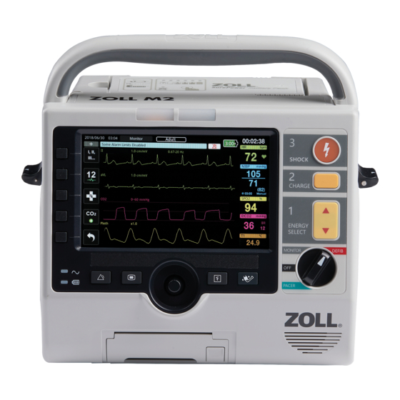
Page 35: The Front Panel
Controls and Indicators The Front Panel The front panel of the ZOLL M2 device includes a display screen and various buttons, keys, and indicators that provide feedback to the user. See Figure 2-1. Refer to Table 2 on page 2-3 for information about the controls and indicators. - Page 36 Chapter 2 Product Overview Table 2: ZOLL M2 Controls and Indicators (Continued) Control or Indicator Description Mode Selector Selects the mode of operation: • OFF — Unit is powered off • MONITOR — Physiological monitoring • DEFIB — Manual defibrillation or AED •...
-
Page 37: Display Screen
The unit displays the information in user-configurable colors. Battery Patient WiFi Operation Date and time type status status status Time elapsed mode Status/ Alarm message Heart rate Quick access keys Waveform display Figure 2-2 ZOLL M2 Display Screen 9650-000860-01 Rev. C ZOLL M2 Operator’s Guide... -
Page 38: Battery Status And Ac Power Indicators
1:30+ and 2:30+. Note: Upon powering up the ZOLL M2 unit, the battery capacity will be displayed within a short period under normal conditions. Under some circumstances, such as activating the monitor/defibrillator immediately after the unit is turned on, the battery icon may display less than one hour battery capacity for up to two minutes after exiting the defibrillation mode. -
Page 39: Patient Cables And Connectors
Controls and Indicators Patient Cables and Connectors The back of the ZOLL M2 unit includes connectors for patient cables. Figure 2-3 Patient Cable Connectors on back of the ZOLL M2 Unit Connector Description For connecting 3-lead or 5-lead ECG cable. - Page 40 Chapter 2 Product Overview Cables and Accessories The ZOLL M2 unit ships with an MFC with CPRD connector. This cable can be used with hands-free electrodes for ECG monitoring, defibrillation, external pacing, and CPR monitoring/ feedback; this cable cannot be used with internal or external paddles.
- Page 41 Figure 2-4 MFC Connected to Unit Inserting Test Connector into MFC (30J Self Test) To perform a 30J self-test, plug in the test connector as shown. Figure 2-5 30J Self Test with MFC 9650-000860-01 Rev. C ZOLL M2 Operator’s Guide...
-
Page 42: External Paddles
Figure 2-6 30J Self Test with CPRD Connector External Paddles External paddles are defibrillation-proof Type CF equipment. The external paddles on the ZOLL M2 device are used for defibrillation and synchronized cardioversion. Caution You cannot use paddles for external transcutaneous pacing. - Page 43 Figure 2-7 Paddle Release Attaching the MFC Cable Attach the MFC from the ZOLL M2 unit to the connector at the base of the APEX paddle. Insert into connector Figure 2-8 MFC Connected to APEX Paddle If you need to detach the MFC from the APEX paddles, push the RELEASE button in the direction of the arrow and unplug the MFC.
- Page 44 Slide the Adult plate onto the paddle until it locks into place. Figure 2-9 Pediatric Plate Note: The ZOLL M2 monitor/defibrillator also supports ZOLL autoclavable internal paddles for use during open chest defibrillation procedures. 2-12 www.zoll.com 9650-000860-01 Rev. C...
-
Page 45: Navigating The Display Screen
Navigating the Display Screen You can access the ZOLL M2 functions using the quick access keys that are located on the left side of the display screen, and the Trim Knob that is located in the middle of the front panel. - Page 46 Chapter 2 Product Overview Table 3: ZOLL M2 Quick Access Keys Quick access key Description Code Marker Allows you to note clinical treatments in the patient record. Sync Activates the synchronized cardioversion mode. More/Back Goes to the next or previous level of quick access keys.
-
Page 47: Trim Knob
Navigating the Display Screen Table 3: ZOLL M2 Quick Access Keys Quick access key Description Disarm Safely discharges the defibrillator internally. No energy is delivered to the patient. 30 Joule Test Performs 30 joule defibrillator test. Enable/Disable 4:1 pacer mode. -
Page 48: Using Code Markers
Replacing a Battery Pack on the ZOLL M2 Unit This section describes how to replace a battery pack on the ZOLL M2. Replacing a Battery Pack on the ZOLL M2 To remove a battery pack, press the tab on the end of the battery pack inward, then lift the battery pack out of the compartment. -
Page 49: Chapter 3 Monitoring Overview
The ZOLL M2 unit provides standard monitoring functions, and allows you to view the vital signs measurements in a variety of formats. The ZOLL M2 unit also allows you to set alarm limits for the monitoring functions. If a patient’s vital signs measurements go outside of these limits when alarm functions are enabled, the ZOLL M2 issues an audible alarm tone and displays visual alarm indications to alert you. -
Page 50: Ecg
ECG source (such as PADS, ECG Leads I, II, III, aVR, aVL, aVF, or V). You can configure the ZOLL M2 unit to display up to four ECG waveform traces. In addition to being able to specify the ECG source for each waveform trace, you can adjust the display scale of those traces to make them easier to view. -
Page 51: Inserting, Removing, Or Replacing A Waveform Trace
Rotate the Trim Knob to the X in the top right corner of the window and press the knob • to leave the window. Press the Menu button to leave the window. • 9650-000860-01 Rev. C ZOLL M2 Operator’s Guide... - Page 52 Chapter 3 Monitoring Overview In the example below, a ECG Lead II trace is inserted below the current trace (Lead I). Insert Lead II Lead II appears here www.zoll.com 9650-000860-01 Rev. C...
-
Page 53: Chapter 4 Trends
Chapter 4 Trends The ZOLL M2 unit logs a patient’s vital signs trend information to memory at user configurable intervals between 30 seconds and 30 minutes (default is 30 seconds). It also logs all monitored vital sign measurements when a patient alarm occurs. -
Page 54: Viewing The Patient Trend Data Window
See the following procedure to view incidents in the Patient Trend Data window. Note: Turning off the ZOLL M2 unit for more than 30 seconds ends an incident. When the unit is turned back on after more than 30 seconds without power, the unit creates a new incident even if the same patient is being monitored. -
Page 55: Printing Trend Information
Knob to select it. See the following step for an example of a Trend Data Report. Press the X in the top right hand corner to exit the Trend window, or press Back to go back to the Patient Trend Data window. Figure 4-2 Trend Data Report 9650-000860-01 Rev. C ZOLL M2 Operator’s Guide... - Page 56 Chapter 4 Trends www.zoll.com 9650-000860-01 Rev. C...
-
Page 57: Chapter 5 Alarms
An equipment alarm is issued when an equipment-related condition that adversely affects or limits the ZOLL M2’s operation is detected, such as a disconnected ECG lead or defibrillator electrode, malfunctioning pulse oximetry sensor, or internal diagnostics failure. An equipment alarm condition is also indicated in three ways: beeping alarm tone, text message, and flashing indicator lights on the front panel of the unit. -
Page 58: Alarm Indicator Self-Test
Chapter 5 Alarms Alarm Indicator Self-Test The ZOLL M2 unit performs a self-test of the audible and visual alarm indicators upon start up. To ensure that the alarms are functioning properly, verify that you hear an alarm tone and the indicator lights are illuminated for three seconds upon start up of the unit. -
Page 59: Equipment Alert Display
Figure 5-2 Multiple Alarms Display Equipment Alert Display When a problem with the ZOLL M2 unit or an attached sensor triggers an alarm, in addition to an alarm tone and the flashing indicator lights of an equipment alarm, the ZOLL M2 unit... -
Page 60: Visual And Audible Alarm Indicators
Figure 5-3 Equipment Alarm Display Visual and Audible Alarm Indicators In addition to status/alarm messages that appear on the display, the ZOLL M2 unit illuminates the red or yellow indicator lights on the front panel and emits an audible alarm to show the priority level of the highest-priority active alarm. -
Page 61: Responding To Active Patient Alarms
) for one to three seconds. The Alarm Audio Off icon ( ) and the ALARM AUDIO OFF message display to indicate the status. No audio alarms are issued as long as the ZOLL M2 unit is in this mode. Note: The visual alarm indicators still flash and alarming parameters are highlighted while the patient alarm audio is off. -
Page 62: Disabling Patient Alarms
When audible alarms are disabled, make sure that the patient is closely observed. Alarm Reminders The ZOLL M2 unit may be configured to sound a reminder alarm at specified intervals. When the Alarm Off Prompting feature is enabled, a single beep sounds for the duration of 190 ms every 5, 10, or 15 minutes (depending on configuration) if an Audio Off or Alarm Off condition persists. -
Page 63: Responding To Equipment Alarms
Attempt to correct the equipment alarm condition if possible. For example, for the ECG LEAD OFF alarm, check the ECG lead connection to the patient or the connection to the ZOLL M2 unit. Also, refer to “ECG System Messages” on page 6-13 or “Troubleshooting” on page 13-11”. - Page 64 • Do not set alarm limits to extreme values that render the alarm system useless. • A potential hazard can exist if different alarm presets are used for the patient monitoring equipment in a single area. www.zoll.com 9650-000860-01 Rev. C...
-
Page 65: Chapter 6 Monitoring Ecg
Chapter 6 Monitoring ECG This chapter describes how to use the ZOLL M2 device to monitor ECG. ZOLL M2 units can perform ECG monitoring through 3-lead or 5-lead ECG patient cables, multi-function pads, or defibrillation paddles. 9650-000860-01 Rev. C ZOLL M2 Operator’s Guide... - Page 66 • Check the operation and integrity of the ZOLL M2 unit and ECG cable regularly by performing the Daily Operational Verification Test. • Implanted pacemakers may cause the heart rate meter to count the pacemaker rate during incidents of cardiac arrest or other arrhythmias.
-
Page 67: Ecg Monitoring Setup
Apply the electrodes to the patient. Connect each lead of the ECG cable to the appropriate electrode. Plug the patient cable into the ECG input connector on the ZOLL M2 unit. Select the ECG waveforms to be displayed on the waveform trace display screen. -
Page 68: Applying Electrodes To The Patient
LA/Black Electrode L/Yellow Electrode Place near patient’s left mid-clavicular line, directly below clavicle. LL/Red Electrode F/Green Electrode Place between 6th and 7th intercostal space on patient’s left mid-clavicular line. Figure 6-1 3-Lead Electrode Placement www.zoll.com 9650-000860-01 Rev. C... - Page 69 V4 (C4) -- 5th intercostal space at mid- clavicular line. V5 (C5) -- Same transverse level as V4 at left anterior-axillary line. V6 (C6) -- Same transverse level as V4 at left mid-axillary line. Figure 6-2 5-Lead Electrode Placement 9650-000860-01 Rev. C ZOLL M2 Operator’s Guide...
-
Page 70: Connecting The Ecg Cable To The Zoll M2 Unit
Chapter 6 Monitoring ECG Connecting the ECG Cable To the ZOLL M2 Unit Connect the ECG cable to the ECG connector on the back of the ZOLL M2 unit as follows: Align arrows on cable and connector Arrow lines up with... -
Page 71: Selecting Ecg Waveforms For Display
ECG Monitoring Setup Selecting ECG Waveforms for Display In Monitor mode, the ZOLL M2 device can fit up to four waveforms on the display. The first waveform at the top of the display is always an ECG waveform. In the following example,... -
Page 72: Selecting The Waveform Trace Size
Paddles ECG signal (solid line) even when paddles are shorted together or not connected to the patient. For more information on how to configure the display of waveforms on the ZOLL M2 device, see Chapter 3, Monitoring Overview. -
Page 73: Diagnostic Ecg
When the Pace Marker setting is off, the Pacer Off Marker icon ( ) appears at the top of the display screen. In this setting, implanted pacer pulses are not detected by the ZOLL M2 unit or eliminated from the ECG signal. -
Page 74: Accessing The Ecg Setting Window
When you are finished viewing and making changes to the settings, do one of the following: Rotate the Trim Knob to the X in the top right corner of the window and press the knob • to leave the window. Press the Menu button to leave the window. • 6-10 www.zoll.com 9650-000860-01 Rev. C... -
Page 75: Heart Rate Meter
Meter Configuring Heart Rate (HR) Meter Alarms The ZOLL M2 unit allows you to enable and disable the Heart Rate (HR) alarm, to set alarm limits, and to select a QRS detection tone volume. The default HR alarm settings (enable/ disable, alarm limits) are supervisor configurable. -
Page 76: Enabling/Disabling Hr Alarms And Setting Alarm Limits
Chapter 6 Monitoring ECG Enabling/Disabling HR Alarms and Setting Alarm Limits When enabled, the ZOLL M2 unit sounds and displays alarms whenever the patient’s heart rate is above or below the specified heart rate alarm limits. You can enable (or disable) HR alarms and set Upper and Lower alarm limits using the Alarm... -
Page 77: Ecg System Messages
ECG System Messages ECG System Messages When monitoring ECG, the ZOLL M2 unit may display the following messages: Message Cause/Action APPLY PADDLES TO PATIENT Paddles are in an open condition. Apply paddles firmly to the patient’s chest. Therapy pads are not connected to the patient. Check ATTACH PADS the MFC/pads/paddles connections. - Page 78 Chapter 6 Monitoring ECG 6-14 www.zoll.com 9650-000860-01 Rev. C...
- Page 79 (LEDs) that transmit red and infrared light through the body’s extremities. The transmitted light is then received by a photodetector within the sensor, which converts it to an electronic signal. The signal is then sent to the ZOLL M2 unit for processing.
-
Page 80: Monitoring Spo2
Directions for Use contained with all sensor packages. Note: The ZOLL M2 displays the pulse rate (PR) value when you do not connect ECG leads or defibrillation electrodes to the patient. Note: The SpO sensor’s LED wavelength information (Appendix A) can be especially... -
Page 81: Cautions
When an event such as a component drop of a 1/2 meter or greater or a spillage of blood or other liquids on/into the unit occurs, retest before further use to avoid personal injury. 9650-000860-01 Rev. C ZOLL M2 Operator’s Guide... -
Page 82: Spo2 Setup And Use
NIBP cuff. Inflation of the cuff will cause the SpO values to read incorrectly. Check that the patient type displayed on the ZOLL M2 unit is appropriate for the patient. www.zoll.com 9650-000860-01 Rev. C... -
Page 83: Connecting The Spo2 Sensor
ZOLL M2 rear panel connector, then push the cable connector into the panel connector. Displaying SpO Measurements When the connection is made between the sensor and the ZOLL M2 unit, the unit displays the plethysmograph normalized waveform and the messages PULSE SEARCHING and INITIALIZING. The SpO numeric display window is shown on the right side of the unit. -
Page 84: Adjustable Spo2 Settings
Setting the Sensitivity Level The ZOLL M2 unit allows you to select Low, Medium, or High sensitivity for SpO monitoring. Medium sensitivity is recommended for most patients. Under very low perfusion conditions, such as severe hypotension or shock, high sensitivity might provide more accurate measurements. -
Page 85: Adjusting The Plethysmogram Display
The amplitude of the normalized plethysmogram remains constant for all patients. The shape of the waveform itself is variable. Adjusting the Size of the Plethysmogram The ZOLL M2 unit allows you to adjust the size of displayed the SpO plethysmogram waveform. To select the waveform size: 1. - Page 86 Chapter 7 Monitoring SpO2 Enabling/Disabling SpO Alarms and Setting Alarm Limits When enabled, the ZOLL M2 unit sounds alarms whenever measurements are outside set limits for the high and low SpO values (and, if monitoring is on, PR value). You can enable (or disable) alarms and set Upper and Lower alarm limits through the Alarm...
-
Page 87: Spo2 System Messages
SpO2 System Messages System Messages When monitoring SpO , the ZOLL M2 unit may display the following system messages: System Message Cause/Action The pulse oximeter function is starting up and preparing INITIALIZING to begin searching for arterial pulses. Arterial pulsations are too weak to allow accurate SpO LOW PERFUSION measurements. - Page 88 Chapter 7 Monitoring SpO2 7-10 www.zoll.com 9650-000860-01 Rev. C...
-
Page 89: Chapter 8 Automated External Defibrillator (Aed) Operation
Manual Mode Operation” on page 8-12). Modes of Operation The ZOLL M2 monitor/defibrillator can be configured to operate as either an AED or a manual defibrillator when the Mode Selector is initially set to the DEFIB position. The operating mode 1. -
Page 90: Patient Type
Patient Type The ZOLL M2 AED can operate in either the Adult or Pediatric mode based on the adult or pediatric patient type selection. In adult mode, the ECG analysis algorithm and automatic defibrillator energy selections are tailored for use on adult patients. In pediatric mode, the ECG analysis algorithm and defibrillator energy selections are oriented toward use on pediatric patients from 1 - 8 years of age or <... -
Page 91: Determine Patient Condition Following Medical Protocols
Once you have set the patient type, the ZOLL M2 selects and displays the default energy for that patient type. After the first shock is delivered, the ZOLL M2 automatically escalates the shock energy setting for the next shock that is appropriate for the patient. -
Page 92: Turn On Unit
ALL TESTS PASSED. If no hands-free therapy electrodes have been attached to the patient and connected to the ZOLL M2 unit, the ATTACH PADS message and voice prompt will be issued. www.zoll.com 9650-000860-01 Rev.C... -
Page 93: Set Patient Type
Signifies the unit is in AED Mode Follow the prompts to begin the rescue. If the ZOLL M2 unit has been configured to begin CPR upon start up, it will automatically begin with the CPR interval (the default setting starts with analysis). - Page 94 PADS or CHECK PADS message is displayed and analysis will be inhibited. Note: If the ZOLL M2 unit has been configured to perform CPR at startup, it displays a configurable CPR message along with a voice prompt for the configured duration before analysis begins.
- Page 95 See “3 Press SHOCK” on page 8-8 for the next steps to follow. No Shock Advised When a nonshockable rhythm is detected, the unit displays a NO SHOCK ADVISED message. After this message, immediately begin chest compressions and continue other treatments per protocol. 9650-000860-01 Rev.C ZOLL M2 Operator’s Guide...
-
Page 96: Press Shock
Note: If ZOLL CPR pads are connected and the patient is an adult, the unit monitors the rate and depth of chest compressions and can display PUSH HARDER and GOOD COMPRESSIONS messages and voice prompts. -
Page 97: Cpr Dashboard
CPR Rate The CPR rate value displays the current chest compression rate (compressions per minute) determined by the ZOLL M2 unit. When no chest compressions have been detected during the past few seconds, the rate display shows "---". CPR Compression Detection Indicator This indicator provides a compression signal that flashes with each detected compression to inform the user that his/her compressions are being detected. -
Page 98: Operating Messages
Supervisor Menu. Operating Messages The ZOLL M2 device uses both audio and visual prompts to present critical information to operators. The device only issues audio prompts once, but continues to display visual prompts until you take a new action or the device status changes. The following information describes the unit default configuration. - Page 99 This message is displayed and announced when the unit detects a shockable rhythm after a full Analysis/CPR cycle when the ZOLL M2 is configured to pause after each CPR period. In this configuration, the ANALYZE button initiates the ECG analysis/CPR cycle.
-
Page 100: Switching To Manual Mode Operation
If you enter the wrong password, the unit remains in AED mode. To transfer back to AED mode from Manual Defib mode, power off the unit for more than 30 seconds and then power it back on. 8-12 www.zoll.com 9650-000860-01 Rev.C... -
Page 101: Chapter 9 Manual Defibrillation
The Manual Defibrillation mode (or Manual mode) provides the user with full control over the defibrillator's functions. This mode allows for determining the need for treatment, selecting the defibrillator energy setting, charging the unit, then delivering therapy when needed. 9650-000860-01 Rev.C ZOLL M2 Operator’s Guide... -
Page 102: Modes Of Operation
(when using ZOLL CPR sensor-equipped electrodes). Patient Type The ZOLL M2 can operate in either the Adult or Pediatric mode; select adult for adult patients, select pediatric for pediatric/neonate patients. In adult mode, the automatic defibrillator energy selections are tailored for use on adult patients. In the pediatric mode, the defibrillator energy selections are oriented towards use on patients from 1 - 8 years of age or <... -
Page 103: Turn On Unit
ALL TESTS PASSED displays. Note: If the ZOLL M2 unit is configured to start up in AED mode, you need to press the Manual Defib quick access key on the left side of the display to enter the Manual mode of operation. - Page 104 Ensure that the paddles are connected to the multi-function cable (MFC), and that the cable is connected to the ZOLL M2 unit. Apply a liberal amount of electrolyte gel to the electrode surface of each paddle, and rub the electrode surfaces together to evenly distribute the applied gel.
-
Page 105: Charge Defibrillator
Press the CHARGE button on the APEX paddle handle or on the front panel. SHOCK CHARGE ENERGY SELECT If the SHOCK buttons on the paddles are depressed when the unit is charging, a RELEASE SHOCK BUTTON message appears on the display. 9650-000860-01 Rev.C ZOLL M2 Operator’s Guide... - Page 106 When the unit is fully charged, the tone changes to a continuous charge ready tone, and the READY message displays at the bottom of the screen. The charge indicator on the apex paddle illuminates with the ZOLL M2 unit is ready to deliver defibrillation energy to the patient.
-
Page 107: Deliver Shock
The delivered energy level and the shock number (1) are displayed at the bottom of the screen. If additional countershocks are needed, follow steps 1 through 3 of this procedure starting on page 9-3 to readjust the energy settings, charge the unit, and deliver the shock. 9650-000860-01 Rev.C ZOLL M2 Operator’s Guide... -
Page 108: Emergency Defibrillation Procedure With Hands-Free Therapy Electrodes
Chapter 9 Manual Defibrillation Emergency Defibrillation Procedure with Hands-Free Therapy Electrodes ECG leads and ZOLL hands-free therapy electrodes are a defibrillation-protected Type CF patient connection (applied part). Determine the Patient’s Condition Following Local Medical Protocols Verify: Unconsciousness • Absence of breathing •... -
Page 109: Turn On Unit
ALL TESTS PASSED displays. Note: If the ZOLL M2 unit is configured to start up in AED mode, you need to press the Manual Defib quick access key on the left side of the unit to enter the Manual mode of operation. -
Page 110: Select Energy Level
If Shocks 1, 2, and 3 have been configured to escalating energy levels using the Auto Energy Escalation feature, the ZOLL M2 unit automatically sets the energy to the preconfigured Energy Level: Shock 1, 2, 3 setting at power-up and after each of the first two shocks. -
Page 111: Charge Defibrillator
Press the CHARGE button again to charge the unit to the newly selected energy level. A CHARGING message displays at the bottom of the screen, and a distinctive tone sounds indicating that the unit is charging. 9650-000860-01 Rev.C ZOLL M2 Operator’s Guide 9-11... -
Page 112: Deliver Shock
Press and hold the SHOCK button on the front panel until energy is delivered to the patient. SHOCK CHARGE ENERGY SELECT 9-12 www.zoll.com 9650-000860-01 Rev.C... - Page 113 If additional countershocks are needed, follow steps 1 through 3 of this procedure starting on page 9-10 to readjust the energy settings, charge the unit, and deliver shock. 9650-000860-01 Rev.C ZOLL M2 Operator’s Guide 9-13...
-
Page 114: Synchronized Cardioversion
T-wave segment of the cardiac cycle. The ECG signal used for synchronized cardioversion can be derived from hands-free electrodes, defibrillator paddles or ECG limb/chest leads. ZOLL recommends that hands-free electrodes or ECG leads be favored over paddles ECG which is susceptible to artifact caused by paddle movement. -
Page 115: Synchronized Cardioversion Of Atrial Fibrillation
Synchronized Cardioversion of Atrial Fibrillation Cardioversion of atrial fibrillation (AF) and overall clinical effectiveness is enhanced by proper pad placement. Clinical studies (refer to above) of the ZOLL M2 Biphasic Defibrillator Waveform demonstrated that high conversion rates are achieved when defibrillation pads are placed as shown in the following diagram. -
Page 116: Turn On Unit
ALL TESTS PASSED displays. Note: If the ZOLL M2 unit is configured to start up in AED mode, you need to press the Manual Defib quick access key on the left side of the unit to enter the Manual mode of operation. -
Page 117: Select Energy Level
Press the CHARGE button on the front panel or on the APEX paddle handle. SHOCK CHARGE ENERGY SELECT To increase or decrease the selected energy after you have pressed the CHARGE button, use the defibrillator ENERGY SELECT arrows on the front panel or sternum panel. 9650-000860-01 Rev.C ZOLL M2 Operator’s Guide 9-17... -
Page 118: Deliver Shock
When an internal handle set is connected to the ZOLL M2 unit, it automatically sets the selected energy to 10 Joules. The maximum allowed energy selection is 50 Joules when internal paddles are in use. -
Page 119: Verification Prior To Use
Internal Handle and Electrode Operator’s Guide. Verification Prior to Use Before each use with the ZOLL M2 unit, verify the proper operation of the ZOLL internal paddles using the following procedure. This procedure requires a second person if internal handles being used are without a Discharge button. - Page 120 Chapter 9 Manual Defibrillation 9-20 www.zoll.com 9650-000860-01 Rev.C...
-
Page 121: Chapter 10 Real Cpr Help
When applied according to package instructions, CPR electrodes provide a chest compression sensor that is located between the rescuer's hands and the patient's lower sternum. This sensor monitors the rate and depth of chest compressions and sends this information to the ZOLL M2 unit for processing and display. -
Page 122: Cpr User Interface
CPR periods and is replaced with defibrillation messages during non-CPR periods. When the ZOLL M2 is in the Manual Defib mode, the CPR Dashboard replaces the lowest waveform trace (displayed at the bottom of the screen) when the following conditions are met: CPR electrodes are connected •... -
Page 123: Cpr Rate Metronome
In AED mode, the metronome beeps are issued at the configured rate when CPR electrodes are in use and the ZOLL M2 unit is in a CPR period. The metronome can also be configured to begin beeping after the first few chest compressions are detected and continue to beep until chest compressions have stopped for more than a few seconds. -
Page 124: Cpr Compression Bar Graph
Chapter 10 Real CPR Help CPR Compression Bar Graph When the ZOLL M2 monitor/defibrillator has CPR electrodes connected to it and detects repeating chest compressions over a short period of time, it displays the compression depth bar graph at a sweep speed of 12.5 mm/sec. The CPR compression bar graph is computed from the CPR sensor signals and displays above the dashboard. -
Page 125: External Pacing
Chapter 11 External Pacing ECG leads and ZOLL hands-free therapy electrodes are a defibrillation-protected Type CF patient connection (applied part). WARNING! To avoid risk of electrical shock, do not touch the gelled area of the hands-free therapy electrodes while pacing. -
Page 126: Pacer Modes
Clear quick access key to respond to the alarm. Pacer Modes The ZOLL M2 has two pacer mode settings: Demand and Fixed. The defibrillator always defaults to the Demand pacer setting when the Pacer function is initially activated. -
Page 127: Apply Ecg Electrodes
Verify that R-waves are being properly detected by confirming that a QRS tone (and/or flashing heart beat light) occurs with each displayed R-wave or by verifying that the ZOLL M2 unit’s heart rate display accurately reflects the patient’s pulse rate. -
Page 128: Turn Mode Selector To Pacer
If no intrinsic rate exists, use 100 ppm. You can increase or decrease the pacer rate in increments of 2 ppm. Note: The default pacing rate is 70 ppm. This default rate is configurable. 11-4 www.zoll.com 9650-000860-01 Rev. C... -
Page 129: Start Pacer
Note: If pacing was active during the past 10 minutes and the ZOLL M2 has not been turned off for more than 30 seconds since the pacing episode, the unit begins pacing at the last current setting about 3 seconds after activation of the pacer mode. The Pacer current defaults to the 0 mA setting under all other conditions. -
Page 130: Determine Optimum Threshold
Fixed pacing should be performed only in an emergency when no alternative is available. Note: When ECG leads are off during pacing, the ZOLL M2 unit always reverts to fixed rate pacing. Determine Patient Condition and Provide Care Following Local... -
Page 131: Apply Hands-Free Therapy Electrodes
Turn the Mode Selector to PACER. If the unit was previously turned off, the red and yellow lights on the top of the unit flash on and off, and then the unit displays the message ALL TESTS PASSED. The Pacer Dashboard displays: 9650-000860-01 Rev. C ZOLL M2 Operator’s Guide 11-7... -
Page 132: Set Pacer Mode
Note: If pacing was active during the past 10 minutes and the ZOLL M2 unit has not been turned off for more than 30 seconds since the pacing episode, the unit begins pacing at the last current setting about 3 seconds after activation of the pacer mode. -
Page 133: Determine Capture
Determination of electrical capture should only be performed by viewing the ECG trace on the ZOLL M2 display with its ECG connection directly attached to the patient. Use of other ECG monitoring devices might provide misleading information due to the presence of pacer artifacts. -
Page 134: Pediatric Pacing
33 lbs/15 kg. If it is necessary to pace for more than 30 minutes, periodic inspection of the underlying skin is strongly advised. Carefully follow all instructions on electrode packaging. Pacing Messages The ZOLL M2 unit may display the following messages when pacing. System Message Description... -
Page 135: Chapter 12 Incident Data And Reports
Recording” on page 12-13. Note: The ZOLL M2 unit retains stored incidents even if you turn off the unit, remove its battery power, and disconnect it from AC mains until its memory is full. When memory is full, new incident data automatically replaces the oldest data in memory. -
Page 136: Data Storage
CASE FILE FULL message. When a CASE FILE FULL message appears, additional patient data can be stored in a new case file by powering the ZOLL M2 unit off for 30 seconds, and then powering it back on. The ZOLL M2 unit stores completed cases until its memory is full, and then erases old cases (one by one) to make room for the current incident. -
Page 137: Printing Summary Report
Rotate the Trim Knob to highlight the incident you want to print and then press the knob to select it. A green check mark displays next to the selected incident. Note: You can only select one incident at a time to print. 9650-000860-01 Rev. C ZOLL M2 Operator’s Guide 12-3... -
Page 138: Event Log
Chapter 12 Incident Data and Reports Rotate the Trim Knob to highlight Print Incident and press the knob to select it. The ZOLL M2 unit prints the summary report for the incident you have selected. When the Summary Report has finished printing, do one of the following: Rotate the Trim Knob to the X in the top right corner of the window and press the knob •... - Page 139 A green check mark displays next to the selected incident. Rotate the Trim Knob to highlight Print Event Log and press the knob to select it. The ZOLL M2 unit prints the event log for the incident you have selected.
-
Page 140: Snapshots
Figure 12-2. Event Log Snapshots When one of the events described in “Event Log” on page 12-4 occurs, the ZOLL M2 automatically captures and saves up to 6 seconds of physiological waveform and other data that preceded the event and 12 seconds of data following the event. This data capture is called a snapshot. -
Page 141: Snapshot Types
Snapshots Snapshot Types The ZOLL M2 unit triggers snapshots in response to nine different types of events. Besides the information in the previous section that is included with every snapshot, the ZOLL M2 unit stores additional information in each of the following types of snapshots. - Page 142 Defib and/or Monitor mode when heart rate alarms are enabled and the ZOLL M2 unit detects ventricular fibrillation or wide complex ventricular tachycardia in the patient’s ECG rhythm. Additional information in this snapshot includes the device operating mode (AED, DEFIB, MONITOR), and CHECK PATIENT annotation with the left edge of the annotation directly above the ECG signals recorded when the alarm occurred.
- Page 143 (high or low). Figure 12-8. Patient Alarm Snapshot 9650-000860-01 Rev. C ZOLL M2 Operator’s Guide 12-9...
- Page 144 This snapshot is taken when a code marker is entered. No ECG is printed in this case, just the code marker snapshot header and a record of the selected code marker. Figure 12-10. Code Marker Snapshot 12-10 www.zoll.com 9650-000860-01 Rev. C...
- Page 145 Snapshots Diagnostic ECG This snapshot is taken when the ZOLL M2 unit is in Monitor mode and the Diag ECG front panel quick access key is pressed. ECG data captured in this snapshot is filtered with a .525-40 Hz frequency response in order to accurately preserve ST segment elevation or depression characteristics.
-
Page 146: Printing Snapshots
Chapter 12 Incident Data and Reports Printing Snapshots The ZOLL M2 unit can be configured to automatically print some or all types of snapshots as they are acquired, or to store each snapshot without printing. This configuration is in the Supervisor menus. -
Page 147: Full Disclosure Recording
A green check mark displays next to the snapshot(s) that you have selected to print. Rotate the Trim knob to highlight Print, and press the knob to select it. The ZOLL M2 unit prints the snapshot(s) you have selected. - Page 148 Warning! To avoid a possible shock hazard, do not make any electrical connections to the USB port except to connect a USB flash drive while the ZOLL M2 unit is connected to or within touching distance of the patient. 12-14 www.zoll.com...
-
Page 149: Transferring Full Disclosure Recording Using Wifi
Full Disclosure Recording Transferring Full Disclosure Recording Using WiFi For units with an SFTP server configured, the ZOLL M2 unit allows you to send patient disclosure logs to a remote server through a wireless connection. WiFi and SFTP settings can be configured in the Supervisor System Main menu. -
Page 150: Deleting A Rescue Incident
Do one of the following: Rotate the Trim Knob to the X in the top right corner of the window and press the knob • to leave the window. Press the Menu button to leave the window. • 12-16 www.zoll.com 9650-000860-01 Rev. C... -
Page 151: Setting Up A Wireless Configuration/Sftp Server
Setting Up a Wireless Configuration/SFTP Server This section describes how to set up a wireless connection and SFTP server for your ZOLL M2 unit in order to send full disclosure files through a wireless connection. The files are sent over WiFi using a Secure File Transfer Protocol (SFTP) which requires that a SFTP server be used at the receiving end. - Page 152 Subnet Mask (format is 255.255.255.0). Preferred DNS Use the numeric keypad to enter your Preferred DNS IP address (format is 0.0.0.0). Alternate DNS Use the numeric keypad to enter your Alternate DNS IP address (format is 0.0.0.0) 12-18 www.zoll.com 9650-000860-01 Rev. C...
-
Page 153: To Set Up An Sftp Server
Alternate DNS IP address (format is 0.0.0.0) Server Port The server port cannot be changed. Username Use the alpha-numeric keypad to enter the SFTP server username. Password Use the alpha-numeric keypad to enter the SFTP server password. 9650-000860-01 Rev. C ZOLL M2 Operator’s Guide 12-19... - Page 154 Repeat steps 2 and 3 until you have selected all the numbers/letters for the field. Rotate the knob to highlight the Enter key and press the knob to select it. The selected characters display in the field in the applicable window. 12-20 www.zoll.com 9650-000860-01 Rev. C...
-
Page 155: Chapter 13 Maintenance And Troubleshooting
, ZOLL suggests using an operator’s shift check list, which is included in this chapter (and can be copied for use as needed). Warning! Do not perform service on the ZOLL M2 unit while it is connected to a patient. 1. JAMA. 1990;264:1019-1025 9650-000860-01 Rev. C ZOLL M2 Operator’s Guide... -
Page 156: Daily/Shift Check Procedure
Daily/Shift Check Procedure Inspection Equipment and Accessories Ensure that the ZOLL M2 unit is clean (with no fluid spills) and free of visible damage. • Inspect all cables, cords, and connectors for signs of damage or excessive wear (cuts in •... -
Page 157: Defibrillator/Pacing Test
Connect the external AC cable to a working Verify that the green AC mains power LED AC outlet and to the ZOLL M2 rear panel. illuminates on the ZOLL M2 front panel. Insert a battery into the unit (if a battery is not Verify that the Battery charge LED on the already installed). - Page 158 Diag quick access key. 15 Reconnect the external AC power to the Verify that the green AC mains power LED on ZOLL M2 rear panel. the ZOLL M2 front panel is illuminated. 13-4 www.zoll.com 9650-000860-01 Rev. C...
-
Page 159: Defibrillator Testing With External Paddles
Defibrillator Testing with External Paddles Defibrillator Testing with External Paddles Prior to testing external defibrillator paddles with the ZOLL M2 unit, complete the testing described in “Defibrillator/Pacing Test” on page 13-3. Note: If a LOW BATTERY or REPLACE BATTERY message appears during any of this testing, the battery is close to depletion and should be recharged or replaced. -
Page 160: Spo2 Functional Check
Function Response Plug the sensor cable into the SpO receptacle on the back of the ZOLL M2 unit. Turn the Mode Selector to MONITOR to turn on the unit. Place the SpO sensor onto an appropriately sized finger, and ensure that the sensor’s... -
Page 161: Recommended Minimum Preventive Maintenance Schedule
Caution DO NOT leave ZOLL M2 battery packs in a completely discharged state. Damage to the battery packs can occur if they are left in a completely discharged state for more than 14 days. 9650-000860-01 Rev. C ZOLL M2 Operator’s Guide... -
Page 162: Cleaning Instructions
Cleaning the ZOLL M2 unit To clean the ZOLL M2 unit, use a nearly dry cloth containing one of the cleaning agents listed below. DO NOT allow cleaning agent or water to run into the crevices or connector openings at any time. -
Page 163: Cleaning The Print Head
Refer to the illustration inside of the paper compartment for proper paper orientation, and place a new pad of stripchart paper in the tray. Note: Paper feeds from the top of the stack with gridlines facing up. 9650-000860-01 Rev. C ZOLL M2 Operator’s Guide 13-9... - Page 164 Close the printer door. Be sure that the printer door is flush with the bottom front face of the unit. Figure 13-2. Inserting the Paper and Closing Printer Door After the paper is loaded, press the Print quick access key to resume printing. 13-10 www.zoll.com 9650-000860-01 Rev. C...
-
Page 165: Troubleshooting
The unit is unable to establish communication with the battery. Check the battery contacts. Buttons do not respond, e.g., Turn the ZOLL M2 unit off and then turn it back on to quick access keys do not correct the fault. If the fault still exists, contact the function. - Page 166 Chapter 13 Maintenance and Troubleshooting Symptom Recommended Action The device cannot switch Turn the ZOLL M2 unit off and then turn it back on to modes (non-AED use). correct the fault. If the fault still exists, contact the appropriate technical personnel or ZOLL Technical Service Department.
- Page 167 • Verify that the cable is properly connected to the displayed on the screen. unit and to the patient. • Turn the ZOLL M2 unit off and then turn it back on to correct the fault. If the fault still exists, contact the appropriate technical personnel or ZOLL Technical Service Department.
- Page 168 One of the following conditions has occurred: • The printer head is overheating. • The printer motor is overheating. • Printer communication is interrupted. If print head/motor has overheated, it will restart when it has cooled down. 13-14 www.zoll.com 9650-000860-01 Rev. C...
- Page 169 Troubleshooting ZOLL M2 OPERATOR’S SHIFT CHECKLIST Date: ________________ Shift: _______________ Location: _______________ Mfr/Model No.: ____________________________ Serial No. or Facility ID No.: _________________ At the beginning of each shift, inspect the unit. Indicate whether all requirements have been met. Note any corrective actions taken. Sign the form.
- Page 170 Chapter 13 Maintenance and Troubleshooting 13-16 www.zoll.com 9650-000860-01 Rev. C...
- Page 171 Appendix A Specifications This chapter provides specification information for the ZOLL M2 monitor/defibrillator. “Defibrillator” on page A-2 • “Display” on page A-2 • “ECG” on page A-2 • “Alarms” on page A-5 • “Recorder” on page A-6 • “Battery” on page A-7 •...
-
Page 172: Defibrillator
Specifications Defibrillator Waveform: ZOLL Rectilinear Biphasic™ waveform Energy Selections: 1,2, 3, 4, 5, 6, 7, 8, 9, 10, 15, 20, 30, 50, 70, 85, 100, 120, 150, 200 joules. Charge Time: Less than 7 seconds at rated mains voltage and with a new, fully charged battery. - Page 173 Responds to a 80-120 BPM step increase in heart rate in less than 6 seconds per EN/IEC 60601-2-27, clause 201.7.9.2.9.101 b) 5). Responds to a 80-40 BPM step decrease in less than 7 seconds per EN/IEC 60601-2-27. Response times include a 1.0-second display update interval. 9650-000860-01 Rev. C ZOLL M2 Operator’s Guide...
-
Page 174: Pulse Oximetry (Spo2
±700 mV and duration 0.1 ms to 2 ms. Electrosurgery Protection: The ZOLL M2 is protected against malfunction in the presence of electrosurgery as specified in IEC 60601-2-27. Burn hazard protection via a 1 K ohm current limiting resistor contained in each ECG leadwire. -
Page 175: Alarms
Heart beep - tone frequency is 650 Hz, duration is 40 msec • Charging tone - tone frequency is 1510 Hz, duration is 150 msec, repetition rate is every • 390 ms (2.56 Hz) 9650-000860-01 Rev. C ZOLL M2 Operator’s Guide... -
Page 176: Recorder
Event Log - An abbreviated list of all events recorded during the rescue incident. Snapshots: Presenting ECG, Shockable ECG Analysis (AED mode only), Shock Delivery, CHECK PATIENT Alert, Pacer Startup, Patient Alarm, Recorder Activation, Code Marker, Diagnostic 3/5 Lead ECG, 30J Self-test Report Record Modes: Manual and automatic (user-configurable). www.zoll.com 9650-000860-01 Rev. C... -
Page 177: Battery
Shock: IEC 60068-2-27, 100g, 6 ms half sine Bump: IEC 60068-2-29 Atmospheric pressure: 620 mbar to 1060 mbar (-381 m to 4000 m) Temperature: 0 to 50° C Free Fall: EN 1789, 0.75m functional drop 9650-000860-01 Rev. C ZOLL M2 Operator’s Guide... -
Page 178: Pacer
Prompts: PUSH HARDER, GOOD COMPRESSIONS, STOP CPR (AED Mode only), PERFORM CPR (AED Mode only) WiFi WiFi Media: Direct Sequence-Spread Spectrum (DSSS) Complementary Code Keying (CCK) Orthogonal Frequency Divisional Mutiplexing (OFDM) WiFi Media Access Protocol: Carrier sense multiple access with collision avoidance (CSMA/CA) www.zoll.com 9650-000860-01 Rev. C... - Page 179 MIC 5.15 GHz to 5.35 GHz KC 5.15 GHz to 5.35 GHz 5.47 GHz to 5.725 GHz 5.725 GHz to 5.82 GHz 5 GHz Operating Channels: ETSI:19 non-overlapping FCC: 23 non-overlapping MIC: 8 non-overlapping KC: 8 non-overlapping 9650-000860-01 Rev. C ZOLL M2 Operator’s Guide...
- Page 180 Temporal Key Integrity Protocol (TKIP, RC4 Algorithm) Advanced Encryption Standard (AES, Rijndael Algorithm) Encryption Key Provisioning Static (40-bit and 128-bit lengths) Pre-Shared (PSK) Dynamic 802.1X Extensible Authentication Protocol Types EAP-FAST EAP-TLS EAP-TTLS LEAP PEAP-GTC PEAP-MSCHAPv2 PEAP-TLS LEAP A-10 www.zoll.com 9650-000860-01 Rev. C...
-
Page 181: Essential Performance
Essential performance Essential performance The Essential performance of ZOLL M2 unit has met the requirements of the applicable standards (IEC60601-1, IEC60601-2-4, IEC60601-2-27, IEC 60601-1-2, IEC 60601-1-6, IEC 62366, IEC 60601-1-8). Defibrillation Energy output accuracy, charge time, synchronized cardioversion, sync delay, AED rhythm recognition. -
Page 182: Electromagnetic Compatibility (Emc
Specifications Electromagnetic Compatibility (EMC) ESD immunity, immunity to fast transients and bursts, immunity to conducted and radiated RF disturbances, RF emission levels within CISPR B limits, immunity to power frequency magnetic fields. A-12 www.zoll.com 9650-000860-01 Rev. C... -
Page 183: Zoll M2 Rectilinear Biphasic Waveform Characteristics
ZOLL M2 Rectilinear Biphasic Waveform Characteristics ZOLL M2 Rectilinear Biphasic Waveform Characteristics Table A-1 shows the characteristics of the ZOLL M2 Rectilinear Biphasic™ waveform when discharged into 25 ohm, 50 ohm, 75 ohm, 100 ohm, 125 ohm, 150 ohm and 175 ohm loads at the maximum energy setting of 200 joules. - Page 184 ZOLL M2 defibrillation waveforms are considered substantially equivalent. Figures A-1 through A-20 show the Rectilinear Biphasic waveforms that are produced when the ZOLL M2 defibrillator is discharged into loads of 25, 50, 75, 100, 125, 150, and 175 ohms at each energy setting.
- Page 185 ZOLL M2 Rectilinear Biphasic Waveform Characteristics The vertical axis shows the current in amperes (A); the horizontal axis shows the duration of time in milliseconds (ms). 25 Ohm 50 Ohm 75 Ohm 100 Ohm 125 Ohm 150 Ohm 175 Ohm 200 Ohm Figure A-1.
- Page 186 175 Ohm 200 Ohm Figure A-3. Rectilinear Biphasic Waveform at 120 Joules 25 Ohm 50 Ohm 75 Ohm 100 Ohm 125 Ohm 150 Ohm 175 Ohm 200 Ohm Figure A-4. Rectilinear Biphasic Waveform at 100 Joules A-16 www.zoll.com 9650-000860-01 Rev. C...
- Page 187 ZOLL M2 Rectilinear Biphasic Waveform Characteristics 25 Ohm 50 Ohm 75 Ohm 100 Ohm 125 Ohm 150 Ohm 175 Ohm 200 Ohm Figure A-5. Rectilinear Biphasic Waveform at 85 Joules 25 Ohm 50 Ohm 75 Ohm 100 Ohm 125 Ohm...
- Page 188 175 Ohm 200 Ohm Figure A-7. Rectilinear Biphasic Waveform at 50 Joules 25 Ohm 50 Ohm 75 Ohm 100 Ohm 125 Ohm 150 Ohm 175 Ohm 200 Ohm Figure A-8. Rectilinear Biphasic Waveform at 30 Joules A-18 www.zoll.com 9650-000860-01 Rev. C...
- Page 189 ZOLL M2 Rectilinear Biphasic Waveform Characteristics 25 Ohm 50 Ohm 75 Ohm 100 Ohm 125 Ohm 150 Ohm 175 Ohm 200 Ohm Figure A-9. Rectilinear Biphasic Waveform at 20 Joules 25 Ohm 50 Ohm 75 Ohm 100 Ohm 125 Ohm...
- Page 190 175 Ohm 200 Ohm Figure A-11. Rectilinear Biphasic Waveform at 10 Joules 25 Ohm 50 Ohm 75 Ohm 100 Ohm 125 Ohm 150 Ohm 175 Ohm 200 Ohm Figure A-12. Rectilinear Biphasic Waveform at 9 Joules A-20 www.zoll.com 9650-000860-01 Rev. C...
- Page 191 ZOLL M2 Rectilinear Biphasic Waveform Characteristics 25 Ohm 50 Ohm 75 Ohm 100 Ohm 125 Ohm 150 Ohm 175 Ohm 200 Ohm Figure A-13. Rectilinear Biphasic Waveform at 8 Joules 25 Ohm 50 Ohm 75 Ohm 100 Ohm 125 Ohm...
- Page 192 175 Ohm 200 Ohm Figure A-15. Rectilinear Biphasic Waveform at 6 Joules 25 Ohm 50 Ohm 75 Ohm 100 Ohm 125 Ohm 150 Ohm 175 Ohm 200 Ohm Figure A-16. Rectilinear Biphasic Waveform at 5 Joules A-22 www.zoll.com 9650-000860-01 Rev. C...
- Page 193 ZOLL M2 Rectilinear Biphasic Waveform Characteristics 25 Ohm 50 Ohm 75 Ohm 100 Ohm 125 Ohm 150 Ohm 175 Ohm 200 Ohm Figure A-17. Rectilinear Biphasic Waveform at 4 Joules 25 Ohm 50 Ohm 75 Ohm 100 Ohm 125 Ohm...
- Page 194 Figure A-19. Rectilinear Biphasic Waveform at 2 Joules 25 Ohm 50 Ohm 75 Ohm 100 Ohm 125 Ohm 150 Ohm -0.5 175 Ohm 200 Ohm -1.5 -2.5 Figure A-20. Rectilinear Biphasic Waveform at 1 Joule A-24 www.zoll.com 9650-000860-01 Rev. C...
-
Page 195: Clinical Trial Results For The Biphasic Waveform
Clinical Trial Results for the Biphasic Waveform Clinical Trial Results for the Biphasic Waveform The efficacy of the ZOLL Rectilinear Biphasic waveform has been clinically verified during a study of defibrillation of Ventricular Fibrillation (VF) and Ventricular Tachycardia (VT). A feasibility study was performed initially for defibrillation of VF/VT (n=20) on two separate groups of patients to ensure waveform safety and energy selection. -
Page 196: Randomized Multi-Center Clinical Trial For Cardioversion Of Atrial Fibrillation (Af
A total of 173 patients entered the study. Seven (7) patients who did not satisfy all protocol criteria were excluded from the analysis. ZOLL disposable gel electrodes with surface areas of 78 cm (anterior) and 113 cm (posterior) were used exclusively for the study. - Page 197 Conclusion: The data demonstrate the superior efficacy of low energy rectilinear biphasic shocks compared to high energy monophasic shocks for transthoracic cardioversion of atrial fibrillation. There were no unsafe outcomes or adverse events due to the use of Rectilinear Biphasic Waveform. 9650-000860-01 Rev. C ZOLL M2 Operator’s Guide A-27...
-
Page 198: Electromagnetic Compatibility Guidance And Manufacturer's Declaration
Guidance and manufacturer’s declaration – electromagnetic emissions The ZOLL M2 unit is intended for use in the electromagnetic environment specified below. The customer or the user of the ZOLL M2 unit should assure that it is used in such an environment. -
Page 199: Electromagnetic Immunity (Iec 60601-1-2
0% UT for 250/300 cycles 0% UT for 250/300 cycles Power frequency (50/60 Hz) 30 A/m 30 A/m magnetic field IEC 61000-4-8 Note: U is the AC mains voltage prior to application of the test level. 9650-000860-01 Rev. C ZOLL M2 Operator’s Guide A-29... -
Page 200: Electromagnetic Immunity: Professional Healthcare Facility And Home Healthcare Environments
Electromagnetic Immunity: Professional Healthcare Facility and Home Healthcare Environments Functions of the ZOLL M2 include: ECG waveform monitoring from leads or pads, the pacing pulse output, QRS detection, defibrillation energy discharge, and shock advisory functions. Guidance and manufacturer’s declaration – electromagnetic immunity –... -
Page 201: Electromagnetic Immunity: Professional Healthcare Facility And Home Healthcare Environments
LTE Band 1, 3, 4, 25; UMTS Bluetooth, WLAN, Pulse 2450 2400-2570 802.11 b/g/n modulation RFID 2450 217 Hz LTE Band 7 5240 Pulse 5500 5100-5800 WLAN 802.11 modulation 217 Hz 5785 9650-000860-01 Rev. C ZOLL M2 Operator’s Guide A-31... -
Page 202: Ecg Analysis Algorithm Accuracy
(as a percentage of the total number of non-shockable rhythms). The data in the following table summarizes the accuracy of the ECG analysis algorithm as tested against ZOLL’s ECG Rhythm Database. The algorithm sequence takes 6-12 seconds and proceeds as follows: •... - Page 203 Annals of Emergency Medicine, September 1997; 30; 311-218 William H. Beyer, Ph.D.: “CRC Standard Mathematical Tables 28 Edition,” CRC Press, Inc, Boca Raton, FL., 1981, Percentage Points, F-Distribution Table, pg 573. 9650-000860-01 Rev. C ZOLL M2 Operator’s Guide A-33...
-
Page 204: Wireless Output Guidance And Manufacturer's Declaration
Specifications Wireless Output Guidance and Manufacturer’s Declaration RF Transmission Emitted (IEC 60601-1-2) The ZOLL M2 unit complies with IEC 60601-1-2 for medical electrical equipment and medical electrical systems that include RF transmitters as specified below. Transmit Power Note: Transmit power varies 802.11a:... -
Page 205: Appendix B Accessories
Appendix B Accessories The following accessories are intended for use with the ZOLL M2 monitor/defibrillator. To order any of these items, contact your local ZOLL representative. Warning! The use of accessories, transducers, and cables other than those specified in this manual may result in increased emissions or decreased immunity of the ZOLL M2 monitor/ defibrillator. - Page 206 ZOLL M2 Reusable SpO2 sensor, Soft Tip, Pediatric, 3m Battery SurePower Battery Paper ZOLL M2 Paper, 80 mm Thermal Paper with Gridlines (single pack) Kit/Bag ZOLL M2 Bed Hook Kit ZOLL M2 Carry Case, Rear Bag ZOLL M2 Carry Case, Side Bag www.zoll.com...
-
Page 207: Appendix C Messages
Appendix C Messages This appendix lists the patient (physiological) alarms and equipment (technical) alarms that you may see displayed on your ZOLL M2 monitor/defibrillator. Alarm Message Alarm Type Priority Cause Equipment Medium Front panel quick access key self-test 4:1 BUTTON STUCK failed. - Page 208 ECG C LEAD OFF patient when other leads are connected. Equipment Medium There is an ECG communication fault. ECG COMMUNICATIONS FAULT Equipment Medium (Monitor/Pacer Front panel quick access key self-test ECG LEAD BUTTON mode; failed. STUCK High (Defib mode) www.zoll.com 9650-000860-01 Rev. C...
- Page 209 One or more ECG limb leads or the ECG LEAD OFF pulse output in Demand ECG cable are not connected to the Pacer mode); patient or to the ZOLL M2 unit. Medium (when in Monitor mode/Defib mode/Fixed Pacer; and when there is no pacer pulse output in Demand Pacer mode).
- Page 210 Pads is selected as the primary lead. Equipment Medium (Monitor/Pacer Front panel quick access key self-test PAGE TURNING BUTTON mode; failed. STUCK High (Defib mode) Equipment Medium The printer door is open. PRINTER DOOR OPENED www.zoll.com 9650-000860-01 Rev. C...
- Page 211 Equipment High Front panel quick access key self-test SYNC BUTTON STUCK failed. Equipment Medium The ZOLL M2 does not recognize the UNKNOWN SENSOR attached sensor. The SpO sensor may be damaged or not supported by the unit. 9650-000860-01 Rev. C...
- Page 212 Messages www.zoll.com 9650-000860-01 Rev. C...
Need help?
Do you have a question about the M2 and is the answer not in the manual?
Questions and answers