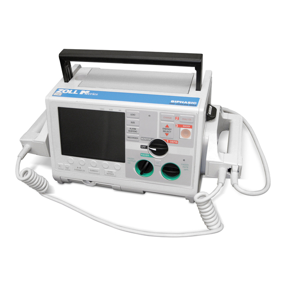
ZOLL M Series Service Manual
Hide thumbs
Also See for M Series:
- Service manual (186 pages) ,
- Manual (31 pages) ,
- Operator's manual (25 pages)
Table of Contents
Advertisement
Advertisement
Table of Contents
Troubleshooting

Subscribe to Our Youtube Channel
Related Manuals for ZOLL M Series


Summary of Contents for ZOLL M Series
- Page 1 SERVICE MANUAL ZOLL MEDICAL CORPORATION 9650-0450-01 Rev K...
-
Page 2: Warranty (U.s. Only)
ZOLL Medical Corporation's facility, whichever first occurs, the equipment (other than accessories and electrodes) will be free from defects in material and workmanship under normal use and service for the period of one (1) year. During such period ZOLL Medical Corporation will, at no charge to the customer, either repair or replace (at ZOLL Medical Corporation's sole option) any part of the equipment found by ZOLL Medical Corporation to be defective in material or workmanship. -
Page 3: Table Of Contents
.............................1 HAPTER AINTENANCE ESTS Overview ......................................1 Before You Begin the Maintenance Tests ............................2 Equipment You Need to Perform the Maintenance Tests ........................2 Equipment You Need for the M Series Options Maintenance Tests ....................3 2 ................................39 HAPTER HAPTER ..............................39 HAPTER ROUBLESHOOTING Overview ......................................39... - Page 4 1. Removing the ZIF Keeper ................................66 2. Removing the Front Panel ................................67 2A. Removing the Display .................................68 2B. Removing the Control Board ...............................69 2B. Removing the Control Board (Continued) ...........................70 3. Removing the Upper Housing Assembly ............................71 4. Removing the System Board Assembly ............................72 4.
- Page 5 12 Lead Option ....................................107 Pulse Oximetry (SpO2) ..................................108 End Tidal Carbon Dioxide (EtCO2) ..............................108 Biphasic Waveform ..................................109 ..................................113 HAPTER NDEX ................................117 HAPTER PPENDIX Overview ......................................117 Interconnect Diagram for M Series Monophasic Unit ........................118 Interconnect Diagram for M Series Biphasic Unit ...........................119...
-
Page 7: Chapter 1 Preface
Overview ZOLL Medical Corporation’s M Series Service Manual is intended for the service technician whose responsibility is to identify malfunctions and/or make repairs at the subassembly level. The Zoll M Series Service Manual has five main sections and one appendix. -
Page 8: Additional Reference Material
Safety and effectiveness data submitted by ZOLL Medical Corporation to the Food and Drug Administration (FDA) under section 510(K) of the Medical Device Act to obtain approval to market is based upon the use of ZOLL accessories such as disposable electrodes, patient cables and batteries. The use of external pacing/defibrillation electrodes and adapter units from sources other than ZOLL is not recommended. -
Page 9: Conventions
M Series Service Manual • Configuration Guide - Describes the M Series features and functions whose operation can be customized by authorized users. Conventions WARNING! Warning statements describe conditions or actions that can result in personal injury or death. CAUTION Caution statements describe conditions or actions that can result in damage to the unit. -
Page 10: Technical Service For International Customers
• Purchase Order for a unit with an expired warranty. If the unit needs to be sent to ZOLL Medical Corporation, obtain a service order request number from the Technical Service representative. Return the unit in its original container to:... -
Page 11: Chapter 1 Maintenance Tests
Because the M Series units must be maintained ready for immediate use, it is important for users to conduct the Operator’s Shift Checklist procedure at the beginning of every shift. This procedure can be completed in a few minutes and requires no additional test equipment. -
Page 12: Before You Begin The Maintenance Tests
• Complete all the steps of the procedure before evaluating the test results. Equipment You Need to Perform the Maintenance Tests For testing purposes, you can substitute an equivalent device. • Zoll Medical Electrode Adapter from Dynatech Nevada Inc. (DNI part number 3010-0378). -
Page 13: Equipment You Need For The M Series Options Maintenance Tests
® • Zoll Data Control (ZDC) for Windows software from Pinpoint Technologies, Version 1.5 or higher (no equivalent) or Zoll Data Control (ZDC) for DOS software, Version 5.5 or higher (no equivalent). • Phillips #1 screwdriver. • Phillips #2 screwdriver. - Page 14 M Series Service Manual 1.0 Physical Inspection of the Unit None. Tools Needed None. Test Setup Observe this... Pass/Fail Housing Is the unit clean and undamaged? Does the unit show signs of excessive wear? Does the handle work properly? Does the recorder drawer open and close properly?
- Page 15 Are all cables free of cracks, cuts, exposed or broken wires? 1.14 Are all bend/strain reliefs undamaged and free of excessive cable wear? 1.15 Battery Is the ZOLL battery fully charged? 1.16 Is the battery seated in the battery well correctly? Record your results on the Maintenance Test Checklist.
- Page 16 • Install the battery in the unit or connect the A/C power cord to the unit and then plug the cord into an electrical outlet. • Connect the universal cable and ECG cable (3 lead, 5 lead, or 12 lead) to the ZOLL simulator, or Dynatech Impulse 4000 Analyzer (or equivalent).
- Page 17 M Series Service Manual Do this... Observe this... Pass/Fail/NA Set the simulator to NSR of As you press the SIZE button five times (0.5, 1.0, 1.5, 2.0, 3.0), 120 BPM. To check the size note that the size of the ECG waveform appropriately changes on of the ECG waveform, the display.
- Page 18 M Series Service Manual Do this... Observe this... Pass/Fail/NA 2.11 To decrease the volume of The bar graph decreases on the display indicating a decrease in the beep, press the Dec. volume. The volume shuts off at the last bar; otherwise, the softkey.
- Page 19 M Series Service Manual Do this... Observe this... Pass/Fail/NA 2.18 If applicable, connect D/C CHARGER ON indicator lights. current and install the The amber or green lights illuminate. battery. Turn the unit off. The yellow light indicates the battery is being charged. The green light indicates the battery is fully charged to present capacity.
- Page 20 3 lead, 5 lead, and 12 lead cables. Tools Needed Test each cable separately. Note: The M Series unit must be configured to display ECG LEAD OFF message. Test Setup Connect the lead wires appropriate to each test to the Dynatech Impulse 4000 or equivalent (Symbio CS1201).
- Page 21 Set the power supply voltage to 7V. CAUTION Be sure to connect the power supply properly to the M series battery well terminals or damage to the unit may result. Do NOT raise the power supply voltage above 12V. 15 Amp...
- Page 22 M Series Service Manual Power Supply Test (continued) Test Setup for System Current Test Test Setup Do this... Observe this... Pass/Fail Turn unit to MONITOR. The unit should not turn on. Turn the unit off. Adjust the power supply The unit should turn on.
- Page 23 M Series Service Manual Set voltage scale (if DVM is not autoranging) to 220 mV. Battery Well 15 Amp Supply Black Do this... Observe this... Pass/Fail/NA System Current Test Set power supply to 10.3V.
- Page 24 M Series Service Manual Do this... Observe this... Pass/Fail/NA Set Selector Switch to Voltage across resistor should be 80 mV or less (<800 mA of ON Monitor (ON for AED). current). NOTE: Without optional parameters. a) With green screen or LCD and no options <80mV b) With yellow screen and no options <81mV...
- Page 25 M Series Service Manual Measure voltage across resistor. Do this... Observe this... Pass/Fail 4.10 Off Current Test Voltage should be less than 450 mV (<450 µ A of current). Measure across resistor with unit turned off. Record your results on the Maintenance Tests Checklist.
- Page 26 M Series Service Manual 5.0 Leakage Current Test See the manufacturer’s instructions or supplied specifications for the leakage tester you use. Tools Needed See the manufacturer’s instructions or supplied specifications for the leakage tester you use. Repeat leakage test with Setup accessories: MFC, external paddles, internal paddles, and anterior/posterior paddles.
- Page 27 M Series Service Manual 6.0 Paddles Test None. Tools Needed If applicable, connect the universal cable to the paddles. Place paddles in paddle wells. Test Setup Do this... Observe this... Pass/Fail/NA The energy selection decreases to 1J. Turn the selector switch to DEFIB.
- Page 28 M Series Service Manual 7.0 Heart Rate Display Test Calibrated ECG simulator with 60Hz sine wave output capability. Tools Needed Mini-phone plug for measuring output signal from 1 Volt ECG OUT jack (optional). ECG Cable (3 or 5 leads). Turn the selector switch to MONITOR. Press LEAD button until “I” displays.
- Page 29 M Series Service Manual 8.0 Calibrating Pulses on Strip Chart Test None. Tools Needed None. Test Setup Do this... Observe this... Pass/Fail/NA Press the RECORDER button. Press and hold SIZE button The strip chart displays a signal of 300 ppm with an amplitude of to activate the calibration 10 mm +/- 1 mm.
- Page 30 M Series Service Manual 9.0 Notch Filter Test Dynatech Impulse 4000 (or equivalent). Tools Needed Connect the ECG cable to the DYNATECH Impulse 4000 or equivalent. Test Setup Connect the ECG cable to the unit Do this... Observe this... Pass/Fail/NA Turn the selector switch to MONITOR mode.
- Page 31 M Series Service Manual 10.0 Heart Rate Alarm Test Dynatech Impulse 4000. Tools Needed Do this... Observe this... Pass Fail/NA 10.1 Turn the selector switch to Lead II message displays. MONITOR. (ON for AED. Select NSR ECG at 120 BPM +/- 2 displayed.
- Page 32 M Series Service Manual Do this... Observe this... Pass Fail/NA 10.10 Reattach ECG Lead wire to The bell symbol has an “X through it. Dynatech Impulse 4000 and hold the The heart symbol flashes with each QRS wave. ALARM SUSPEND button on unit for 4 seconds.
- Page 33 M Series Service Manual 11.0 Defibrillator Self Test SHOCK HAZARD! TAKE THE NECESSRY PRECAUTIONS TO GUARD AGAINST SHOCK OR INJURY BEFORE YOU START CONDUCTING THE DEFIRBILLATOR TESTS. Keep hands and all other objects clear of the multi-function cable connections and defibrillator analyzer when discharging the defibrillator.
- Page 34 M Series Service Manual Do this... Observe this... Pass/Fail 11.2 Connect the universal cable DEFIB PAD SHORT message displays. to the MFC test port. 11.3 Select energy level of 100J The charge time is >2 second and <10 seconds and SELECT 30J and press the CHARGE FOR TEST is displayed.
- Page 35 M Series Service Manual 12.0 Synchronized Cardioversion Test Dynatech Impulse 4000 or equivalent defibrillator analyzer. Tools Needed Connect the universal cable via the adapter (D.N.I #3010-0378) to the defibrillator analyzer. Test Setup Select cardioversion on analyzer. Input 1mV ECG signal at 60 -120 BPM.
- Page 36 Connect the universal cable via the adapter (D.N.I #3010-0378) to the defibrillator analyzer. Ensure that a fully charged battery is installed in the unit. If your M Series AED does not have manual override capability, do not do this test. NOTE: Do this...
- Page 37 M Series Service Manual Do this... Observe this... Pass/Fail/NA 13.6 Press ENERGY SELECT DEFIB 360J SEL displays up arrow until 360J (200J for Biphasic) displays. DEFIB 200J SEL displays (for Biphasic unit). 13.7 Press CHARGE button and Observe and record the value of the charge time on the stop start timing with a watch.
- Page 38 M Series Service Manual 14.0 Summary Report Test (if applicable) None. Tools Needed Connect the universal cable to the defibrillator analyzer. If you are using paddles, place the paddles on the analyzer’s Test Setup discharge plates. Do this... Observe this...
- Page 39 M Series Service Manual 15.0 Advisory Message Test (for AED and Manual/Advisory Units) None. Tools Needed Connect the universal cable via the adapter (D.N.I #3010-0378), then attach to the defibrillator analyzer. Test Setup Do this... Observe this... Pass/Fail 15.1 Connect universal cable to the simulator.
- Page 40 Dynatech Impulse 4000 equivalent. Note: The following tests are to be performed only on M Series units equipped with the optional pacing function. The pacer output can be measured using an oscilloscope set to DC coupling connected across a load resistor. (See diagram in column for universal cable connector polarity.) The load resistor is a 100 ohm, 5 watt or greater.
- Page 41 M Series Service Manual Do this... Observe this... Pass/Fail 16.4 Increase the output to Output on the Dynatech Impulse 4000 is 20mA +/- 5mA. Pulse 20mA. width is 40mS +/-2mS. 16.5 Increase the output to Output on the Dynatech Impulse 4000 is 40mA +/- 5 mA. Pulse 40mA.
- Page 42 Pacer rate on Dynatech is 49-51 ppm. ppm. 16.19 Connect the ECG cable to ECG at 60 BPM is seen on the display and no stimulus markers. the M Series and Dynatech Impulse 4000. Select the ECG at 60 BPM on the Dynatech Impulse 4000. 16.20...
- Page 43 17.3 Press the 02+ or 02- softkey The M Series reading of 98 +/- 1% appears on the M Series of the simulator until the monitor. Note that you may need to wait up to 2 minutes for the output is at 98%.
- Page 44 ZOLL display. heart rate is 230 BPM. saturation of 96-100% appears on the M Series display. The heart rate of 226-234 BPM displays on the M Series monitor. 17.5 Using the Index saturation of 96-100% displays on the unit.
- Page 45 M Series Service Manual Do this... Observe this... Pass/Fail 17.11 Remove the Masimo patient cable. Record your results on the Maintenance Tests Checklist.
- Page 46 Manual mode.) 18.2 Attach the EtCO simulator SENSOR WARMUP message displays. to the M Series input Note: You may need to wait up to 5 minutes for the warm-up connections. message to disappear. If the message REPLACE CO SENSOR displays, reinsert the Novametrix Simulator Cable.
- Page 47 CELL. 18.4 On the Novametrix The EtCO reading of 74-84 mmHg appears on the M Series Simulator, set SENSOR display. Note that you may need to wait up to 10 seconds for the LOCATION to AA CELL. unit to stabilize.
- Page 48 M Series Service Manual...
-
Page 49: Chapter 2 Troubleshooting
This chapter describes the most common technical problems that biomedical technicians experience when checking the M Series during routine maintenance or when there is a malfunction of the unit. It also contains a list of error messages that users may see if the unit is not operating properly. -
Page 50: Troubleshooting
M Series Service Manual Troubleshooting The following tables show the most common troubleshooting issues and their solutions. First, attempt to solve the problem with “Recommended User Action.” If these steps do not solve the problem, follow the steps listed in the “Recommended Technical Action” column. - Page 51 • Remove and replace the High Voltage Module. properly. • Remove and replace the system board. • If the DEFIB PAD SHORT message • Call ZOLL Technical Support for assistance. displays, then check the connections of the pads to the patient and to the defibrillator cable.
- Page 52 M Series Service Manual Reported Problem Recommended User Action Recommended Technical Action Flash or arcing under defibrillator • Avoiding using alcohol and betadine in and • Wet gel pads must be stored flat. pad. around the treatment area because these...
- Page 53 90% of electrode issues, size and lead changes don’t help. Electronic interference. Check for possible excessive radio frequency Turn off sources of excessive RFI. interference. Move M Series unit away from RFI source. Move patient cables away from other electrical equipment.
-
Page 54: Zoll M Series Error Messages
Zoll M Series Error Messages The following is a list of Zoll M Series error messages that may appear on your display. The “User Advisory” column informs you about an action in progress or provides feedback on a user correctable situation that typically does not require further technical support. - Page 55 M Series Service Manual User Error Message Explanation Technical Action Advisory ANALYSIS RESTARTED This is a user prompt issued simultaneously with ECG TOO LARGE or ECG TOO SMALL. Device detected ECG signals out of range, automatically adjusted ECG size and is now restarting its shockable rhythm analysis sequence.
- Page 56 M Series Service Manual User Error Message Explanation Technical Action Advisory BATT OVERCHARGE Charger on for > 4 hours. Replace battery and or charger. BRIDGE SHORT Current higher than expected was detected during the Ensure pads/paddles Biphasic bridge test or immediately following a are used properly.
- Page 57 M Series Service Manual User Error Message Explanation Technical Action Advisory REPLACE CARD Write errors during manual or semi-automated May have configuration modes. card installed or write protection on. CARD FULL Memory Card Full. CHECK CO SENSOR EtCO Sensor is unplugged or defective.
- Page 58 M Series Service Manual User Error Message Explanation Technical Action Advisory CHECK RECORDER Produced when paper tray is empty, paper jams or Replace paper sensor recorder door is opened. board, system interconnect board, and/or system board. CHECK SPO SITE Low or no perfusion in monitored finger or toe.
- Page 59 M Series Service Manual User Error Message Explanation Technical Action Advisory DEFIB FAULT 71 More than 50 internal dumps occurred in less than 20 Turn the unit to OFF minutes. and back on. If fault persists, replace high voltage module.
- Page 60 M Series Service Manual User Error Message Explanation Technical Action Advisory DEFIB FAULT 86 One discharge switch closed during power up test. Replace paddles, control board or system board. DEFIB FAULT 87 Both discharge switches closed during power up test.
- Page 61 M Series Service Manual User Error Message Explanation Technical Action Advisory DEFIB PAD SHORT Measured impedance between high voltage leads of Ensure pads are MFC. coupled to patient. Check /replace pads or universal cable. Replace system board. DISABLE SYNC Sync mode active when analyze pressed in defib.
- Page 62 M Series Service Manual User Error Message Explanation Technical Action Advisory ECG V2 LEAD OFF Chest lead V2 is not properly attached to patient. Reattach V lead. Check cable. ECG V3 LEAD OFF Chest lead V3 is not properly attached to patient.
- Page 63 M Series Service Manual User Error Message Explanation Technical Action Advisory FAX SENDING Transmitting fax. INSERT CARD No card installed in unit during manual or semi- Check memory card automated modes. LOW BATTERY Low battery. Replace battery or plug into AC power. Replace charger.
- Page 64 M Series Service Manual User Error Message Explanation Technical Action Advisory PACER FAULT 116 Failure to detect XPACE_ON. Replace high voltage module, capacitor, and/ or system board. PACER FAULT 117 Pace relay is stuck closed. Replace high voltage module, capacitor, and/ or system board.
- Page 65 M Series Service Manual User Error Message Explanation Technical Action Advisory POOR LEAD CONTACT One or more ECG leads are poorly connected or not Check electrode connected to patient. (User configurable.) attachment to patient, cable connector to electrode, cable to unit connector.
- Page 66 M Series Service Manual User Error Message Explanation Technical Action Advisory RECORDER FAULT 143 Strip chart failed power-up echo test. Check paper tray and Communications error. paper path. Replace the system interconnect board and/or the system board. Turn unit off and back on again.
- Page 67 M Series Service Manual User Error Message Explanation Technical Action Advisory RESERVED 1 The watchdog timer is not functional in the unit. Turn off unit and then turn on to reset. If fault persists, replace system board. RETRY ANALYSIS Advisory message in conjunction with noisy ECG.
- Page 68 M Series Service Manual User Error Message Explanation Technical Action Advisory AMBIENT LIGHT Ambient light is too bright. Shield sensor from ambient light. Replace sensor. Replace module COMM ERR No transmissions from SpO unit received. Replace Sp0 module Communication error or no communication from and/or system board.
- Page 69 M Series Service Manual User Error Message Explanation Technical Action Advisory SYSTEM FAULT 6 No communications received from ECU for 4 Turn off unit and then seconds. turn on to reset. If fault persists, replace system board. SYSTEM FAULT 7 The A/D converter is not performing conversions in Replace system board.
- Page 70 M Series Service Manual User Error Message Explanation Technical Action Advisory USE PADS TO PACE External paddles detected in pace mode. USE ROOM AIR Adapter zeroing started with EtCO in the adapter or Place CO sensor on ADAPTER the adapter is on the REF or “0” cell.
-
Page 71: Chapter 3 Disassembly Procedures
Chapter 3 Disassembly Procedures Overview This chapter provides instructions on how to disassemble and reassemble the M Series unit. • Equipment You Need for the Disassembly Procedures • Parts That May Need Replacing After Disassembly • Safety Precautions You Need to Take •... -
Page 72: Equipment You Need For The Disassembly Procedures
• Pacer/Output/Rate knob replacement (ZOLL Part Number 9310-0520) If you are removing the Battery Interconnect Board, you may need to replace it with a new one, using ZOLL Part Number 9301-0302, if connectors have been UV welded as in older M Series models. -
Page 73: Safety Precautions You Need To Take
M Series Service Manual Safety Precautions You Need to Take WARNING! SHOCK HAZARD! CAUTION TAKE THE NECESSARY PRECAUTIONS TO GUARD AGAINST SHOCK OR INJURY BEFORE YOU CONDUCT DEFIBRILLATOR TESTS OR REPAIRS. • Only properly trained technicians should service the unit. -
Page 74: Overview Of Modules
M Series Service Manual Overview of Modules The M Series has 14 modules. These modules are shown below. module with bracket for System Board Assembly Isolated Power Supply with EtCO EtCO System Interconnect Board AC Charger Assembly Battery Interconnect Board Assembly... - Page 75 M Series Service Manual Control Board (from Front Panel) High Voltage Module Assembly High Voltage Capacitor Assembly PCMCIA Card Slot Recorder Motor Module (without bracket) Isolated Power Supply for SpO Module Biphasic Capacitor and Bridge Assembly...
-
Page 76: Removing The Zif Keeper
M Series Service Manual 1. Removing the Step 1: The connector must be facing you as shown in the diagram. ZIF Keeper • Orange stick Note: It is important to know this procedure before you start disassembling the unit. Removing the ZIF (Zero Insertion Force) Keeper incorrectly can damage the unit’s system board. -
Page 77: Removing The Front Panel
M Series Service Manual 2. Removing the Step 1: Remove the battery from the battery well Step 2: Rotate unit on to its back side. Remove the and place it in front of the unit. two Phillips head screws located on the left and right sides on the bottom of the unit. -
Page 78: Removing The Display
M Series Service Manual 2A. Removing the Step 1: Remove the grounding copper tape from the Step 2: Remove the Video Display Assembly by outer display shield. rotating the display upwards from the lower portion of the display panel assembly. -
Page 79: Removing The Control Board
Step 3: Rock the foam packaging back and forth from Step 4: Remove the panel overlay circuit cable from • Main Selector knob replacement (ZOLL Part the control panel board to remove the foam. the control board by lifting the sides of the lock lever located under the front of the control board. -
Page 80: Removing The Control Board (Continued)
M Series Service Manual 2B. Removing the Step 5: Disconnect the speaker microphone cable. Step 6: Remove the 50 pin laminate cable from the Remove the Control Panel Board from the Front control board. See 1.0 Removing the ZIF Keeper. -
Page 81: Removing The Upper Housing Assembly
M Series Service Manual 3. Removing the Step 1: Remove two screws from the back side of the Step 2: Secure lower housing to the table by pressing Upper Housing Assembly and three screws from the downward in the paddle well. Using the carry handle, front. -
Page 82: Removing The System Board Assembly
M Series Service Manual 4. Removing the Step 1: Using needle nose pliers, remove left and Step 2: Remove the two wire speaker cable (if right multi-wire cables on the back side of the system applicable). board. To avoid damage to the cable, do not pull the System Board wires. -
Page 83: Removing The System Board Assembly (Continued)
M Series Service Manual 4. Removing the Step 5: Remove the ZIF Keeper. (See 1. Removing the Step 6: For Biphasic M Series units only: Remove the ZIF Keeper.) 20 pin power cable by lifting the slide locking tab upwards. -
Page 84: Removing The Battery Interconnect Board Assembly
M Series Service Manual 5. Removing the Step 1: Identify the Battery Interconnect Board. Step 2: Remove the wide laminate cable from the high voltage module connector by lifting the cable vertically. Battery Interconnect Board Assembly Tools Required • Orange stick Setup Step 3: Remove the push pin and small insert collar. -
Page 85: Removing The High Voltage/Charger Assembly
M Series Service Manual 6. Removing the Step 1: Remove the High Voltage/Charger Assembly Step 2: Set the Assembly on the table. Pull apart the from the main housing by lifting the High Voltage/ High Voltage Module from the Charger Assembly. -
Page 86: Removing The High Voltage/Charger Assembly (Continued)
M Series Service Manual 6. Removing the Step 5: Lift the SpO module straight up from the Step 6: (Biphasic units only) Disconnect the biphasic foam and disconnect the ribbon cable from the defibrillator capacitor from the rear panel connector. -
Page 87: Removing The High Voltage Module Assembly
M Series Service Manual 7. Removing the Step 1: Remove the signal cable from the High Step 2: Remove the Kapton tape on the bottom of Voltage module. the foam surrounding the High Voltage Module. High Voltage Module Assembly Tools Required •... -
Page 88: Removing The High Voltage Capacitor Assembly
M Series Service Manual 8. Removing the Step 1: Open the High Voltage Capacitor plastic Step 2: Bleed the excess voltage using a resistor with Mylar tape. isolator by lifting the values of approximately 5 kohms, 25 watts for 10-20 seconds. -
Page 89: Removing The System Interconnect Board
M Series Service Manual 9. Removing the Step 1: Remove the clear plastic head isolater. Step 2: Remove two screws from each side of the System Interconnect Board. System Interconnect Board Tools Required • #2 Phillips screwdriver Step 3: Disconnect the cables and lift the System Setup Interconnect Board out of the unit. -
Page 90: Removing The Printer/Recorder Motor
M Series Service Manual 10. Removing the Step 1: Using the needle nose pliers, carefully lift the Step 2: Remove the motor bracket mounting screw spacer block upwards. Printer/Recorder cable Motor spacer block Tools Required • #2 Phillips screwdriver • Exacto-Knife motor •... -
Page 91: Removing The Lower Housing Assembly
M Series Service Manual 11. Removing the Step 1: Remove the paper tray by pulling it out and Step 2: Remove the screw at the bottom of the unit to pressing the locking tab upwards at the rear of the remove the PCMCIA FAX/Modem card’s plastic... -
Page 92: Removing The Print Head Assembly
M Series Service Manual 12. Removing the Step 1: Remove two screws from the paper tray Step 2: Disconnect the ribbon cable from the print guide and remove the paper tray guide. head. Print Head print head ribbon cable Assembly Tools Required •... -
Page 93: Removing The Pcmcia Card Slot Assembly
M Series Service Manual 13. Removing the Step 1: Remove the two screws holding the card slot retainer. Lift up card slot assembly. PCMCIA Card Slot Assembly Tools Required • #2 Phillips screwdriver Setup • Remove the Lower Housing. To reinstall the PCMCIA card slot, reverse the... -
Page 94: Removing The Paddle Release Latch
M Series Service Manual 14. Removing the Step 1: Using the Exacto Knife, remove the Step 2: Insert the screwdriver into the opening under the adhesive seal. adhesive seal on the unit’s chassis. Paddle Release Latch Tools Required • #2 Phillips screwdriver •... -
Page 95: Chapter 1 Replacement Parts
To order by mail from ZOLL Medical Corporation, address your request to: ZOLL Medical Corporation 32 Second Avenue Burlington, MA. 01803-4420 Attention: Technical Service Department 1-781-229-0020; 1-800-348-9011; Fax: 1-781-229-0758 ZOLL reserves the right to substitute different parts to reflect modifications and improvements in ZOLL M Series Note circuitry and design. -
Page 96: Replacement Parts
M Series Service Manual Replacement Parts Description Part Number 12 Lead ECG Cable 1001-0031-01 3M 12 Conductor Cable - LCD 0500-6000 4-40 x 1/4, System Interconnect Board, Mounting Screw 0163-0626 4-40 x 3/8 Modem Bezel Screw 0163-0153 6/32 x 3/8 Screws, Housings... - Page 97 M Series Service Manual Description Part Number Bracket, Speaker Mount 9320-0409 Brush, Static Dissipation 9340-0102 Bumper, Chassis, High Voltage, Capacitor 9330-0205 Cable Flex CRT. 312 TO System Board 9500-0519 Cable Laminate, 50 Pin 9500-0501 Cable, Laminate, ECG Connector to System Board...
- Page 98 M Series Service Manual Description Part Number Gasket, MPPM Port and Motor Support, Chassis 9330-0303 Gasket, PCMCIA Connector, System Interconnect Board 9330-0312 Gasket, Print Head Cable 9330-0314 Handle (Part One) 9310-0545 Handle Insert (Part Two) 9310-0546 Isolator, High Voltage Module, Folded...
- Page 99 M Series Service Manual Description Part Number Motor Support (Teflon Piece) 9330-0355 M Series Main Label Set 9305-0527-01 Noncharger Substitute Board 9301-0311 O-ring, MFC, M Series 0160-6950 Paddle Shoes 1001-0148 Paper Tray Assembly 1001-0103 PCMCIA Conn., Assembly 3001-0101 PCMCIA Stabilizer Board...
-
Page 100: Field Replacement Parts
M Series Service Manual Description Part Number Tape, Kapton, Roll (108') 0550-0003 Tape, Yellow Mylar, Roll (108') 0550-0125 Universal cable 1001-0196-01 Upper Housing 1001-0126 Upper Latch Seal 9330-0304 Field Replacement Parts Description Part Number ts EtC0 Battery Interconnect for uni... - Page 101 M Series Service Manual Description Part Number EtCO Battery Interconnect (pre 9301-0302 Paper Sensor Board 1001-0131 System Interconnect 9301-0306 AC Charger Board with Heatsink 1001-0108 Control Board with Pace 9301-0312 LCD Display Interface Board 9301-0308 Board (Masimo) 1001-0158 Power Supply, Isolated, SpO...
- Page 102 M Series Service Manual Description Part Number 12 Lead Based (9301-0337-01) 1001-0130-09 3/5 Lead With Audio 9301-03 37-02 and 9301-0304 1001-0130-10 12 Lead (9301-0307-01) 1001-0130-06 3/5 Lead/Biphasic (9301-0307-02) 1001-0130-07 System Interconnect Board with Faxing Capability 9301-0306-03 PCB control without pace non AED...
-
Page 103: Chapter 4 ............................................................................................................................................................. C Hapter 5
Chapter 5 Functional Description Overview This chapter provides functional descriptions of the components contained in the ZOLL M Series and the M Series options. Refer to the interconnect diagram that delineates the different components of the defibrillator. This chapter includes:... -
Page 104: Main System Board
Biphasic Module Main System Board The M Series electrical circuitry consists of several functional modules. Each module is physically located on one or more of the printed wiring board assemblies (PWBA). In some cases, a functional module is distributed across several assemblies within the unit. - Page 105 M Series Service Manual Refer to the M Series Interconnect diagram to identify unit components described in this manual. ODULE OCATION Main Central Processing Unit (CPU) and ECU Main System PWBA Pacer/Defib Charging and High Voltage High Voltage Module Control (Defib/Pace)
-
Page 106: Main System Board Functions
M Series Service Manual Main System Board Functions The Main System Board contains the major computing and control elements for the M Series unit. The printed wiring board assembly (PWBA) receives signals from the front panel control switches, ECG input connectors and functional... - Page 107 M Series Service Manual Summary Report, 12 Lead ECG Reports data storage. Monitoring of battery status and control over Battery Charging functions performed by the AC or DC Charger PWBA. Data transmission to and control over the System Interconnect PCB functions, including the stripchart recorder...
-
Page 108: Power Supply
The power supply converts DC power from a removable battery or the AC/DC Battery Charger module to voltages required by the M Series hardware. The power supply circuit converts the raw battery or the Charger PWBA output voltages of +8.5 VDC to +16 VDC into the voltages shown in the table below, including load and line regulation. -
Page 109: Ecg Front End
M Series Service Manual ECG Front End The ECG front end provides an electrically isolated serial interface between the main system board functions and patient interface ECG connectors. It performs the following: • Analog ECG amplification and signal conditioning. • Pacemaker pulse detection. -
Page 110: High Voltage Module
M Series Service Manual as data protection and virtual memory functions. It also has a timer, a real time clock, an interrupt controller, a serial communication interface (SCI), and other peripheral functions necessary for the system operation. The memory circuitry includes Flash ROM, internal flash non-volatile memory and DRAM. -
Page 111: Defibrillator Charging And Discharging
Unlike previous ZOLL designs that isolated the patient from defib circuitry via an electromechanical patient relay, the M Series utilizes a bank of silicon-controlled rectifiers (SCRs). As the defibrillator capacitor is charged, the voltage is monitored via R1 - R4, which drive differential amplifiers referred to the system ground. These resistor dividers split... -
Page 112: High Voltage Capacitor Monitor
If the M Series is in the self-test mode, the energy is delivered internally. The microprocessor calculates the actual delivered energy from the current waveform and displays a TEST OK message on the display, if the self-test meets the appropriate criteria. -
Page 113: Pacer/Defibrillator Control Signals
M Series Service Manual The Pacer circuit produces and delivers user-controllable pace pulses to the pacing electrodes. To initiate pacing, the front panel switch is turned to PACER and the OUTPUT and RATE controls are set. Pacing current amplitude is constant during the pulse and is determined by the position of the front panel PACER OUTPUT dial. - Page 114 M Series Service Manual NALOG OLTAGE PERATION OMMENT VCTL Analog control voltage scaled Only active in pace mode. 0 - 2.5 V for pace current of 0 - 140 ma. FET_MON Analog voltage monitors the Provides a signature condition of the discharge voltage in case of a fault.
-
Page 115: Ac/Dc Charger Module
(for a mains input), AC-DC and DC-DC conversion and isolation barrier between the M Series and power sources. This module also provides the power necessary to run the M Series in any mode of operation, as well as providing additional charging current to the battery. When the M Series is turned off but connected to an external AC or DC source, the charger module controls battery charging currents and voltages needed to charge the M Series battery. -
Page 116: System Interconnect Module
M Series Service Manual System Interconnect Module The system interconnect PWBA receives signals from the Main System Board and in turn controls operation of the stripchart recorder and PCMCIA functions. Stripchart Recorder The Stripchart Recorder module includes a microprocessor, serial interface to the main system board and circuitry which drive the stripchart recorder’s motor and printhead in response to the main CPU signals. -
Page 117: M Series Options
The 12 lead cable is required to produce 12 lead reports. M Series unit must have the 12 lead option installed. All limb leads and at least one V-lead must be connected to initiate a 12 lead acquisition. Printed 12 Lead bandwidth is user configurable to be either 0.05-150 Hz (per AAMI EC11) or 0.05-40 Hz. -
Page 118: Pulse Oximetry (Spo2)
Circuit Board) connects to the Masimo sensors and reports monitoring results (oxygen saturation, pulse rate, pulse waveform, etc.) via a serial digital interface to the M Series system board. The M Series system provides isolated DC power and serial communication to the SpO Board via the Isolated Power Supply board. -
Page 119: Biphasic Waveform
, and respiration rate data. The M Series software formats the data for output to the display and strip chart recorder. In addition, the M Series software performs range checking of the Novametrix data to determine the presence of low or high EtCO and respiration rate alarm limit violations. - Page 120 The ZOLL Biphasic units produce a rectilinear waveform whose shape remains essentially constant from patient to patient. The rectilinear biphasic waveform consists of a 6 millisecond, essentially constant current first phase followed by a 4 millisecond, truncated exponential second phase.
- Page 121 M Series Service Manual The following Rectilinear Biphasic Waveform is produced when the M Series with Biphasic option is discharged into a 50 ohm load at the default energy setting of 120 joules. The vertical axis is in amperes; the horizontal axis is in...
- Page 122 M Series Service Manual...
-
Page 123: Chapter 1 Index
M Series Service Manual Index CABLE FAULT message 45 DEFIB FAULT 95 message 49 CANNOT CHARGE 45 DEFIB FAULT 96 message 49 CANNOT CHARGE message 45 DEFIB NOT CHARGED message 49 CHECK 47 DEFIB PAD SHORT 40 CHECK PADS/POOR PAD CONTACT message 40... - Page 124 M Series Service Manual CANNOT CHARGE 45 EtCO2 LOW BATTERY message 52 CHECK RECORDER 47 Isolated Power Supply Assembly 108 CLOCK FAULT 12 47 EtCO2 COM ERROR message 51 CLOCK FAULT 13 47 EtCO2 Isolated Power Supply Assembly 96 M Series 65...
- Page 125 RETRY ANALYSIS message 56 ZERO CO2 ADAPTER message 59 Technical Service Department ZERO CO2 SENSOR message 59 Address 86 Zoll M Series Text Messages 39 Safety Consideration i Test 6, 10, 11 ZOLL Medical Corporation Safety Precautions 64 3, 5, and 12 Leads 10...
- Page 126 M Series Service Manual...
-
Page 127: Chapter 4 Appendix
M Series Service Manual Appendix Overview This appendix includes: • ZOLL M Series Interconnect diagrams • ZOLL M Series Maintenance Tests Checklist Photocopy the ZOLL M Series Checklist to use it for your six month maintenance checklist of the M Series equipment. -
Page 128: Interconnect Diagram For M Series Monophasic Unit
M Series Service Manual Interconnect Diagram for M Series Monophasic Unit... -
Page 129: Interconnect Diagram For M Series Biphasic Unit
M Series Service Manual Interconnect Diagram for M Series Biphasic Unit... - Page 130 M Series Service Manual...
- Page 131 Serial #__________________ Location __________________ Test Date___/___/___ ZOLL M Series Maintenance Tests Checklist Tester____________________________ Signature__________________________ Inspection Test Front Panel Button Test Leads Test Calibrating Pulse Test Defibrillator Self Test Pass Fail Pass Fail Pass Fail Pass Fail Pass Fail Result of Check: 11.1...
- Page 132 Serial #__________________ Location __________________ Test Date___/___/___ ZOLL M Series Maintenance Tests Checklist Tester____________________________ Signature__________________________ Summary Report Test Pacer Test Monitor Test Pass Fail Pass Fail Pass Fail 14.1 16.1 17.1 14.2 16.2 17.2 14.3 16.3 17.3 14.4 16.4 17.4 16.5 17.5...
Need help?
Do you have a question about the M Series and is the answer not in the manual?
Questions and answers