Table of Contents
Advertisement
Quick Links
Advertisement
Table of Contents

Related Manuals for KLS Martin group MCO25plus

Summary of Contents for KLS Martin group MCO25plus
- Page 1 Laser System MCO25plus Operating Instructions and Technical Description...
-
Page 2: Table Of Contents
MCO25plus Operating Instructions Table of Contents Product Liability and Warranty ............6 Safety Instructions ..............7 2.1 General Provisions ................7 2.2 Laser Safety ..................9 2.3 Explosion and Fire Hazards..............10 2.4 Protecting the Patient ................. 11 ... - Page 3 MCO25plus Operating Instructions 4.5 Connecting the Articulated Mirror Arm ..........25 4.5.1 Preparing the Laser Unit ................26 4.5.2 Unpacking the Articulated Mirror Arm .............. 27 4.5.3 Mounting the Articulated Mirror Arm ............... 28 ...
- Page 4 MCO25plus Operating Instructions 6.5.1 Parameters in Superpulse Mode ..............51 6.6 Scanner Operation* ................51 6.6.1 Mounting the Scanner ................... 51 6.6.2 Articulated Mirror Arm for Scanner Operation ........... 54 6.6.3 Display ....................... 55 ...
- Page 5 MCO25plus Operating Instructions Quick Reference Guide ............... 86 10.1 Preparatory Measures/Checks .............. 86 10.2 Switching on the Unit ................. 86 10.3 Setting Parameters ................87 10.4 Performing the Therapy ..............87 10.5 Switching off the Unit ................. 87 ...
-
Page 6: Product Liability And Warranty
MCO25plus Operating Instructions Product Liability and Warranty Gebrüder Martin will accept no responsibility for the safety, reliability and proper functioning of the unit unless: • all readjustments, modifications or repairs that become necessary are carried out by persons authorized to perform such work, •... -
Page 7: Safety Instructions
MCO25plus Operating Instructions Safety Instructions The following provisions and recommendations are based on: DIN EN 60825-1 (2003-10) Safety of laser products – Part 1: Equipment classification, requirements and user’s guide DIN EN 60601-1 (1996-03) Medical electrical equipment – Part 1: General requirements... - Page 8 Moreover, the following supplementary provisions should be observed: • The MCO25plus may be operated only by qualified and duly authorized personnel. These persons must be fully familiar with the laser system and have a complete understanding of all safety measures required. The names of these authorized persons must be recorded in the medical device logbook.
-
Page 9: Laser Safety
MCO25plus Operating Instructions Accidents involving personal injuries must be reported to the appropriate authority without delay. Laser Safety This unit is a Class IV laser, which means that both the laser beam as such and the diffuse laser light reflected from surfaces may be harmful. -
Page 10: Explosion And Fire Hazards
This increases the reactivity of the irradiated material. When working with the MCO25plus, the user therefore is required to observe the following measures in order to prevent laser-induced fires and explosions: •... -
Page 11: Protecting The Patient
Treatment Room Requirements • All rooms in which the MCO25plus is used must be marked at the entryways/doors with a laser radiation warning sign (see “laser star” symbol provided in the accessories kit). •... -
Page 12: Pilot Laser Safety Instructions
MCO25plus Operating Instructions • If the laser unit is found to be in any way defective, the findings must be duly entered in the device logbook and reported to the Laser Safety officer. Besides, either Gebrüder Martin or a service technician authorized by Gebrüder Martin to carry out repairs should be contacted as soon as possible. -
Page 13: Laser Safety Officer
MCO25plus Operating Instructions by blowing away any smoke (so-called laser plume) produced during laser application. A smoke evacuator is used to remove the smoke altogether from the surgical site. This can either be a fixed-installation device for exclusive use in the laser room, or a separate unit operated in conjunction with the laser. -
Page 14: Grounding The Unit
MCO25plus Operating Instructions 2.12 Grounding the Unit The unit is grounded via the grounding conductor integrated in the power cord. This is an important prerequisite for the safe operation of the unit. If the power cord is connected to the supply source in accordance with the relevant electrotechnical regulations, proper grounding is automatically ensured. - Page 15 MCO25plus Operating Instructions To ensure that the irradiation parameters selected cannot be accidentally changed during the laser treatment, all control-panel buttons are blocked (inoperable) as long as the footswitch is held down. A microprocessor helps to keep the laser output power at a constant level (in accordance with the value selected, and within system-specific tolerance limits).
-
Page 16: Rating Plate And Warning & Information Labels
MCO25plus Operating Instructions 2.16 Rating Plate and Warning & Information Labels Figures 2.1, 2.2 and 2.3 show the rating plate and the warning and information labels affixed to the laser unit (including label position). Visible and invisible LASER RADIATION! Avoid skin or eye contact... - Page 17 MCO25plus Operating Instructions Max. power: 30 W Max. peak power: 250 W (superpulse) Pulse length: 3 ms – 10 s Wavelength: 10,600 nm Pilot laser wavelength: 635 ± 10 nm Pilot laser power: 3 mW Laser class: 4 (DIN EN 60825-1: 10.03) Fig.
-
Page 18: Nominal Ocular Hazard Distances (Nohd)
76-100-15 Special optics set for nasal 14 m Cannula, straight or 76-600-00 operations angled Soft Scan Plus scanner Handpiece, f = 127 mm 76-500-30 Handpiece, f = 200 mm 76-500-60 Table 2.1: Safety distances (NOHD) for MCO25plus accessories V 4.1... -
Page 19: Description Of The Unit
MCO25plus Operating Instructions Description of the Unit Some General Remarks on the Laser Principle LASER is an acronym meaning “Light Amplification by Stimulated Emission of Radiation”. The laser (light source) consists of an active medium and an excitation source. This excitation source transforms (“pumps”) the active medium from its normal state into a stimulated energy... -
Page 20: Range Of Application
(among other factors, water content and perfusion rate) The application possibilities of the Martin MCO25plus are numerous. Apart from a low penetration depth and a precise cut, its laser-surgical advantages include low patient strain and fast wound healing. -
Page 21: General Description Of The System
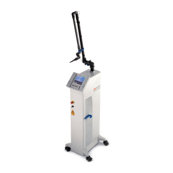
System Design Options The MCO25plus is available in two versions: with or without scanner. Thanks to the system’s modular design, the performance characteristics of both versions are fully identical. As a scanner can be conveniently added by installing just a few additional components, the modular concept allows easy upgrading of the scannerless system anytime later. - Page 22 MCO25plus Operating Instructions Fig. 3.1 KLS Martin MCO25plus standard version Focusing handpiece, f = 127 mm Articulated mirror arm Display and controls Emergency stop switch Keylock switch Front castors with locking device Rear castors Footswitch holder (retaining pin) V 4.1...
-
Page 23: Installation
Laser Location Fig. 3.1 shows the MCO25plus laser system, which has a weight of 57 kg and can be easily moved on its wheels (castors). -
Page 24: Rear Side Of The Unit (With Connections)
MCO25plus Operating Instructions Rear Side of the Unit (with Connections) Fig. 4.1 Rear panel of the laser unit Rating plate (nameplate) Footswitch connector socket Power supply socket Cord retaining clamp OR door interlock Equipotential bonding pin Line fuses 4.4.1 Rating Plate (Nameplate) The rating plate (1, Fig. -
Page 25: Or Door Interlock
MCO25plus Operating Instructions 4.4.5 OR Door Interlock An external door contact may also be integrated into the safety system. When using this device, the laser immediately goes into “STANDBY” mode as soon as the OR door is opened, and the irradiation process is interrupted at once. -
Page 26: Preparing The Laser Unit
MCO25plus Operating Instructions 4.5.1 Preparing the Laser Unit To prepare the opening for installation of the articulated mirror arm, proceed as follows: Remove (unscrew) the white protective cap, then remove the gray cover/cap next to the opening for the articulated arm. Using a 5-mm hexagon socket wrench (2, Fig. 4.2a), rotate the hexagon socket-head screw located below the opening counterclockwise. -
Page 27: Unpacking The Articulated Mirror Arm
MCO25plus Operating Instructions 4.5.2 Unpacking the Articulated Mirror Arm The articulated mirror arm is delivered as a separate package to protect it from damage. First, unpack the arm. For transportation purposes, the lower part of the arm has been relieved from the spring load by means of an adjusting screw (see screw with white dots). -
Page 28: Mounting The Articulated Mirror Arm
MCO25plus Operating Instructions 4.5.3 Mounting the Articulated Mirror Arm The articulated mirror arm can now be installed by screwing the connection thread (1, Fig. 4.3) into the opening provided in the top surface of the laser unit (3, Fig. 4.1). First, however, remove the respective arm cap (8, Fig. -
Page 29: Securing The Articulated Mirror Arm
MCO25plus Operating Instructions 4.5.4 Securing the Articulated Mirror Arm Following installation of the arm, secure it with the clamping mechanism. This prevents accidental arm loosening in the thread (and consequential defocusing of the beam). Rotate the screw (2) clockwise with the wrench (3). This moves the clamping jaw (1, Fig. 4.1) back over the collar of the articulated mirror arm (under 7, Fig. -
Page 30: Switching On The Unit
MCO25plus Operating Instructions Switching on the Unit • The red emergency stop switch (see 4, Fig. 3.1) must be in “pulled-out” (deactivated) position. If it has been pressed in, unlock it by rotating the red part of the device either clockwise or counterclockwise until it jumps out (Fig. -
Page 31: Frequency Mode
MCO25plus Operating Instructions 4.9.2 Frequency Mode This basic setting allows pulse parameter selection by entering pulse length and pulse rate (pulse frequency) values. 4.9.3 Operating Mode Selection To select among “Time Mode” and “Frequency Mode” (or change over from one to the other), simultaneously press the “standby”... -
Page 32: Checking The Optical System (Visual Inspection)
MCO25plus Operating Instructions 4.11.1 Checking the Optical System (Visual Inspection) Always check the optical system (articulated mirror arm, focusing handpiece) for potential defects before starting therapy. • Verify that the articulated mirror arm has been firmly screwed in place on the laser. -
Page 33: Handing Over The Unit To The User
MCO25plus Operating Instructions 4.12 Handing Over the Unit to the User After the authorized Gebrüder Martin service partner has installed, configured and checked the system for proper functioning, the unit is handed over to the customer/operator along with its accessories and accompanying documentation. The operator is required to formally appoint a Laser Safety officer in accordance with relevant local regulations. -
Page 34: Controls, Indicators & Display
MCO25plus Operating Instructions Controls, Indicators & Display Starting the Unit Fig. 5.1 Information displayed after starting the system After starting the system with the keylock switch, the display shows an initial screen with software version details. The control panel consists of a high-resolution liquid crystal display (LCD) and an integrated keypad. -
Page 35: Button Explanations
MCO25plus Operating Instructions Button Explanations The laser’s membrane keypad features the following buttons, whose functions are explained below and used in this meaning throughout this manual. Select “Down” arrow button M1 memory “Up” arrow button M2 memory STANDBY M3 memory... -
Page 36: Control Panel (Time Mode)
MCO25plus Operating Instructions Control Panel (Time Mode) In “time mode”, the display shows the following parameters: Fig. 5.3 Control panel view in Time Mode (CW and pulsed operation) Display and display elements Buttons for parameter selection Buttons for operating mode selection... -
Page 37: Control Panel (Frequency Mode)
MCO25plus Operating Instructions Control Panel (Frequency Mode) In “frequency mode”, the display shows the following parameters: Fig. 5.4 Control panel view in Frequency Mode (CW and pulsed operation) Display and display elements Buttons for parameter selection Buttons for operating mode selection... -
Page 38: Control Button Explanation
MCO25plus Operating Instructions Control Button Explanation No. Designation Function Explanation Laser Indicator lights up as soon as Functional signal and laser activation radiation is emitted warning light; yellow indicator Pressing this button switches unit to safe operating condition; unit Standard mode after switching STANDBY inoperable;... -
Page 39: Function Key Explanation
MCO25plus Operating Instructions Function Key Explanation Designation Function Explanation Function key, yellow light; Continuous-wave Selects continuous-wave (CW) mode laser stops as soon as the laser beam footswitch is released Function key, yellow light; Selects single-pulse mode; the laser Single pulse... - Page 40 MCO25plus Operating Instructions Scanning button, yellow light; single scan. (With Line scanning Selects the scanning function; F5, the scan is repeated patterns (straight pressing this button repeatedly periodically; laser stops and curved) rotates the lines by 45 degrees as soon as the footswitch is released.)
-
Page 41: Display Content Explanation
MCO25plus Operating Instructions Display Content Explanation Designation Function Explanation 2 W to 25 W cw (F1), Laser output power in watts; Output power 10 W to 25 W in pulsed indicates peak power in pulsed or “Max. power” and scanner mode (F2, F3, multi-pulse (pulse-train) mode C1…C5) - Page 42 MCO25plus Operating Instructions Indicates the selected laser Symbol of activated Function symbol operating mode (and the scanning function key and selected display pattern with orientation, i.e. scanning pattern rotational position) Displays the “line” scanning pattern Rotation with P2 and P3...
-
Page 43: Switching Off The Laser Unit
MCO25plus Operating Instructions Switching off the Laser Unit • Press the “standby” button. • Rotate the keylock switch counterclockwise by 90 degrees, then withdraw key and store it in a safe place. Notice: A laser unit currently not in use must be protected from unauthorized operation by withdrawing the key. -
Page 44: Upper Parking Position
MCO25plus Operating Instructions 5.8.1 Upper Parking Position Fig. 5.5 Laser with arm arrested in upper parking position Locking screw for arm holder Latch arm into the blue clip so that its two long legs are parallel. Turn arm so that it leans a little forwards on the left. -
Page 45: Lower Parking Position
MCO25plus Operating Instructions 5.8.2 Lower Parking Position The lower parking position provides more arm protection and should thus be used when moving the system through corridors or over greater distances. Fig. 5.6 Laser with folded arm arrested in lower parking position... - Page 46 MCO25plus Operating Instructions Fig. 5.7 Unlocking the articulated mirror arm Locking screw for upper arm holder Pull the arm to release the lock Adjusting screw for locking/unlocking the arm From position 2 (Fig. 5.7), move the arm forwards in a sweeping leftward movement and insert it into the lateral holder 1 (Fig.
-
Page 47: Emergency Shutdown
MCO25plus Operating Instructions Emergency Shutdown As the name suggests, the emergency shutdown function – the red pushbutton switch with a yellow edge (1, Fig. 5.8) – may be used only in a case of emergency. Procedure: • Press the red emergency stop switch located below the control panel. -
Page 48: Operating The Unit
This mode of operation – also called “CW” mode – is available only with CO lasers based on direct-current excitation, such as the MCO25plus. 6.2.1 Parameters in Continuous-Wave (CW) Mode •... -
Page 49: Parameters In Single-Pulse Mode
MCO25plus Operating Instructions 6.3.1 Parameters in Single-Pulse Mode • Output power (average power): setting procedure same as described above for CW mode. Adjustment range: from 10 to 25 W in 1-W increments • Pulse length Select the pulse length (“PULSE”) field with the “SELECT” button, then adjust the value using the arrow buttons. -
Page 50: Superpulse Mode
MCO25plus Operating Instructions • Cycle To select cycle mode, the “cycle” button must be pressed in addition to the “pulse train” button. As a result, the Cycle Length and Cycle Pause (or Cycle Rate) parameters are displayed. Adjustment ranges: Cycle length: from in increments of 0.1 s... -
Page 51: Parameters In Superpulse Mode
6.6.1 Mounting the Scanner To use the MCO25plus in scanner mode, the optionally available scanner equipment is required. In specific, the Soft Scan Plus (A, Fig. 6.2) is used instead of the usual laser focusing handpiece. To this end, the articulated mirror arm must be connected to the scanner housing (see thread 1, Fig. - Page 52 MCO25plus Operating Instructions Notice: First switch off the laser unit! Then connect (or disconnect) the scanner cable. To connect the scanner cable, plug the cable connector (1, Fig. 6.3) into the matching socket located on top of the laser unit behind the articulated mirror arm (3, Fig. 6.3). Be sure to use the cable end featuring the ferrite (3, Fig.
- Page 53 MCO25plus Operating Instructions Fig. 6.4 Connecting the scanner to the laser Scanner cable connector on laser unit Irrigation gas tube connector on laser unit Scanner cable ferrite Gas irrigation tube Scanner cable Fastening clip for scanner cable Fastening strap for scanner cable and irrigation gas tubing...
-
Page 54: Articulated Mirror Arm For Scanner Operation
MCO25plus Operating Instructions After establishing the electric connection, the scanner cable must be properly installed along the articulated mirror arm. Press the cable into the fastening clips (6, Fig. 6.4) provided on the first arm. On the second arm, the scanner cable and the irrigation gas tubing need to be secured in place together with Velcro straps (7, Fig. -
Page 55: Display
MCO25plus Operating Instructions 6.6.3 Display Upon pressing one of the “C” buttons (C1…C5), the following screen is displayed: Fig. 6.7 Laser display (example) when using scanner Maximum power Selector button (SELECT) Size of scanning pattern (figure size) P2, P3 Adjusting buttons (arrow... -
Page 56: Scanner Operating Modes (C1
MCO25plus Operating Instructions 6.6.4 Scanner Operating Modes (C1…C4) If you work with a scanner, the laser output power can be uniformly distributed across a defined area. The shape of this area can be selected with the “C” buttons (see Fig. 6.7) and the chosen pattern can be rotated as desired by pushing the respective button repeatedly. - Page 57 MCO25plus Operating Instructions Operating the C5 button rotates the figure repeatedly in large steps of 90 degrees (curved line) or 45 degrees (straight line) and switches between the two types of line. Fine-adjustment of the selected line’s rotary position is also possible by operating the C5 button repeatedly.
-
Page 58: Parameters In Scanner Mode
MCO25plus Operating Instructions scanning line can then be optimally adjusted either by fine-rotation or with the micromanipulator’s joystick. Notice: No energy density per unit area is indicated for line scans. Since these types of scanning pattern are used for surgical cutting, their energy density is always high (as indicated by “HIGH”... - Page 59 MCO25plus Operating Instructions Notice: At a constant energy density, thermal tissue stress decreases with increasing scanning speed. • HANDPIECE Available options: 127-mm scanner handpiece, 200-mm scanner handpiece To avoid confusion or misuse, the scanner handpieces are color-coded. As the connection threads are different as well, this works as an additional safety measure, thus preventing the user from inadvertently connecting a normal handpiece to the scanner.
- Page 60 MCO25plus Operating Instructions MICROPOINT Focal Distances Pattern 200 mm 250 mm 300 mm 350 mm 400 mm Triangle 1–3 mm 1–3 mm 2–4 mm 2–5 mm 2–6 mm Square 1–3 mm 1–3 mm 2–4 mm 2–5 mm 2–6 mm Rectangle 2–3 mm...
- Page 61 • CENTER Provided a scanner has been connected, the MCO25plus offers users the option of centering or decentering the selected scanning pattern. This function is especially useful when working with the MICROPOINT micromanipulator, as it is essential in this case to position the scan pattern precisely in the center of the surgical field via the optical system.
- Page 62 MCO25plus Operating Instructions Fig. 6.10 Selecting the CENTER function Fig. 6.11 CENTER “ON” Select Displays the movement buttons Arrow button for activation F1, F2, C1, C2 = buttons for “CENTER” menu item 4 different movement directions “Center” function activated (“on”) “Exit”...
- Page 63 MCO25plus Operating Instructions Selectable Energy Handpiece Scanning speed output density (watts) (J/cm Scanner handpiece 10 – 25 2,4 – 6 HIGH 127 mm 10 – 25 4,8 – 12 MEDIUM 10 – 25 9,6 – 24 Scanner handpiece 10 – 25 1 –...
-
Page 64: Permanent Scanning
MCO25plus Operating Instructions 6.6.7 Permanent Scanning • CYCLE RATE Adjusting range: 10 ms to 10 s 0.1 Hz to 5 Hz If you select “Cycle”, the scanner continuously repeats the selected scanning pattern. Without “Cycle”, the area outlined by the scanning pattern is scanned exactly once. -
Page 65: Memory Functions
MCO25plus Operating Instructions Memory Functions 6.7.1 Storing and Accessing Parameters The memory buttons M1…M5 (Fig. 6.7) allow you to store frequently used laser parameters – i.e. the ones currently shown on the display screen – so that they can be easily retrieved later. - Page 66 MCO25plus Operating Instructions Fig. 6.14 Entering a name for the location/program Fig. 6.15 Selecting “YES” to enter a name for the memory loca- Indicates the memory location for which tion you can enter a name or whose name P1 Selects “YES” to enter a...
- Page 67 MCO25plus Operating Instructions Fig. 6.16 Entering a name for the memory Fig. 6.17 Storing the name and associated location parameters in the system’s memory Selection field for entering the name “Save” button character by character F1, F5, P2, P3 Buttons for navigating the cursor...
- Page 68 MCO25plus Operating Instructions Fig. 6.18 Example of a stored set of parameters (program) Calls up the memory contents Indicates the laser parameters, memory location and location name • Calling up a program To call up a stored setup, briefly push the appropriate memory button (M1…M5, see Fig. 6.7).
-
Page 69: Pilot Laser
MCO25plus Operating Instructions Pilot Laser The red pilot laser beam is an aiming tool used for marking the spot where the CO laser beam should hit the tissue. As the red pilot laser light poses no hazards for the observer, no special protective goggles are required. - Page 70 MCO25plus Operating Instructions Notice! Operate the “laser ready” button only after making sure that the handpiece is directed towards the surgical site and all safety measures required for the prevention of laser-induced fires and explosions have been taken (as described in section 2.3).
-
Page 71: Accessories
MCO25plus Operating Instructions Accessories Use only genuine KLS Martin accessories as contained in the following list! Note that this accessories list is subject to expansion and modification. The current list can be obtained from the manufacturer. General Accessories Accessory component No. -
Page 72: Protective Goggles
MCO25plus Operating Instructions Protective Goggles Ordering data antilaser goggles 76-100-50 antilaser goggles for spectacle-wearers 76-100-51 and Nd:YAG laser protective filter 79-100-50 and Nd:YAG antilaser goggles for spectacle-wearers 79-100-51 Micromanipulators Ordering data MINI POINT micromanipulator (gynecology) 76-400-00 Adapter, Zeiss system, for MINI POINT... -
Page 73: Scanner
MCO25plus Operating Instructions Scanner Ordering data Scanner Soft Scan Plus retrofit kit for MCO25plus 76-500-00 Scanner installation kit 76-500-20 Scanner head complete 76-500-31 Scanner connecting cable 76-500-40 Scanner handpiece, 127 mm 76-500-50 Scanner handpiece, 200 mm 76-500-60 Adapter for scanner connection to MINI POINT... -
Page 74: Maintenance
MCO25plus Operating Instructions Maintenance In your correspondence with Gebrüder Martin, please specify the model you are working with (plus the complete serial number of the laser system) when maintenance or repair issues are involved. All these details are indicated on the rating plate of your unit. In addition, the currently used software version is indicated below the company logo when you turn on the unit (initial screen). -
Page 75: Cleaning The Unit
MCO25plus Operating Instructions 8.1.1 Cleaning the Unit All external surfaces of the unit, including the front panel, may be cleaned with common non- alcoholic cleaning agents. Attention! Be sure that no liquid will enter the system in places where the unit has openings (cooling slots;... -
Page 76: Cleaning The Scanner Handpieces
MCO25plus Operating Instructions 8.1.3 Cleaning the Scanner Handpieces Fig. 8.2 Disassembled scanner handpieces Scanner handpiece, 127 mm, item no. 76-500-50 Scanner handpiece, 200 mm, item no. 76-600-60 Attachment tip Tube Optics Component 1 – Component 2 – Component 3 –... -
Page 77: Cleaning The Backstops And Angled Tips
MCO25plus Operating Instructions Notice: Wipe only in one direction – not in a circle. If done correctly, this cleans the optical surface without leaving any drying marks or streaks. Subsequently, clean the other side in the same way. If the lens is very dirty, allow the solvent some time to take effect before wiping it off. -
Page 78: Cleaning The Ent Set Components
MCO25plus Operating Instructions 8.1.5 Cleaning the ENT Set Components Fig. 8.4 ENT set Optics, item no. 76-600-01 0° attachment, item no. 76-600-02 90° attachment, item no. 76-600-03-S 120° attachment, item no. 76-600-04-S ENT set processing options 0° 90° 120° ENT optics... -
Page 79: Coded Accessories
MCO25plus Operating Instructions 8.1.6 Coded Accessories To ensure correct assembly of the various accessories after cleaning, the component parts feature a code number next to their threads. Matching parts bear the same code number. Parts with identical code numbers can be screwed together. Parts with different code numbers must not be combined with each other. -
Page 80: Maintenance Work To Be Performed By Gebrüder Martin's Technical Service
MCO25plus Operating Instructions Maintenance Work to Be Performed by Gebrüder Martin’s Technical Service In case the unit has been repaired or modified by Gebrüder Martin’s Technical Service, the following must be entered in the medical device logbook: • nature and scope of the repair work done (with precise information, e.g. with regard to rating-related modifications) •... - Page 81 MCO25plus Operating Instructions Visual inspection Lettering (laser class, max. power, wavelength, etc.) Information/warning signs: properly attached; complete? Operating Instructions and medical device logbook available? Equipment complete? Outer surfaces Connecting cable and strain relief Functional check Membrane keypad in good working order...
- Page 82 MCO25plus Operating Instructions Measuring safety-related output parameters Checking output power at 2, 5, 10, 15, 20 and 25 W, using an external power meter with a measuring accuracy greater than ± 10%. Permissible tolerance: ±20 %. Notice! If safety-related defects are found during this safety check, the unit must be...
-
Page 83: Troubleshooting
MCO25plus Operating Instructions Troubleshooting Error Indication on the Display The unit incorporates an automatic self-testing routine which permanently monitors the system, thus ensuring the safety of the patient, the surgical team and the unit itself. Any malfunctions detected in the unit are indicated to the user by error messages appearing on the LCD. -
Page 84: Confirm
MCO25plus Operating Instructions 9.2.5 “Confirm” Whenever the “laser ready” button is operated or parameters are changed, the laser unit automatically performs an output power check. If the power exceeds the permissible tolerance range of ±20%, the measured value is indicated in the D7 section of the display. -
Page 85: Other Messages
MCO25plus Operating Instructions Other Messages In the event of internal faults or malfunction, the laser display may show various other error messages that can only be cleared by Gebrüder Martin’s Technical Service. Contact details on our competent local service partner are available from: Gebrüder Martin GmbH &... -
Page 86: Quick Reference Guide
MCO25plus Operating Instructions Quick Reference Guide 10.1 Preparatory Measures/Checks Read “Operating Instructions” Connect laser to power supply system Pull/deactivate “emergency stop” switch Put on protective goggles Close doors and activate alarm system/lamp 10.2 Switching on the Unit Insert key and rotate clockwise by 90° (position 1) Laser now in “STANDBY”... -
Page 87: Setting Parameters
MCO25plus Operating Instructions 10.3 Setting Parameters Select operating mode, set/adjust parameters or call up specific settings 10.4 Performing the Therapy Press the ”laser ready” button (S3), then operate the footswitch and apply the laser radiation 10.5 Switching off the Unit Turn keylock switch counterclockwise to position “0”... -
Page 88: Technical Specifications
MCO25plus Operating Instructions Technical Specifications Type of laser: laser Laser wavelength: λ = 10,600 nm Laser output power: 2–25 W ± 20% Laser class: Classification (device class): IIb acc. to Medical Devices Act / Medical Devices Directive (MDD) Protection class:... - Page 89 MCO25plus Operating Instructions Rel. humidity: 10–95% Operator/control panel: Bluemode LCD (liquid crystal display) w. integrated scanner functions Program memory: 5 freely assignable memory locations (can also be used for scanner) Power requirements: 230 V AC Nominal frequency: 50 / 60 Hz Power input/consumption: max.
-
Page 90: Test Certificates
MCO25plus Operating Instructions Test Certificates This symbol indicates that the unit meets the essential requirements set by EC Directive 93/42/EEC relating to medical devices. The symbol is located on the rear side of the unit. V 4.1... - Page 92 Gebrüder Martin GmbH & Co. KG Ludwigstaler Straße 132 · D-78532 Tuttlingen Postfach 60 · D-78501 Tuttlingen/Germany Tel. +49 7461 706-0 · Fax +49 7461 706-193 info@klsmartin.com · www.klsmartin.com 10.07 · 90-238-52-41 · Printed in Germany · Copyright by Gebrüder Martin GmbH & Co. KG · Alle Rechte vorbehalten · Technische Änderungen vorbehalten We reserve the right to make alterations ·...
Need help?
Do you have a question about the MCO25plus and is the answer not in the manual?
Questions and answers