Table of Contents
Advertisement
Advertisement
Table of Contents

Subscribe to Our Youtube Channel
Related Manuals for TECHTOP TD20 Series


Summary of Contents for TECHTOP TD20 Series
-
Page 2: Table Of Contents
C.3 Cables ........................... 121 C.4 Fuse ............................123 C.5 Reactors ..........................124 C.6 Filter ............................124 C.7 Braking components ......................125 Appendix D Further Information ...................... 128 D.1 Product and service inquirie ....................128 D.2 Feedback of TECHTOP VFD manuals .................. 128... -
Page 3: Safety Precautions
TD20 Series VFD Safety Precautions 1 Safety Precautions Please read this manual carefully and follow all safety precautions before moving, installing, operating and servicing the variable-frequency drive (VFD). If ignored, physical injury or death may occur, or damage may occur to the devices. -
Page 4: Safety Guide
TD20 Series VFD Safety Precautions 1.3 Safety guide • Only qualified electricians are allowed to operate on the VFD. • Do not carry out any wiring and inspection or changing components when the power supply is applied. Ensure all input power supply is disconnected before wiring and checking and always wait for at least the time designated on the VFD or until the DC bus voltage is less than 36V. - Page 5 TD20 Series VFD Safety Precautions • R, S and T are the input terminals of the power supply, while U, V and W are the motor terminals. Please connect the input power cables and motor cables with proper techniques; otherwise the damage to the VFD may occur.
-
Page 6: Product Overview
If no, contact local dealers or TECHTOP CANADA INC. offices. 3. Check whether the interior surface of packing box is abnormal, for example, in wet condition, or whether the enclosure of the VFD is damaged or cracked. If yes, contact local dealers or TECHTOP CANADA INC. offices. -
Page 7: Product Specification
TD20 Series VFD Product Overview additional protection to VFDs. 2.1.4 Installation confirmation Check as follows after the installation: 1. Check that the load range of the input and output cables meet the need of actual load. 2. Check that the accessories of the VFD are correctly and properly installed. The installation cables should meet the needs of every component (including reactors, input filters, output reactors, output filters, DC reactors, braking units and braking resistors). - Page 8 TD20 Series VFD Product Overview Function Specification output Output current (A) Refer to the rated value Output power (kW) Refer to the rated value Output frequency 0–400Hz (Hz) Control mode SVPWM, SVC Adjustable-speed Asynchronous motor 1: 100 (SVC) ratio Speed control ±...
-
Page 9: Nameplate
TD20 Series VFD Product Overview Function Specification 1. The VFD with plastic casing should be installed in metal distribution cabinet, which conforms to IP20 and of which the top conforms to IP3X. 2. Install device in pollution degree 2 environment... -
Page 10: Rated Specifications
TD20 Series VFD Product Overview TD20 – 2R2G – 4 ① ② ③ TD Figure 2-2 Product type Detailed description Detailed content TD20 ① Product abbreviation Product abbreviation TD20 is short for Topdrive20 2R2— 2.2kW ② Rated power Power range + Load type G—... - Page 11 TD20 Series VFD Product Overview Figure 2-3 Product structure Serial No. Name Illustration External keypad port Connect the external keypad Port cover Protect the external keypad port Cover Protect the internal parts and components Hole for the sliding cover Fix the sliding cover...
-
Page 12: Installation Guide
TD20 Series VFD Installation Guide 3 Installation Guide The chapter describes the mechanical installation and electric installation. • Only qualified electricians are allowed to carry out what described in this chapter. Please operate as the instructions in Safety Precautions. Ignoring these may cause physical injury or death or damage to the devices. - Page 13 The VFD should be installed on an upright position to ensure sufficient cooling direction effect. Note: • TD20 series VFDs should be installed in a clean and ventilated environment according to enclosure classification. • Cooling air must be clean, free from corrosive materials and electrically conductive dust. 3.1.2 Installation direction The VFD may be installed in a cabinet.
-
Page 14: Standard Wiring
TD20 Series VFD Installation Guide 3.2 Standard wiring 3.2.1 Connection diagram of main circuit Brake resistor Output reactor Input Single-phase reactor 200V~240V Output 50/60Hz filter Input filter Fuse Brake resistor Output reactor Input Three-phase reactor 380V~480V Output 50/60Hz filter Input... - Page 15 TD20 Series VFD Installation Guide Terminal Terminal name Function Grounding terminal Each machine should be grounded. Figure 3-5 3PH terminals of main circuit Terminal Terminal name Function 3-phase AC input terminals which are generally R, S, T Power input of the main circuit connected with the power supply.
- Page 16 TD20 Series VFD Installation Guide 3.2.4 Wiring diagram of control circuit Multi-function input terminal 1 Y1 output Multi-function input terminal 2 Analog output Multi-function input terminal 3 0–10V/0–20mA Multi-function input terminal 4 Analog output High speed pulse input collector 0–10V/0–20mA...
- Page 17 TD20 Series VFD Installation Guide Terminal Function Type Technical specifications name description Contact capacity: 50mA/30V Digital output Common terminal of the open collector output 10V reference power supply Max. output current: 50mA External 10V As the adjusting power supply of the...
-
Page 18: Layout Protection
TD20 Series VFD Installation Guide supply. The default setting is NPN internal mode. U-shaped contact U-shaped contact tag between tag between COM and CME +24V and PW Figure 3-8 U-shaped contact tag If the signal is from NPN transistor, please set the U-shaped contact tag between +24V and PW as below according to the used power supply. - Page 19 TD20 Series VFD Installation Guide Input cable Fuse Figure 3-11 Fuse configuration Note: Select the fuse as the manual indicated. The fuse will protect the input power cable from damage in short-circuit situations. It will protect the surrounding devices when the internal of the VFD is short circuited.
-
Page 20: Keypad Operation Procedure
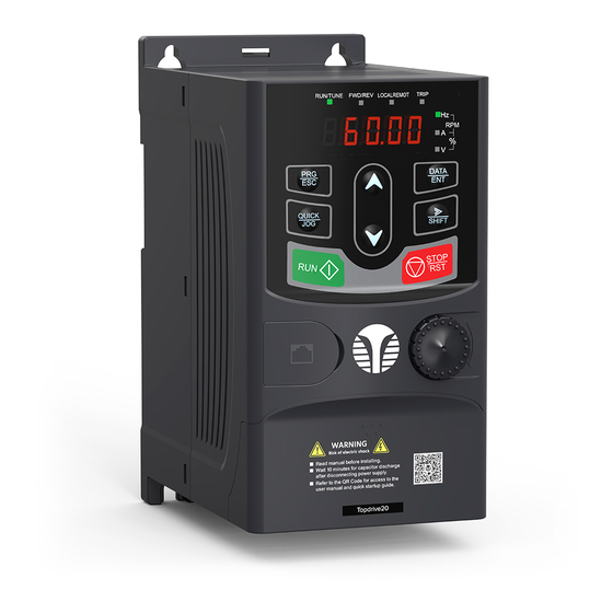
4 Keypad Operation Procedure 4.1 Keypad introduction The keypad is used to control TD20 series VFDs, read the state data and adjust parameters. Figure 4-1 Keypad Note: The external keypads are optional (including the external keypads with and without the function of parameter copying). - Page 21 TD20 Series VFD Keypad Operation Procedure Serial Name Description LED on when the VFD is in the fault state; LED off in normal state; LED blinking means the VFD is in the pre-alarm state. Mean the unit displayed currently Frequency unit...
-
Page 22: Keypad Displaying
AI1 to 0V/0mA before starting the VFD. 4.2 Keypad displaying The keypad displaying state of TD20 series VFDs is divided into stopping state parameter, running state parameter, function code parameter editing state and fault alarm state and so on. -
Page 23: Keypad Operation
TD20 Series VFD Keypad Operation Procedure 4.1.2 Displayed state of running parameters After the VFD receives valid running commands, the VFD will enter into the running state and the keypad will display the running parameters. RUN/TUNE LED on the keypad is on, while the FWD/REV is determined by the current running direction which is shown as figure 4-2. - Page 24 4.3.2 How to set the password of the VFD TD20 series VFDs provide password protection function to users. Set P7.00 to gain the password and the password protection becomes valid instantly after quitting from the function code editing state. Press PRG/ESC again to the function code editing state, "0.0.0.0.0"...
- Page 25 TD20 Series VFD Keypad Operation Procedure 4.3.3 How to watch the VFD state through function codes TD20 series VFDs provide group P17 as the state inspection group. Users can enter into P17 directly to watch the state. All digits are blinking.
-
Page 26: Function Parameters
Function Parameters 5 Function Parameters The function parameters of TD20 series VFDs have been divided into 30 groups (P00–P29) according to the function, of which P18–P28 are reserved. Each function group contains certain function codes applying 3-level menus. For example, "P08.08" means the eighth function code in the P8 group function, P29 group is factory reserved, and users are forbidden to access these parameters. - Page 27 TD20 Series VFD Function Parameters Function Default Name Detailed instruction of parameters Modify code value ("LOCAL/REMOT" light off) Carry out the command control by RUN, STOP/RST on the keypad. Set the multi-function key QUICK/JOG to FWD/REVC shifting function (P07.02=3) to change the running direction;...
- Page 28 (function code P00.03) 4: High-speed pulse HDI setting The frequency is set by high-speed pulse terminals. TD20 series VFDs provide 1 high speed pulse input as the standard configuration. The pulse frequency range is 0.00–50.00kHz. 100.0% of the high speed pulse input setting corresponds to the maximum frequency in forward direction (function code P00.03) and -100.0%...
- Page 29 TD20 Series VFD Function Parameters Function Default Name Detailed instruction of parameters Modify code value The VFD runs at multi-step speed mode when P00.06=6 or P00.07=6. Set P05 to select the current running step, and set P10 to select the current running frequency.
- Page 30 DEC time means the time needed if the VFD speeds model down from the Max. Output frequency to 0Hz (P00.03). TD20 series VFDs have four groups of ACC/DEC time Depend ○ which can be selected by P05. The factory default P00.12...
- Page 31 TD20 Series VFD Function Parameters Function Default Name Detailed instruction of parameters Modify code value Factory setting of carrier Motor type frequency 0.4–2.2kW 8kHz The advantage of high carrier frequency: ideal current waveform, little current harmonic wave and motor noise.
- Page 32 TD20 Series VFD Function Parameters Function Default Name Detailed instruction of parameters Modify code value 0: No operation 1: Restore the default value Function 2: Clear fault records ◎ P00.18 restore Note: The function code will restore to 0 after finishing parameter the operation of the selected function code.
- Page 33 TD20 Series VFD Function Parameters Function Default Name Detailed instruction of parameters Modify code value Setting range: 0.0–50.0s The braking The VFD will carry out DC braking at the braking current ◎ P01.03 current before set before starting and it will speed up after the DC 0.0%...
- Page 34 TD20 Series VFD Function Parameters Function Default Name Detailed instruction of parameters Modify code value decreases to 0Hz, the VFD stops. 1: Coast to stop: after the stop command becomes valid, the VFD ceases the output immediately. And the load coasts to stop at the mechanical inertia.
- Page 35 TD20 Series VFD Function Parameters Function Default Name Detailed instruction of parameters Modify code value Set the threshold point of the VFD: Switching 0: Switch after zero frequency between ◎ P01.14 1: Switch after the starting frequency FWD/REV 2: Switch after the speed reach P01.15 and delay for rotation P01.24...
- Page 36 TD20 Series VFD Function Parameters Function Default Name Detailed instruction of parameters Modify code value lower limit one 0: Run at the lower-limit frequency (valid if the 1: Stop lower limit 2: Hibernation frequency is The VFD will coast to stop when the set frequency is above 0) lower than the lower-limit one.if the set frequency is...
- Page 37 TD20 Series VFD Function Parameters Function Default Name Detailed instruction of parameters Modify code value The function determines the brake release after the Start delay running command is given, and the VFD is in a stand-by ○ P01.23 0.0s time state and wait for the delay time set by P01.23...
- Page 38 TD20 Series VFD Function Parameters Function Default Name Detailed instruction of parameters Modify code value Stator resistor Depend ○ P02.06 0.001–65.535Ω asynchronous model motor Rotor resistor Depend ○ P02.07 0.001–65.535Ω asynchronous model motor Leakage Depend inductance of ○ P02.08 0.1–6553.5mH...
- Page 39 TD20 Series VFD Function Parameters Function Default Name Detailed instruction of parameters Modify code value for the iron core of AM1 0: No protection 1: Common motor (with low speed compensation). Because the heat-releasing effect of the common motors will be weakened, the corresponding electric heat protection will be adjusted properly.
- Page 40 TD20 Series VFD Function Parameters Function Default Name Detailed instruction of parameters Modify code value P03 Group Vector control Speed loop The parameters P03.00–P03.05 only apply to vector ○ 20.0 P03.00 proportional control mode. Below the switching frequency 1 (P03.02), gain1 the speed loop PI parameters are: P03.00 and P03.01.
- Page 41 TD20 Series VFD Function Parameters Function Default Name Detailed instruction of parameters Modify code value coefficient I value; Only apply to the vector control mode without PG 0 (P00.00=0). Setting range: 0–65535 This parameter is used to enable the torque control mode, and set the torque setting means.
- Page 42 TD20 Series VFD Function Parameters Function Default Name Detailed instruction of parameters Modify code value defined value Torque control reverse rotation 60.00 ○ P03.17 upper-limit frequency keypad defined value Upper-limit This function code is used to select the electromotion setting of and braking torque upper-limit setting source selection.
- Page 43 TD20 Series VFD Function Parameters Function Default Name Detailed instruction of parameters Modify code value limit dependent on the site situation. Setting range: 0.0–120.0% Pre-activate the motor when the VFD starts up. Build up Pre-exciting a magnetic field inside the VFD to improve the torque ○...
- Page 44 TD20 Series VFD Function Parameters Function Default Name Detailed instruction of parameters Modify code value frequency torque. P04.01 is for the Max. output voltage P04.02 defines the percentage of closing frequency of manual torque to f Torque boost should be selected according to the load.
- Page 45 TD20 Series VFD Function Parameters Function Default Name Detailed instruction of parameters Modify code value voltage point 3 0.0%–110.0% (rated motor voltage) Setting range of P04.05: P04.03– P04.07 Setting range of P04.07: P04.05–P02.02 (rated motor voltage frequency) This function code is used to compensate the change of the rotation speed caused by load during compensation SVPWM control to improve the rigidity of the motor.
- Page 46 TD20 Series VFD Function Parameters Function Default Name Detailed instruction of parameters Modify code value 6: PID setting voltage; 7: MODBUS communication setting voltage; 8–10: Reversed Note: 100% corresponds to the rated voltage of the motor. The function code is the voltage digital set value when Keypad the voltage setting channel is selected as "keypad...
- Page 47 TD20 Series VFD Function Parameters Function Default Name Detailed instruction of parameters Modify code value P05 Group Input terminals HDI input 0: HDI is high pulse input. See P05.49–P05.54 ◎ P05.00 selection 1: HDI is switch input Note: S1–S4, HDI are the upper terminals on the control S1 terminals board and P05.12 can be used to set the function of...
- Page 48 TD20 Series VFD Function Parameters Function Default Name Detailed instruction of parameters Modify code value 33: Cancel the frequency change setting temporarily 34: DC brake 35: Reserve 36: Shift the command to the keypad 37: Shift the command to the terminals...
- Page 49 TD20 Series VFD Function Parameters Function Default Name Detailed instruction of parameters Modify code value direction by the defined FWD and REV terminals command. Running command Stopping Forward running Reverse running Hold on 1: 2-wire control 2; Separate the enable from the direction.
- Page 50 TD20 Series VFD Function Parameters Function Default Name Detailed instruction of parameters Modify code value 3: 3-wire control 2; Sin is the enabling terminal on this mode, and the running command is caused by SB1 or SB3 and both of them control the running direction.NC SB2 generates the stop command.
- Page 51 TD20 Series VFD Function Parameters Function Default Name Detailed instruction of parameters Modify code value switching off delay time S3 terminal ○ 0.000s P05.18 switching on delay time terminal ○ 0.000s P05.19 switching off delay time S4 terminal ○ 0.000s P05.20...
- Page 52 TD20 Series VFD Function Parameters Function Default Name Detailed instruction of parameters Modify code value Corresponding Lower limit of ○ setting 0.00V P05.37 100% Correspondin g setting of the ○ 0.0% P05.38 -10V lower limit of 20mA AI1/AI2 Upper limit of ○...
- Page 53 TD20 Series VFD Function Parameters Function Default Name Detailed instruction of parameters Modify code value HDI low frequency setting Upper limit 50.000 ○ P05.52 frequency of P05.50–50.000kHz Correspondin g setting of ○ 100.0% P05.53 upper limit -100.0%–100.0% frequency of HDI frequency ○...
- Page 54 TD20 Series VFD Function Parameters Function Default Name Detailed instruction of parameters Modify code value 26: Establishment of DC bus voltage 27–30: Reserved The function code is used to set the pole of the output terminal. Polarity When the current bit is set to 0, input terminal is positive.
- Page 55 TD20 Series VFD Function Parameters Function Default Name Detailed instruction of parameters Modify code value 8: Set torque value (relative to 2 times the rated torque of the motor) 9: Output torque (relative to 2 times the rated torque of...
- Page 56 TD20 Series VFD Function Parameters Function Default Name Detailed instruction of parameters Modify code value g AO2 output Setting range of P06.24: P06.22–100.0% to the upper Setting range of P06.25: 0.00V–10.00V limit Setting range of P06.26: 0.000s–10.000s AO2 output ○...
- Page 57 TD20 Series VFD Function Parameters Function Default Name Detailed instruction of parameters Modify code value selection 1: Jogging 2: Switch display state via shift key 3: Switch between FWD/REV rotation 4: Clear UP/DOWN setting 5: Coast to stop 6: Switch running command ref. mode in order...
- Page 58 TD20 Series VFD Function Parameters Function Default Name Detailed instruction of parameters Modify code value BIT13: pulse counter value BIT14: reserved BIT15: PLC and the current step of multi-step speed 0x0000–0xFFFF BIT0: analog AI1 value (V on) BIT1: analog AI2 value (V on)
- Page 59 TD20 Series VFD Function Parameters Function Default Name Detailed instruction of parameters Modify code value Rectifier ● P07.11 bridge module -20.0–120.0° C temperature Convertering ● P07.12 module -20.0–120.0° C temperature Software ● P07.13 1.00–655.35 version Local ● P07.14 accumulative 0–65535h...
- Page 60 TD20 Series VFD Function Parameters Function Default Name Detailed instruction of parameters Modify code value Factory bar ● P07.23 0x0000–0xFFFF code 3 Factory bar ● P07.24 0x0000–0xFFFF code 4 Factory bar ● P07.25 0x0000–0xFFFF code 5 Factory bar ● P07.26 0x0000–0xFFFF...
- Page 61 TD20 Series VFD Function Parameters Function Default Name Detailed instruction of parameters Modify code value Current fault ● 0.00Hz P07.33 running frequency Ramp reference 0.00Hz P07.34 frequency at current fault Output voltage P07.35 at the current fault Output current 0.0A P07.36...
- Page 62 TD20 Series VFD Function Parameters Function Default Name Detailed instruction of parameters Modify code value current at previous fault Bus voltage at ● 0.0V P07.45 previous fault The Max. ● 0.0° C P07.46 temperature at previous fault Input terminals ●...
- Page 63 Refer to P00.11 and P00.12 for detailed definition. ○ P08.02 ACC time 3 TD20 series define four groups of ACC/DEC time which model can be selected by P5 group. The first group of Depend ACC/DEC time is the factory default one.
- Page 64 TD20 Series VFD Function Parameters Function Default Name Detailed instruction of parameters Modify code value range 1 setting the jumping frequency. The VFD can set three jumping frequency. But this function will be invalid if all Jumping ○ jumping points are 0.
- Page 65 TD20 Series VFD Function Parameters Function Default Name Detailed instruction of parameters Modify code value from the highest point to the lowest one. Setting range of P08.15: 0.0–100.0% (relative to the set frequency) Setting range of P08.16: 0.0–50.0% (relative to the traverse range) Setting range of P08.17: 0.1–3600.0s...
- Page 66 TD20 Series VFD Function Parameters Function Default Name Detailed instruction of parameters Modify code value Frequency The output frequency of the VFD changes as the load. decreasing And it is mainly used to balance the power when several ○ 0.00Hz P08.30...
- Page 67 TD20 Series VFD Function Parameters Function Default Name Detailed instruction of parameters Modify code value This parameter is used to control the internal braking Energy unit. ○ P08.37 Braking 0: Disabled enable 1: Enabled Note: Only applied to internal braking unit.
- Page 68 TD20 Series VFD Function Parameters Function Default Name Detailed instruction of parameters Modify code value 3: Neither ∧/∨ keys nor digital potentiometer adjustments are valid LED tens: frequency control selection 0: Only valid when P00.06=0 or P00.07=0 1: Valid for all frequency setting manner...
- Page 69 TD20 Series VFD Function Parameters Function Default Name Detailed instruction of parameters Modify code value changing ratio 0x000–0x111 LED ones: Action selection when power off. 0: Save when power off 1: Clear when power off LED tens: Action selection when MODBUS set...
- Page 70 TD20 Series VFD Function Parameters Function Default Name Detailed instruction of parameters Modify code value The cooling is better. The current of the stator other than the rotor increases during magnetic flux braking, while the cooling of the stator is more effective than the rotor.
- Page 71 TD20 Series VFD Function Parameters Function Default Name Detailed instruction of parameters Modify code value 5–7: Reserved Note: The reference channel and the feedback channel can not coincide, otherwise, PID can not control effectively. 0: PID output is positive: when the feedback signal exceeds the PID reference value, the output frequency of the VFD will decrease to balance the PID.
- Page 72 TD20 Series VFD Function Parameters Function Default Name Detailed instruction of parameters Modify code value This parameter means the sampling cycle of the feedback. The modulator calculates in each sampling Sampling ○ P09.07 cycle. The longer the sapling cycle is, the slower the 0.100s...
- Page 73 TD20 Series VFD Function Parameters Function Default Name Detailed instruction of parameters Modify code value Setting range of P09.12: 0.0–3600.0s 0x00–0x11 LED ones: 0: Keep on integral adjustment when the frequency achieves the upper and low limit; the integration shows the change between the reference and the feedback unless it reaches the internal integral limit.
- Page 74 --f and it 0.0% P10.10 speed 4 can be The running TD20 series VFDs can set 16 stages speed, selected by ○ 0.0s P10.11 time of stage 4 the combination of multi-step terminals 1–4, Multi-step corresponding to the speed 0 to speed 15.
- Page 75 TD20 Series VFD Function Parameters Function Default Name Detailed instruction of parameters Modify code value Output frequency Multi-step ○ 0.0% P10.14 speed 6 The running ○ 0.0s P10.15 time of stage 6 Multi-step ○ 0.0% P10.16 speed 7 The running Terminal 1 ○...
- Page 76 TD20 Series VFD Function Parameters Function Default Name Detailed instruction of parameters Modify code value The running Setting range of P10.(2n+1, 1<n<17): 0.0–6553.5s (min) ○ 0.0s P10.31 time of stage Multi-step ○ 0.0% P10.32 speed 15 The running ○ 0.0s P10.33...
- Page 77 TD20 Series VFD Function Parameters Function Default Name Detailed instruction of parameters Modify code value After the users select the corresponding ACC/DEC time, the combining 16 binary bit will change into decimal bit, and then set the corresponding function codes.
- Page 78 TD20 Series VFD Function Parameters Function Default Name Detailed instruction of parameters Modify code value point at sudden power loss Note: 1. Adjust the parameter properly to avoid the stopping caused by VFD protection during the switching of the grid.
- Page 79 TD20 Series VFD Function Parameters Function Default Name Detailed instruction of parameters Modify code value 0: current limit invalid 1: current limit valid 2: current limit is invalid during constant speed Setting range of P11.05: 0x00–0x12 Setting range of P11.06: 50.0–200.0% Setting range of P11.07: 0.00–50.00Hz/s...
- Page 80 TD20 Series VFD Function Parameters Function Default Name Detailed instruction of parameters Modify code value Detection level of the ○ P11.11 If the VFD current or the output current is lower than underload P11.11, and its lasting time is beyond P11.12, the VFD pre-alarm will output underload pre-alarm.
- Page 81 TD20 Series VFD Function Parameters Function Default Name Detailed instruction of parameters Modify code value short circuit After the VFD stops, when the operation frequency is less than P01.09, set P13.15 to non-zero value and Braking begin stopping short-circuit braking and then DC retention braking.
- Page 82 TD20 Series VFD Function Parameters Function Default Name Detailed instruction of parameters Modify code value applied. 0: No check (N,8,1) for RTU 1: Even check (E,8,1) for RTU 2: Odd check (O,8,1) for RTU 3: No check (N,8,2) for RTU...
- Page 83 TD20 Series VFD Function Parameters Function Default Name Detailed instruction of parameters Modify code value 3: No alarm and stop according to the stop means (under all control modes) 0x00–0x11 LED ones: 0: Write with response: the VFD will respond to all reading and writing commands of the upper monitor.
- Page 84 TD20 Series VFD Function Parameters Function Default Name Detailed instruction of parameters Modify code value Setting range: -300.0%–300.0% (the rated current of the motor) Display the current output torque of the VFD. ● Output torque P17.09 Range: -250.0–250.0% The motor Evaluate the motor rotor frequency on open loop vector ●...
- Page 85 TD20 Series VFD Function Parameters Function Default Name Detailed instruction of parameters Modify code value Display HDI input frequency HDI input ● P17.22 frequency Range: 0.00–50.00kHz Display PID reference value PID reference ● P17.23 value Range: -100.0–100.0% Display PID feedback value PID feedback ●...
- Page 86 TD20 Series VFD Function Parameters Function Default Name Detailed instruction of parameters Modify code value Display the input current in AC side. AC input ● P17.35 current Range: 0.0–5000.0A Display the output torque. Positive value is in the electromotion state, and negative value is in the power ●...
-
Page 87: Fault Tracking
TD20 Series VFD Fault Tracking 6 Fault Tracking 6.1 Maintenance intervals If installed in an appropriate environment, the VFD requires very little maintenance. The table lists the routine maintenance intervals recommended by TECHTOP CANADA INC.. Checking part Checking item Checking method Criterion... - Page 88 TD20 Series VFD Fault Tracking Checking part Checking item Checking method Criterion Ensure that there are no crackles or color-changing of the protective Visual examination layers. Terminals Ensure that there is no damage Visual examination seat Ensure that there is no weeping,...
- Page 89 Fan failure can be predicted by the increasing noise from the fan bearings. If the VFD is operated in a critical part of a process, fan replacement is recommended once these symptoms appear. Replacement fans are available from TECHTOP CANADA INC.. •...
-
Page 90: Fault Solution
Fault is indicated by LEDs. See Operation Procedure. When TRIP light is on, an alarm or fault message on the panel display indicates abnormal VFD state. Using the information given in this chapter, most alarm and fault cause can be identified and corrected. If not, contact with the TECHTOP CANADA INC. office. - Page 91 TD20 Series VFD Fault Tracking 6.2.2 How to reset The VFD can be reset by pressing the keypad key STOP/RST, through digital input, or by switching the power light. When the fault has been removed, the motor can be restarted.
- Page 92 TD20 Series VFD Fault Tracking Fault code Fault type Possible cause Solutions running components. 3. Install the braking components. 4. Check the setting of relative function codes. 1. The voltage of the power 1. Check the input power of DC bus supply is too low.
- Page 93 TD20 Series VFD Fault Tracking Fault code Fault type Possible cause Solutions serious asymmetrical three distribution phase of the load) 2. Check the motor and cable 1. Refer to the overcurrent solution 2. Redistribute Rectify overheat dredge the wind channel or 1.
- Page 94 TD20 Series VFD Fault Tracking Fault code Fault type Possible cause Solutions abnormal. 1. The motor capacity does 1. Change the VFD mode not comply with the VFD 2. Set the rated parameter capability according to the motor 2. The rated parameter of the nameplate motor does not set correctly.
- Page 95 TD20 Series VFD Fault Tracking Fault code Fault type Possible cause Solutions not right. not. 3. The VFD is not connected 3. Increase the maladjustment to the motor. detection time. The actual running time of the Time reach of factory...
- Page 96 TD20 Series VFD Fault Tracking Fault code Fault type Possible cause Solutions 2. There is fault in the current 2. Change the hoare detection circuit 3. Change the main control Grounding shortcut 3. There is a great difference panel ETH2...
-
Page 97: Communication Protocol
TD20 Series VFD Communication Protocol 7 Communication Protocol 7.1 Brief instruction to Modbus protocol Modbus protocol is a software protocol and common language which is applied in the electrical controller. With this protocol, the controller can communicate with other devices via network (the channel of signal transmission or the physical layer, such as RS485). - Page 98 TD20 Series VFD Communication Protocol distance is as below: Baud Max.transmissio Baud Max.transmissio Baud Max.transmissio Baud Max.transmissio rate n distance rate n distance rate n distance rate n distance 1920 2400 4800 9600 1800m 1200m 800m 600m It is recommended to use shield cables and make the shield layer as the grounding wires during RS485 remote communication.
- Page 99 TD20 Series VFD Communication Protocol Twisted pair cables with shield screen Ω 485 + 485 + 485 + Terminal resistor 485 - 485 - 485 - Earth Earth Earth RS232-485 Converter RSM15m Computer Address n Address 1 Address 2 Figure 2 Chrysanthemum connection applications Figure 3 is the star connection.
- Page 100 TD20 Series VFD Communication Protocol 10-bit character frame (BIT1–BIT7 are the digital bits) Check Start bit BIT1 BIT2 BIT3 BIT4 BIT5 BIT6 BIT7 End bit In one character frame, the digital bit takes effect. The start bit, check bit and end bit is used to send the digital bit right to the other device.
- Page 101 TD20 Series VFD Communication Protocol data checkout of the frame (CRC check). Bit checkout of the byte The user can select different bit checkouts or non-checkout, which impacts the check bit setting of each byte. The definition of even checkout: add an even check bit before the data transmission to illustrate the number of "1"...
-
Page 102: Rtu Command Code And Communication Data Illustration
TD20 Series VFD Communication Protocol In ladder logic, CKSM calculated the CRC value according to the frame with the table inquiry. The method is advanced with easy program and quick calculation speed. But the ROM space the program occupied is huge. So use it with caution according to the program required space. - Page 103 TD20 Series VFD Communication Protocol START T1-T2-T3-T4 ADDR Byte number Data high bit of address 0004H Data low bit of address 0004H Data high bit of address 0005H Data low bit of address 0005H CRC CHK low bit CRC CHK high bit...
- Page 104 TD20 Series VFD Communication Protocol CRC CHK high bit T1-T2-T3-T4 RTU slave response message (from the VFD to the master) START T1-T2-T3-T4 ADDR High bit of writing data address Low bit of writing data address High bit of data content...
- Page 105 TD20 Series VFD Communication Protocol Low bit of data content CRC CHK low bit CRC CHK high bit T1-T2-T3-T4 7.3.4 Command code: 10H, continuous writing Command code 10H means that if the master writes data to the VFD, the data number depends on the "data number"...
- Page 106 TD20 Series VFD Communication Protocol the state information and relative function parameters of the VFD. 7.3.5.1 The rules of parameter address of the function codes The parameter address occupies 2 bytes with the high bit in the front and the low bit in the rear. The range of high and low byte are: high byte—00–ffH;...
- Page 107 TD20 Series VFD Communication Protocol Function Address Data meaning instruction instruction definition characteristics 0007H: fault reset 0008H: jogging stop Communication setting frequency 2001H (0–Fmax(unit: 0.01Hz)) PID reference, range (0–1000, 1000 2002H corresponds to 100.0% ) PID feedback, range (0–1000, 1000 2003H corresponds to 100.0% )
- Page 108 TD20 Series VFD Communication Protocol Function Address Data meaning instruction instruction definition characteristics (0–1000, 1000 corresponds to the 100.0% of the rated voltage of the motor) AO output setting 1 200DH (-1000–1000, 1000 corresponds to 100.0%) AO output setting 2 200EH (-1000–1000, 1000 corresponds to 100.0%)
- Page 109 TD20 Series VFD Communication Protocol Function Address Data meaning instruction instruction definition characteristics AI 1 300CH AI 2 300DH Reserved 300EH Reserved 300FH Reserved 3010H Reserved 3011H Reserved 3012H Reserved 3013H External counting 3014H value Torque setting 3015H VFD code...
- Page 110 TD20 Series VFD Communication Protocol Function Default Name Detailed instruction of parameters Modify code value Hibernation restore Setting range: 0.0–3600.0s (valid when P01.20 ○ 0.0s delay time P01.19=2) 0: Disabled ○ P01.21 Restart after power off 1: Enabled, If there is one figure behind the radix point in the setting range or the default value, then the fieldbus ratio value is 10.
- Page 111 TD20 Series VFD Communication Protocol Code Name Meaning exceed the range, but indicate the message frame is an illegal frame. The parameter setting in parameter writing is invalid. For example, Operation failed the function input terminal cannot be set repeatedly.
- Page 112 TD20 Series VFD Communication Protocol beyond the range, the VFD will return fault response message as below: Abnormal Fault code CRC check address response code Abnormal response code 86H means the abnormal response to writing command 06H; the fault code is 04H.
- Page 113 TD20 Series VFD Communication Protocol Function Address Data meaning instruction instruction definition characteristics 0001H: forward running 0002H: reverse running 0003H: forward jogging 0004H: reverse jogging Communication 2000H control command 0005H: stop 0006H: coast to stop (emergency stop) 0007H: fault reset...
- Page 114 DEC time means the time needed if the VFD speeds model down from the Max. Output frequency to 0Hz (P00.03). TD20 series VFDs have four groups of ACC/DEC time Depend ○ which can be selected by P05. The factory default P00.12...
- Page 115 TD20 Series VFD Communication Protocol Continuous Parameters Byte Data CRC check writing address address number number command If the response message is as below: Continuous Parameters Data CRC check writing address address number command Note: The space between above commands is for instruction and there is no space between the commands during actual applications.
-
Page 116: Appendix A Technical Data
TD20 Series VFD Appendix A Technical Data Appendix A Technical Data A.1 Ratings A.1.1 Capacity VFD sizing is based on the rated motor current and power. To achieve the rated motor power given in the table, the rated current of the VFD must be higher than or equal to the rated motor current. Also the rated power of the VFD must be higher than or equal to the rated motor power. -
Page 117: Marking
TD20 Series VFD Appendix A Technical Data Derating coefficient (%) Altitude (m) 1000 2000 3000 4000 A.2 Marking A.2.1 CE marking The CE mark is attached to the VFD to verify that the VFD follows the provisions of the European Low... - Page 118 TD20 Series VFD Appendix A Technical Data 1. The optional EMC filter is selected according to the options and installed as specified in the EMC filter manual. 2. The motor and control cables are selected as specified in this manual.
-
Page 119: Appendix B Dimension Drawings
TD20 Series VFD Appendix B Dimension Drawings Appendix B Dimension Drawings Dimension drawings of the TD20 are shown below. The dimensions are given in millimeters and inches. B.1 External keypad (optional) structure Outline dimensions of the keypad 42.0 17.1 19.0 48.1 19.0... -
Page 120: Vfd Chart
TD20 Series VFD Appendix B Dimension Drawings B.2 VFD chart Wall mounting (unit: mm) Installation Model hole (d) TD20-0R4G-S1 80.0 60.0 160.0 150.0 123.5 120.3 TD20-0R7G-S1 80.0 60.0 160.0 150.0 123.5 120.3 TD20-1R1G-S1 80.0 60.0 160.0 150.0 123.5 120.3 TD20-0R4G-S2 80.0... - Page 121 TD20 Series VFD Appendix B Dimension Drawings Rail mounting (unit: mm) Installation Model hole (d) TD20-0R4G-S1 80.0 160.0 35.4 36.6 123.5 120.3 TD20-0R7G-S1 80.0 160.0 35.4 36.6 123.5 120.3 TD20-1R1G-S1 80.0 160.0 35.4 36.6 123.5 120.3 TD20-0R4G-S2 80.0 160.0 35.4 36.6...
-
Page 122: Appendix C Peripheral Options And Parts
TD20 Series VFD Appendix C Peripheral Options and Parts Appendix C Peripheral Options and Parts This chapter describes how to select the options and parts of TD20 series. C.1 Peripheral wiring Below is the peripheral wiring of TD20 series VFDs. -
Page 123: Power Supply
TD20 Series VFD Appendix C Peripheral Options and Parts Pictures Name Descriptions Prevent from electric shock and protect the power supply and the cables system from overcurrent when short circuits occur. (Please Breaker select the breaker with the function of... - Page 124 TD20 Series VFD Appendix C Peripheral Options and Parts Required Wire Wire Model Terminal Type Torque Connector Range (in-lbs) (##) TD20-0R4G-S1 Input and Output 4.4 or 8.8 TD20-0R7G-S1 14 AWG Optional Terminal TD20-1R1G-S1 TD20-0R4G-S2 Input and Output 4.4 or 8.8...
-
Page 125: Fuse
TD20 Series VFD Appendix C Peripheral Options and Parts Model Required Torque (in-lbs) Wire Range (AWG) TD20-0R7G-2 TD20-0R7G-4 TD20-1R5G-4 TD20-2R2G-4 C.3.2 Control cables All analog control cables and the cable used for the frequency input must be shielded. The relay cable needs the cable type with braided metallic screen. -
Page 126: Reactors
C.6 Filters C.6.1 C3 Filter type instruction C3 filers are optional for TD20 series VFDs. The input interference filter can decrease the interference of the VFD to the surrounding equipments. Output interference filter can decrease the radio noise cause by the cables between the VFD and the motor and the leakage current of the conducting wires. -
Page 127: Braking Components
TD20 Series VFD Appendix C Peripheral Options and Parts C.6.2 Installation instruction for C3 filter The installation procedures for C3 filter are as below: 1. Connect the filter cable to the corresponding input terminal of the VFD according to the label;... - Page 128 TD20 Series VFD Appendix C Peripheral Options and Parts TD20 series VFDs have internal braking units. Brake The consumed power of the brake resistor at resistor Min. Type of 100% of brake Model brake unit resistor 10% braking 50% braking 80% braking braking (Ω)
- Page 129 TD20 Series VFD Appendix C Peripheral Options and Parts TD20 External brake resistor -127-...
-
Page 130: Appendix D Further Information
D.1 Product and service inquiries Address any inquiries about the product to your local TECHTOP offices, quoting the type designation and serial number of the unit in question. A listing of TECHTOP sales, support and service contacts can be found by navigating to www.techtopcanada.com.
Need help?
Do you have a question about the TD20 Series and is the answer not in the manual?
Questions and answers
How do you get this invertor to operate at a remote location ?
To operate the TECHTOP TD20 Series inverter at a remote location, use an external keypad with parameter copy functionality. Connect the external keypad to the VFD and configure AI1 settings. Ensure that the external keypad AI1 is set correctly and adjust the local potentiometer AI1 to 0V/0mA before starting the VFD if the external keypad AI1 is the frequency reference source. The keypad will display different states, including stopping, running, function code editing, and fault alarm.
This answer is automatically generated