Table of Contents
Advertisement
Advertisement
Chapters
Table of Contents

Related Manuals for AutomationDirect DURAPULSE Series


Summary of Contents for AutomationDirect DURAPULSE Series
- Page 1 AC Drive User Manual 230V Class: 1 - 50 Hp 460V Class: 1 - 100 Hp...
-
Page 3: Trademarks
This publication is based on information that was available at the time it was printed. At AutomationDirect we constantly strive to improve our products and services, so we reserve the right to make changes to the products and/or publications at any time without notice and without any obligation. -
Page 4: Avertissement
Nulle partie de ce manuel ne doit être copiée, reproduite ou transmise de quelque façon que ce soit sans le consentement préalable écrit de la société Automationdirect.com® Incorporated. AutomationDirect conserve les droits exclusifs à l'égard de tous les renseignements contenus dans le présent document. - Page 5 WARNING : Read this manual thoroughly before using DURA Series AC Motor Drives. ARNING PULSE : AC input power must be disconnected before performing any maintenance. ARNING Do not connect or disconnect wires or connectors while power is applied to the circuit.
- Page 6 w–4 DURA PULSE AC Drive User Manual 1st Ed. Rev. D 05/2013...
-
Page 7: Dura Pulse
DURA AC D PULSE RIVE ANUAL EVISION ISTORY Please include the Manual Number and the Manual Issue, both shown below, when communicating with Technical Support regarding this publication. Manual Number: GS3-M Issue: First Edition, Revision D Issue Date: 05/2013 Publication History Issue Date Description of Changes... - Page 8 Revision History BLANK PAGE h–2 DURA AC Drive User Manual PULSE...
-
Page 9: Table Of Contents
ABLE OF ONTENTS WARNINGS ........w–1 Trademarks ........w–1 AVERTISSEMENT . - Page 10 Table of Contents Chapter 2: Installation and Wiring ....2–1 Ambient Conditions ....... .2–2 Storage Conditions .
- Page 11 Table of Contents Chapter 4: AC Drive Parameters ....4–1 DURA Parameter Summary ......4–2 PULSE Parameters available only in later firmware versions of DURA...
- Page 12 PULSE Communicating with AutomationDirect PLCs ... .5–14 Step 1: Choose the Appropriate CPU ..... .5–14 Step 2: Make the Connections .
- Page 13 Table of Contents Chapter 6: Maintenance and Troubleshooting ..6–1 Maintenance and Inspection ......6–2 Monthly Inspection .
- Page 14 PULSE with AutomationDirect PLCs ..... . .B–1 Compatible AutomationDirect PLCs and Modules ..B–2 Typical PLC Connections to DURA AC Drives .
- Page 15 HAPTER HAPTER HAPTER ETTING TARTED Contents of this Chapter... Manual Overview ....... .1–2 Overview of this Publication .
-
Page 16: Chapter 1: Getting Started
By Telephone: 770-844-4200 (Mon.-Fri., 9:00 a.m.-6:00 p.m. E.T.) On the Web: www.automationdirect.com Our technical support group is glad to work with you in answering your questions. If you cannot find the solution to your particular application, or, if for any reason you need additional technical assistance, please call technical support at 770-844-4200. -
Page 17: Dura Pulse Ac Drive Introduction
Chapter 1: Getting Started DURA AC Drive Introduction PULSE Purpose of AC Drives AC drives are generally known by many different names: Adjustable Frequency Drives (AFD), Variable Frequency Drives (VFD), and Inverters. Drives are used primarily to vary the speed of three phase AC induction motors, and they also provide non-emergency start and stop control, acceleration and deceleration, and overload protection. - Page 18 Chapter 1: Getting Started Selecting the Proper Drive Rating (continued) E. Calculate required output amperage Use the chart below to calculate the required FLA of the AC drive, as shown by the following examples. Select the rating that equals the motor’s voltage and equals or exceeds the calculated amperage.
-
Page 19: Model Number Explanation
IND. CONT. EQ |GS3-2020+T331001:~ Barcode GS3-2020+T331001 Serial Number Automationdirect.com, Inc. Drive Package Contents After receiving the AC motor drive, please check for the following: • Make sure that the package includes an AC drive, the DURA PULSE AC Drive User Manual, and the DURA AC Drive Quick Reference. -
Page 20: External Parts And Labels
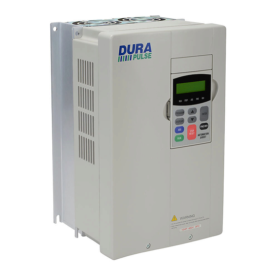
Chapter 1: Getting Started External Parts and Labels GS3-25P0 shown Mounting Screw Holes Ventilation Slots Nameplate Label Cover Digital Keypad Heat Sink Fins Input Power Terminals Braking Terminals Control Terminals Output Power Terminals Input Mode Switch (Sink/Source) Serial Communication Port 1–6 DURA PULSE... -
Page 21: Dura Pulse Ac Drive Specifications
Chapter 1: Getting Started DURA AC Drive Specifications PULSE Please review the AutomationDirect Terms and Conditions for this product. There is no 30-day money-back guarantee on any drive over 10 hp. 230V Class Model Name: GS3-xxx 21P0 22P0 23P0 25P0... - Page 22 * All 3-phase power sources must be symmetrical. Do not connect DURApulse drives to grounded, center-tapped delta transformers (which are typically used for lighting circuits). Please review the AutomationDirect Terms and Conditions for this product. There is no 30-day money-back guarantee on any drive over 10 hp.
- Page 23 Chapter 1: Getting Started General Specifications Control Characteristics Pulse Width Modulation, Carrier frequency 1-15 kHz, adjustable, depending on the model. This system determines the control methods Control System of the AC drive. 00: V/Hz open loop control, 01: V/Hz closed loop control, 02: Sensorless Vector 03: Sensorless Vector with external feedback Rated Output Frequency...
- Page 24 Chapter 1: Getting Started General Specifications (cont.) Electronic Thermal, Overload Relay, Auto Restart after Fault, Momentary Power Loss, Reverse Operation Inhibit, Auto Voltage Regulation, Over-Voltage Stall Prevention, Auto Adjustable Protective Functions Accel/Decel, Over-Torque Detection Mode, Over-Torque Detection Level, Over-Torque Detection Time, Over-Current Stall Prevention during Acceleration, Over-Current Stall Prevention during Operation Operator Devices 9-key, 2 line x 16 character LCD display, 5 status LEDs...
- Page 25 HAPTER HAPTER HAPTER NSTALLATION IRING Contents of this Chapter... Ambient Conditions ......2–2 Storage Conditions .
-
Page 26: Chapter 2: Installation And Wiring
Chapter 2: Installation and Wiring Ambient Conditions Ambient environmental conditions for use: Ambient Conditions Ambient Temperature -10°C to 40°C (14°F to 104°F) Relative Humidity 0 to 90% (non-condensing) Atmosphere Pressure 86 kPa to 106 kPa Vibration 9.8 m/s (1G) less than 10 Hz, 5.9 m/s (0.6G) 10 to 60 Hz Altitude 1000m or lower above sea level, keep from corrosive Installation Location... -
Page 27: Installation
Chapter 2: Installation and Wiring Installation Install the AC drive in an enclosure that is specifically designed to house electrical and electronic control equipment. Provide proper spacing within the enclosure to allow the dissipation of heat produced by the drive and any other included electrical and electronic equipment. -
Page 28: Dimensions
Chapter 2: Installation and Wiring Dimensions Frame A Part numbers: GS3-21P0, GS3-22P0, GS3-41P0, GS3-42P0 118.0 [4.65] 160.0 [6.30] 108.0 [4.25] 5.5[0.22] Dia. STOP FWD REV PROGRAM ENTER DISPLAY FWD/REV STOP RESET WARNING Do not connect AC power to output terminals T1,T2 and T3. Risk of electrical shock. - Page 29 Chapter 2: Installation and Wiring Dimensions (continued) Frame A with Fan Part Numbers: GS3-43P0 118.0 [4.65] 145.0 [5.71] 108.0 [4.25] Dia. 5.5[0.22] STOP FWD REV PROGRAM ENTER DISPLAY FWD/REV STOP RESET WARNING Do not connect AC power to output terminals T1,T2 and T3. Risk of electrical shock.
- Page 30 Chapter 2: Installation and Wiring Dimensions (continued) Frame B Part numbers: GS3-23P0, GS3-25P0, GS3-45P0 150.0 [5.91] 135.0 [5.32] 160.2 [6.31] RUN STOP PROGRAM ENTER DISPL FWD/REV STOP RESET WARNING Do not connect AC power to output terminals T1,T2 and T3. Risk of electrical shock.
- Page 31 Chapter 2: Installation and Wiring Dimensions (continued) Frame C Part numbers: GS3-27P5, GS3-2010, GS3-2015 GS3-47P5, GS3-4010, GS3-4015 200.0 [7.88] Dia. 7.0 (0.28) 183.2 [7.22] 185.6 [7.31] STOP PROGRAM ENTER DISPLAY FWD/REV STOP RESET WARNING Do not connect AC power to output terminals T1,T2 and T3. Risk of electrical shock.
- Page 32 Chapter 2: Installation and Wiring Dimensions (continued) Frame D Part numbers: GS3-2020, GS3-2025, GS3-2030 GS3-4020, GS3-4025, GS3-4030 250.0 [9.84] 10.0 [0.39] Dia. 205.4 [8.08] 226.0 [8.90] RUN STOP PROGRAM ENTER DISPLAY FWD/REV STOP RESET WARNING Do not connect AC power to output terminals T1,T2 and T3. Risk of electrical shock.
- Page 33 Chapter 2: Installation and Wiring Dimensions (continued) Frame E Part Numbers: GS3-2040, GS3-2050 GS3-4040, GS3-4050, GS3-4060 Dia. 13.0 (0.51) 370.0 [14.57] 260.0 [10.24] 335.0 [13.19] Dia. 18.0(0.71) STOP JOG FWD PROGRAM ENTER DISPLAY FWD/REV STOP RESET 18.0 [0.71] WARNING 132.5 [5.22] Dia.
- Page 34 Chapter 2: Installation and Wiring Dimensions (continued) Frame F Part Numbers: GS3-4075, GS3-4100 425.0 [16.73] 264.0 [10.39] 385.0 [15.16] 18.0 [0.71] WARNING 130.4 [5.13] 280.0 [11.02] Dia. 22.0(0.87) Dia. 74.8(2.94) R6.5[0.25] 13.0[0.51] Units: mm [inches] 2–10 DURA PULSE AC Drive User Manual 1st Ed.
-
Page 35: Circuit Connections
: Any electrical or mechanical modification to this equipment without prior ARNING written consent of AutomationDirect.com, Inc. will void all warranties, may result in a safety hazard, and may void the UL listing. : Do not connect the AC input power to the T1, T2, and T3 output terminals. - Page 36 T1, T2, and T3 side of AC drive. Do not use a Capacitor, L-C Filter (Inductance-Capacitance), or R-C Filter (Resistance-Capacitance), unless approved by AutomationDirect. 16. When using a GFCI (Ground Fault Circuit Interrupt), select current sensor with sensitivity of 200mA, and not less than 0.1-second detection to avoid nuisance tripping.
-
Page 37: Terminal Wiring Diagrams
Chapter 2: Installation and Wiring Terminal Wiring Diagrams GS3-21P0, GS3-22P0, GS3-41P0, GS3-42P0, GS3-43P0 T1 T2 T3 GS3-23P0, GS3-25P0, GS3-45P0 T1 T2 T3 L1 L2 L3 DURA 2–13 1st Ed. Rev. D 05/2013 PULSE AC Drive User Manual... - Page 38 Chapter 2: Installation and Wiring Terminal Wiring Diagrams (continued) GS3-27P5, GS3-47P5, GS3-2010, GS3-4010, GS3-2015, GS3-4015 POWER MOTOR GS3-2020, GS3-4020, GS3-2025, GS3-4025, GS3-2030, GS3-4030 POWER MOTOR 2–14 DURA PULSE AC Drive User Manual 1st Ed. Rev. D 05/2013...
- Page 39 Chapter 2: Installation and Wiring Terminal Wiring Diagrams (continued) GS3-2040, GS3-2050 POWER MOTOR GS3-4040, GS3-4050,GS3-4060 T1 T2 POWER MOTOR DURA 2–15 1st Ed. Rev. D 05/2013 PULSE AC Drive User Manual...
- Page 40 Chapter 2: Installation and Wiring Terminal Wiring Diagrams (continued) GS3-4075, GS3-4100 POWER MOTOR 2–16 DURA PULSE AC Drive User Manual 1st Ed. Rev. D 05/2013...
-
Page 41: Main Circuit Wiring
Chapter 2: Installation and Wiring Main Circuit Wiring Main Circuit Terminals Terminal Description L1, L2, L3 Input Power T1, T2, T3 AC Drive Output B1, B2 Braking Resistor Connection (Under 20HP) +2, – (negative) External Dynamic Brake Unit (20HP & Over) Ground Main Circuit Wiring Specifications Terminal... -
Page 42: Power Wiring Diagrams
Chapter 2: Installation and Wiring Power Wiring Diagrams Drives under 20hp Users must connect wiring according to the circuit diagram shown below. Braking resistor (optional) JUMPER (–) Power Source AC Motor 200-240V+-10% 3 Ø DURA (50,60Hz+-5%) PULSE GS3-xxxx 380-480V+-10% (50,60Hz+-5%) Use any two of L1, L2, L3 for 230V 1-phase models Note: Grounding terminals... -
Page 43: Power Wiring Diagrams
Chapter 2: Installation and Wiring Power Wiring Diagrams (continued) Drives 40–50hp (230VAC) & 75–100hp (460VAC) Users must connect wiring according to the circuit diagram shown below. Dynamic Brake Unit Braking resistor (optional) (optional) Dynamic Brake Unit Braking resistor (optional) JUMPER (optional) –... -
Page 44: Control Terminal Designations
Chapter 2: Installation and Wiring Control Terminal Designations Control Circuit Terminals Terminal Description Remarks Symbol (+24V, 20mA), used only for AC drive digital inputs wired for +24V DC Voltage Source source mode operation Digital Input 1 Digital Input 2 Digital Input 3 Digital Input 4 Input Voltage: Internally Supplied (see W below) -
Page 45: Control Wiring Diagram - Sinking Inputs
Chapter 2: Installation and Wiring Control Wiring Diagram – Sinking Inputs Users must connect wiring according to the circuit diagram shown below. : Do not plug a modem or telephone into the DURA RJ-12 Serial PULSE ARNING Comm Port, or permanent damage may result. DURA PULSE AC Drive... -
Page 46: Control Wiring Diagram - Sourcing Inputs
Chapter 2: Installation and Wiring Control Wiring Diagram – Sourcing Inputs Users must connect wiring according to the circuit diagram shown below. : Do not plug a modem or telephone into the DURA RJ-12 Serial PULSE ARNING Comm Port, or permanent damage may result. DURA PULSE AC Drive... -
Page 47: External Accessories
Chapter 2: Installation and Wiring External Power Supply Please follow the specific power supply requirements Accessories shown in C HAPTER Fuses Under 20hp Input fuses protect the AC drive from excessive input current due to line surges, short circuits, and ground From power supply faults. - Page 48 Chapter 2: Installation and Wiring External Accessories Power Supply (continued) Please follow the specific power supply requirements shown in C HAPTER Fuse 20hp & Over Input fuses protect the AC drive from excessive input From power supply current due to line surges, short circuits, and ground faults.
- Page 49 HAPTER HAPTER HAPTER EYPAD PERATION UICKSTART Contents of this Chapter... The DURA Digital Keypad ..... . .3–2 PULSE LCD Display ..........3–2 LED Indicators .
-
Page 50: Chapter 3: Keypad Operation And Quickstart
Chapter 3: Keypad Operation and Quickstart The DURA Digital Keypad PULSE The digital keypad includes a 2 line x 16 character LCD display, 5 status LED Indicators, and 9 function keys. The diagram below shows all of the features of the digital keypad and an overview of their functions. -
Page 51: Function Keys
Chapter 3: Keypad Operation and Quickstart Function Keys Program Key Pressing the PROGRAM key will display the parameter groups. Use the UP/DOWN or PROGRAM keys to cycle through the parameter groups. The LCD display will show which parameter group is currently selected. Display Key Pressing the DISPLAY key on the keypad repeatedly will cycle through the status messages on the AC... -
Page 52: Displaying The Status Of The Dura
Chapter 3: Keypad Operation and Quickstart Displaying the Status of the DURA PULSE AC Drive Press the DISPLAY key on the keypad repeatedly to cycle through the status messages on the AC drive. The diagram below shows the order of the status messages as you cycle through them and shows the definition of the status messages. -
Page 53: Pulse Ac Drive
Chapter 3: Keypad Operation and Quickstart Programming the DURA PULSE AC Drive The DURA AC Drive parameters are organized into eleven (11) different groups PULSE according to their functions, plus a special “Copy Keypad” function for storing up to four (4) different sets of program parameters into the keypad. The illustration below shows you how to navigate through the parameter groups and parameter settings. -
Page 54: Dura Pulse Quickstart
Chapter 3: Keypad Operation and Quickstart DURA Quickstart PULSE The following examples will help you quickly set up your DURA AC Drive PULSE for two common applications. The first example applies to an application that requires constant torque, and the second example requires variable torque in its application. - Page 55 Chapter 3: Keypad Operation and Quickstart Parameter Setup In order to meet the needs of this application, the parameters should be set as follows: P0.00 Motor Nameplate Voltage Setting: 460 Range: 230V series: 200/208/220/230/240 Default Setting: 240 460V series: 380/400/415/440/460/480 Default Setting: 480 This parameter setting is determined by the motor nameplate.
- Page 56 Chapter 3: Keypad Operation and Quickstart Acceleration Time Setting: 5.0 P1.01 Range: 0.1 to 600 sec Default Setting: 10 sec The motor should accelerate from 0 RPM to Maximum Motor RPM (P0.04) in 5 seconds. Deceleration Time Setting: 5.0 P1.02 Range: 0.1 to 600 sec Default Setting: 30 sec The motor should decelerate from 2000 rpm;...
- Page 57 Chapter 3: Keypad Operation and Quickstart Source of Frequency Command Setting: 02 P4.00 Default: 01 Settings: Frequency determined by digital keypad up/down 02* Frequency determined by 0 to +10V input on AI1 terminal. Frequency determined by 4 to 20 mA input on AI2 terminal.
-
Page 58: Example 2: Variable Torque (E.g. Fans, Centrifugal Pumps, Etc.)
Chapter 3: Keypad Operation and Quickstart Example 2: Variable torque (e.g. fans, centrifugal pumps, etc.) In this example, the AC drive needs to operate a motor that is connected to a centrifugal pump. As in Example 1, we will make a list of the needs for the application in order to decide which parameters need modifications. - Page 59 Chapter 3: Keypad Operation and Quickstart Motor Base Frequency Setting: 60 P0.02 Range: 50/60/400 Default Setting 60 This parameter setting is determined by the motor nameplate. Motor Base RPM Setting: 3525 P0.03 Range: 375 to 24,000 RPM Default Setting: 1750 This parameter setting is determined by the motor nameplate.
- Page 60 Chapter 3: Keypad Operation and Quickstart Volts/Hertz Settings Setting: 02 P2.00 Range: 00 - General Purpose Default Setting: 00 01 - High Starting Torque 02 - Fans and Pumps 03 - Custom The DURA AC drive has some predefined torque settings that PULSE meet the needs of most applications.
- Page 61 Chapter 3: Keypad Operation and Quickstart Source of Frequency Command Setting: 00 P4.00 Default: 01 Settings: Frequency determined by digital keypad up/down 02* Frequency determined by 0 to +10V input on AI1 terminal. Frequency determined by 4 to 20 mA input on AI2 terminal.
-
Page 62: Auto-Tune Procedure
Chapter 3: Keypad Operation and Quickstart Auto-Tune Procedure Auto-tuning is required only for Sensorless Vector Control Modes (P2.10 = 02, 03, 05). : The motor will rotate when executing the auto-tuning procedure. It is also ARNING very important that no load be connected to the motor output shaft at the time the auto-tune procedure is performed. - Page 63 Chapter 3: Keypad Operation and Quickstart It is not necessary to set up the encoder and control mode before performing the auto- tuning function. (Auto-tuning is required only for the sensorless vector control modes.) Do NOT set auto-tuning without a motor connected to the drive. Do NOT set auto-tuning with any mechanical load connected to the motor output shaft.
-
Page 64: Copy Keypad Function
Chapter 3: Keypad Operation and Quickstart Copy Keypad Function The COPY KEYPAD function has the ability to permanently store up to four (4) different program parameter settings within the keypad device. The stored parameter settings can be for any of the DURA AC Drives. -
Page 65: Write Parameter Settings To Keypad
Chapter 3: Keypad Operation and Quickstart Write Parameter Settings to Keypad : Do not remove the Keypad during transfer of program parameter settings to ARNING or from the AC drive. After P9.40 COPY KEYPAD is enabled, the LCD display will show an additional group called COPY KEYPD GROUP. -
Page 66: Write Parameter Settings To Drive
Chapter 3: Keypad Operation and Quickstart Write Parameter Settings to Drive : Do not remove the Keypad during transfer of program parameter settings ARNING to or from the AC drive. After the COPY KEYPAD parameter is enabled, the LCD display will show an additional group called COPY KEYPD GROUP. - Page 67 Chapter 3: Keypad Operation and Quickstart Use the PROGRAM key to back out of the various menu selections without saving changes. The warning message RATING MISMATCH will be displayed on the LCD display if trying to do a WRITE TO DRIVE copy mode and selecting an existing program that does not match the drive being used.
- Page 68 Chapter 3: Keypad Operation and Quickstart 3–20 DURA PULSE AC Drive User Manual 1st Ed. Rev. D 05/2013...
-
Page 69: Chapter 4: Ac Drive Parameters
HAPTER HAPTER HAPTER AC D RIVE ARAMETERS Contents of this Chapter... DURA Parameter Summary ..... .4–2 PULSE Parameters available only in later firmware versions of DURA AC drives . -
Page 70: Parameter Summary
Chapter 4: AC Drive Parameters DURA Parameter Summary PULSE Parameters available only in later firmware versions of DURA AC drives PULSE Some parameters and settings are available only in later firmware versions of DURA AC drives. Check parameter P9.39 to determine the firmware version PULSE of your DURA drive. - Page 71 Chapter 4: AC Drive Parameters Parameter Summary Parameter Default User Description Range* Setting Setting Ramp Parameters 00: Ramp to Stop P1.00 Stop Methods 01: Coast to Stop v P1.01 Acceleration Time 1 0.1 to 600.0s (must be > 1s to be effective) 10.0 v P1.02 Deceleration Time 1...
- Page 72 Chapter 4: AC Drive Parameters Parameter Summary (continued) Parameter Default User Description Range* Setting Setting Volts/Hertz Parameters 00: General Purpose 01: High Starting Torque P2.00 Volts/Hertz Settings 02: Fans and Pumps 03: Custom 0.0 (V/Hz mode) v P2.01 Slip Compensation 0.0 to 10.0 1.0 (Vector mode) v P2.02...
- Page 73 Chapter 4: AC Drive Parameters Parameter Summary (continued) Parameter Default User Description Range* Setting Setting Digital Parameters 00: Operation determined by digital keypad 01: Operation determined by external control terminals; keypad STOP is enabled 02: Operation determined by external control Source of P3.00 terminals;...
- Page 74 Chapter 4: AC Drive Parameters Parameter Summary (continued) Parameter Default User Description Range* Setting Setting Digital Parameters (continued) 00: AC Drive Running Multi-Function 01: AC Drive Fault P3.11 Output Terminal 1 02: At Speed (Relay Output) 03: Zero Speed 04: Above Desired Frequency (P3.16) Multi-Function 05: Below Desired Frequency (P3.16) P3.12...
- Page 75 Chapter 4: AC Drive Parameters Parameter Summary (continued) Parameter Default User Description Range* Setting Setting Analog Parameters 01: Frequency determined by digital keypad up/down 02: Frequency determined by 0 to +10V input on AI1 terminal 03: Frequency determined by 4 to 20 mA Source of Frequency input on AI2 terminal P4.00...
- Page 76 Chapter 4: AC Drive Parameters Parameter Summary (continued) Parameter Default User Description Range* Setting Setting Presets Parameters v P5.00 Jog Speed 0.0 to 400.0 Hz v P5.01 Multi-Speed 1 0.0 to 400.0 Hz v P5.02 Multi-Speed 2 0.0 to 400.0 Hz v P5.03 Multi-Speed 3 0.0 to 400.0 Hz...
- Page 77 Chapter 4: AC Drive Parameters Parameter Summary (continued) Parameter Default User Description Range* Setting Setting Protection Parameters 00: Inverter/Vector Duty Motors Electronic Thermal P6.00 01: Fan Cooled Standard Motors Overload Relay 02: Inactive P6.01 Auto Restart after Fault 00 to 10 00: Stop operation after momentary power loss 01: Continue operation after momentary...
- Page 78 Chapter 4: AC Drive Parameters Parameter Summary (continued) Parameter Default User Description Range* Setting Setting Protection Parameters (continued) Upper Bound of P6.15 0.1 to 400 Hz Output Frequency Lower Bound of P6.16 0.0 to 400 Hz Output Frequency Over-Voltage Stall Prevention 230V series - 330.0V to 450.0V 390.0 P6.17...
- Page 79 Chapter 4: AC Drive Parameters Parameter Summary (continued) Parameter Default User Description Range* Setting Setting PID Parameters 00: Inhibit PID operation 01: Forward-acting (heating loop) PID feedback, PV from AI1 (0 to + 10V) 02: Forward-acting (heating loop) PID Input Terminal P7.00 feedback, PV from AI2 (4 to 20 mA) for PID Feedback...
- Page 80 Chapter 4: AC Drive Parameters Parameter Summary (continued) Parameter Default User Description Range* Setting Setting Display Parameters 00: Output Frequency (Hz) 01: Motor Speed (rpm) 02: Scaled Frequency 03: Output Current (A) User Defined Display 04: Motor Load (%) v P8.00 Function 05: Output Voltage (V) 06: DC Bus Voltage (V)
- Page 81 Chapter 4: AC Drive Parameters Parameter Summary (continued) Parameter Default User Description Range* Setting Setting Communications Parameters (continued) v P9.11 Block Transfer Parameter 1 P0.00 to P8.02, P9.99 P9.99 v P9.12 Block Transfer Parameter 2 P0.00 to P8.02, P9.99 P9.99 v P9.13 Block Transfer Parameter 3 P0.00 to P8.02, P9.99...
- Page 82 Chapter 4: AC Drive Parameters Parameter Summary (continued) Parameter Default User Description Range* Setting Setting Communications Parameters (continued) 00: GS3-21P0 (230V 3ph 1.0hp) 01: GS3-22P0 (230V 3ph 2.0hp) 02: GS3-23P0 (230V 3ph 3.0hp) 03: GS3-25P0 (230V 3ph 5.0hp) 04 :GS3-27P5 (230V 3ph 7.5hp) 05: GS3-2010 (230V 3ph 10hp) 06: GS3-2015 (230V 3ph 15hp) 07: GS3-2020 (230V 3ph 20hp)
-
Page 83: Detailed Parameter Listings
Chapter 4: AC Drive Parameters Detailed Parameter Listings Parameter Parameter Number Name Motor Nameplate Voltage Default Setting: 230V class - 240; 460V class - 480 P0.00 Settings: 230V series: 200/208/220/230/240 460V series: 380/400/415/440/460/480 This parameter determines the Maximum Output Voltage of the AC drive. The Maximum Output Voltage setting must be less than or equal to the rated voltage of the motor as indicated on the motor nameplate. - Page 84 Chapter 4: AC Drive Parameters Motor Base RPM P0.03 Default Setting: 1750 Range: 375 to 24,000 RPM • This value should be set according to rated Base RPM of the motor as indicated on the motor nameplate. P0.04 Motor Maximum RPM Default Setting: P0.03 Range: P0.03 to 24,000 rpm •...
- Page 85 Chapter 4: AC Drive Parameters Motor Line-to-Line Resistance R1 P0.06 Default: 00 Range: 00 to 65535 milliohm The motor auto detection feature will set this parameter. The user may also set this parameter without using P0.05. Some motor manufacturers list this value on the motor nameplate.
-
Page 86: Ramp Parameters
Chapter 4: AC Drive Parameters Ramp Parameters Stop Methods P1.00 Default Setting: 00 Range: 00 Ramp to Stop 01 Coast to stop This parameter determines how the motor is stopped when the AC drive receives a valid stop command. • Ramp: The AC drive decelerates the motor to Minimum Output Frequency (P2.06) and then stops according to the deceleration time set in P1.02 or P1.06. - Page 87 Chapter 4: AC Drive Parameters Accel S-Curve P1.03 Default Setting: 00 Range: 00 to 07 This parameter is used whenever the motor and load need to be accelerated more smoothly. The Accel S-Curve may be set from 0 to 7 to select the desired acceleration S Curve.
- Page 88 Chapter 4: AC Drive Parameters Decel S-Curve P1.04 Default Setting: 00 Range: 00 to 07 This parameter is used whenever the motor and load need to be decelerated more smoothly. The Decel S-Curve may be set from 00 to 07 to select the desired deceleration S-Curve.
- Page 89 Chapter 4: AC Drive Parameters Select Method for 2nd Accel/Decel P1.07 Default Setting: 00 Range: 00: Second Accel/Decel from terminal 01: Frequency Transitions P1.08 & P1.09 The second set of acceleration and deceleration times P1.05 and P1.06 can be selected either with a multi-function input terminal programmed to Second Accel/Decel, or by the values of the transition frequencies P1.08 and P1.09.
- Page 90 Chapter 4: AC Drive Parameters Skip Frequency 1 P1.10 Default Setting: 0.0 Range: 0.0 to 400.0Hz P1.11 Skip Frequency 2 Default Setting: 0.0 Range: 0.0 to 400.0Hz P1.12 Skip Frequency 3 Default Setting: 0.0 Range: 0.0 to 400.0 Hz • P1.10, P1.11, and P1.12 determine the location of the frequency bands that will be skipped during AC drive operation.
- Page 91 Chapter 4: AC Drive Parameters P1.18 DC Injection Current Level Default Setting: 00 Range: 00 to 100% This parameter determines the amount of DC Braking Current applied to the motor during start-up and stopping. When setting DC Braking Current, please note that 100% is equal to the rated current of the drive.
-
Page 92: Volts/Hertz Parameters
Chapter 4: AC Drive Parameters Volts/Hertz Parameters Volts/Hertz Settings P2.00 Default Setting: 0.0 Settings: General Purpose (constant torque) High Starting Torque Fans and Pumps (variable torque) Custom P2.04 through P2.07 are only used when the Volts/Hertz parameter (P2.00) is set to 03. 00: General Purpose Volts Volts... - Page 93 Chapter 4: AC Drive Parameters v Slip Compensation P2.01 Default Setting: V/Hz mode: 0.0 / Vector mode: 1.0 Range: 0.0 to 10.0 This parameter can be used to partially compensate for the slip inherent in asynchronous three phase AC induction motors. An increase in load on the motor will result in an increase in slip within the motor.
- Page 94 Chapter 4: AC Drive Parameters P2.04 through P2.07 are used only when the Volts/Hertz parameter (P2.00) is set to 03. If trying to set when P2.00 is not 03, “ERR” will result. P2.04 Mid-point Frequency Default Setting: 1.5 Range: 0.1 to 400 Hz This parameter sets the Mid-Point Frequency of V/F curve.
- Page 95 Chapter 4: AC Drive Parameters PWM Carrier Frequency P2.08 Default Settings: 15/09/06/06 Range: 1 to 5 hp; 01 to 15 kHz Default Setting: 15 7.5 to 25 hp; 01 to 15 kHz 30 to 60 hp; 01 to 09 kHz 75 to 100 hp, 01 to 06 kHz This parameter sets the carrier frequency of PWM (Pulse-Width Modulated) output.
- Page 96 Chapter 4: AC Drive Parameters Control Mode P2.10 Default: 00 Range: 00: V/Hz without encoder feedback 01: V/Hz with encoder feedback 02: Sensorless Vector without encoder feedback 03: Sensorless Vector with encoder feedback 04: V/Hz with encoder feedback and high-speed regulation 05: Sensorless Vector with encoder feedback and high-speed regulation This parameter determines the control method of the AC drive.
-
Page 97: Digital Parameters
Chapter 4: AC Drive Parameters Digital Parameters Source of Operation Command P3.00 Default Setting: 00 Settings: Operation Determined by Digital Keypad Operation determined by external control terminals. Keypad STOP is enabled. Operation determined by external control terminals. Keypad STOP is disabled. Operation determined by communication interface. - Page 98 Chapter 4: AC Drive Parameters Multi-Function Input (DI3) P3.02 Default Setting: 00 P3.03 Multi-Function Input (DI4) Default Setting: 03 Multi-Function Input (DI5) P3.04 Default Setting: 04 P3.05 Multi-Function Input (DI6) Default Setting: 05 Multi-Function Input (DI7) P3.06 Default Setting: 06 P3.07 Multi-Function Input (DI8) Default Setting: 09...
- Page 99 Chapter 4: AC Drive Parameters Setting Explanations for Parameters P3.02 through P3.10 Settings 00 and 01: External Fault (N.O. & N.C.) When an External Fault input signal is received, the AC drive output will turn off, the drive will display the words “External Fault” on the LED Display, and the motor will Coast to Stop.
- Page 100 Chapter 4: AC Drive Parameters Settings 03, 04, and 05: PID Setpoint Bits 1, 2, 3 Settings 03, 04, 05 and 06: Multi-Speed Bits 1, 2, 3 and 4 The four Multi-Speed Bits are used to select the multi-speed settings defined by parameters P5.01 to P5.15.
- Page 101 Chapter 4: AC Drive Parameters Settings 10 and 11: External Base Block (N.O.) and External Base Block (N.C.) Value 10 is for a normally open (N.O) input, and value 11 is for a normally closed (N.C.) input. When an External Base Block is activated, the LCD display reads ”EXT.BASE- BLOCK,”...
- Page 102 Chapter 4: AC Drive Parameters Setting 13: Speed Hold When the Speed Hold command is received, the drive acceleration or deceleration is stopped and the drive maintains a constant speed. Frequency Master Frequency Accel inhibit Decel inhibit Actual Operation Freq. Accel inhibit Decel inhibit Actual Operation Frequency...
- Page 103 Chapter 4: AC Drive Parameters Setting 16: Reset Speed to Zero This setting allows a Multi-function input terminal to reset the drive output frequency to zero. Settings 17 and 18: PID Disable (N.O) and (N.C.) Settings 17 and 18 set the Multi-function terminals to disable PID operation. Settings 19* and 20*: 1st/2nd Source Select (N.O.) and (N.C.) The AC drive runs from the (1st) Source of Operation Command (P3.00) and the (1st) Source of Frequency Command (P4.00) if the 1st/2nd Source Select signal is...
- Page 104 Chapter 4: AC Drive Parameters Multi-Function Output Terminal 1 (Relay Output) P3.11 Default Setting: 00 P3.12 Multi-Function Output Terminal 2 (DO1) Default Setting: 01 Multi-Function Output Terminal 3 (DO2) P3.13 Default Setting: 02 P3.14 Multi-Function Output Terminal 4 (DO3) Default Setting: 03 Settings for P3.11 - P3.14: AC Drive Running AC Drive Fault...
- Page 105 Chapter 4: AC Drive Parameters Setting Explanations for Parameters P3.11 through P3.14 Setting 00: AC Drive Running — The terminal will be activated when there is an output from the drive. Setting 01: AC Drive Fault — The terminal will be activated when one of the faults listed under parameters P6.31 through P6.36 occurs.
- Page 106 Chapter 4: AC Drive Parameters v Desired Frequency P3.16 Default Setting: 0.0 Range: 0.0 to 400.0 Hz •If a Multi-function output terminal is set to function as Desired Frequency Attained (P3.11 or P3.12 = 04 or 05), then the output will be activated when the programmed frequency is attained.
- Page 107 Chapter 4: AC Drive Parameters v Frequency Output (FO) Scaling Factor P3.30 Default Setting: 1 Range: 1 to 20 This parameter determines the scaling factor that is used to scale the frequency at the Digital Frequency Output terminals (FO-DCM). The number of output pulses per second is equal to the AC drive output frequency multiplied by P3.30.
-
Page 108: Analog Parameters
Chapter 4: AC Drive Parameters Analog Parameters Source of Frequency Command P4.00 Default Setting: 01 Settings: Frequency determined by digital keypad up/down. Frequency determined by 0 to +10V input (including remote potentiometer) on AI1 terminal. Frequency determined by 4 to 20 mA input on AI2 terminal. Frequency determined by 0 to 20 mA input on AI2 terminal. - Page 109 Chapter 4: AC Drive Parameters v Analog Input Gain P4.03 Default Setting: 100.0 Range: 0.0 to 300.0% This parameter sets the ratio of analog input vs frequency output. • Use the equation below to calculate the Analog Input Gain. For this equation, you will need to know the minimum and maximum set-point frequencies needed for your application.
- Page 110 Chapter 4: AC Drive Parameters v Analog Output Gain P4.12 Default Setting: 100 Range: 00 to 200% This parameter sets the voltage range of the analog output signal on output terminal AO. Potentiometer 3-5 kΩ (may be required by some older meters) –...
- Page 111 Chapter 4: AC Drive Parameters v 2nd Analog Input Offset Polarity P4.14 Default Setting: 00 Settings: Offset disabled Positive Offset Negative Offset This parameter sets the analog input 2nd bias frequency to be positive or negative. • Select the 1st or 2nd sources with a Digital Input and the appropriate parameter settings for P3.02 through P3.10.
- Page 112 Chapter 4: AC Drive Parameters v 2nd Analog Input Gain P4.16 Default Setting: 100.0 Range: 0.0 to 300.0% This parameter sets the ratio of the second analog input vs frequency output. • Select the 1st or 2nd sources with a Digital Input and the appropriate parameter settings for P3.02 through P3.10.
- Page 113 Chapter 4: AC Drive Parameters v Trim Mode Select P4.18 Default Setting: 00 Settings: Disable Trim Function 1st Frequency Command (P4.00) + 2nd Frequency Command (P4.13) 1st Frequency Command (P4.00) - 2nd Frequency Command (P4.13) Frequency Command (P4.00 or P4.13) + Trim Ref Frequency (P4.17) Frequency Command (P4.00 or P4.13) - Trim Ref Frequency (P4.17) This parameter determines how the Frequency Command is modified by the Trim Frequency to produce the modified actual frequency command.
-
Page 114: Analog Input Parameter Examples
Chapter 4: AC Drive Parameters Analog Input Parameter Examples Refer to the following equations and examples for changing the ratio of the analog input signal relative to the output frequency of the drive. Use the equations below when calculating the values for the Maximum Output Frequency, Analog Input Offset, Analog Input Gain, and the Mid-point Frequency. - Page 115 Chapter 4: AC Drive Parameters Example 1: Standard Operation This example illustrates the default operation of the drive. The example is given to further illustrate the use of the analog calculations. The full range of the analog input signal corresponds to the full forward frequency range of the AC drive. •...
- Page 116 Chapter 4: AC Drive Parameters Example 2: Standard Operation with Increased Maximum Output Frequency This example illustrates how to run the motor faster than its base speed. For this purpose, the only required parameter change is P0.04, Motor Maximum RPM. (Motors produce reduced output torque when running above their base speed.) : The Motor Maximum RPM parameter (P0.04) should never exceed the ARNING...
- Page 117 Chapter 4: AC Drive Parameters Example 3: Positive Offset In this example, the Analog Input will have a positive offset while still using the full scale of the potentiometer or other analog signal device. When the analog signal is at its lowest value (0V, 0mA, or 4mA), the set-point frequency will be at 10Hz.
- Page 118 Chapter 4: AC Drive Parameters Example 4: Forward and Reverse Operation In this example, the potentiometer (or other analog signal device) is programmed to run a motor full-speed in both forward and reverse directions. The frequency reference will be 0Hz when the potentiometer is positioned at mid-point of its scale.
- Page 119 Chapter 4: AC Drive Parameters Example 5: Forward Run/Reverse Jog This example shows an application in which the drive runs full-speed forward and jogs in reverse. The full scale of the potentiometer (or other analog signal device) will be used. When calculating the values for the Analog Input using reverse motion, the reverse frequency reference should be shown using a negative (-) number.
- Page 120 Chapter 4: AC Drive Parameters Example 6: Reduced Analog Gain This example shows how to limit the Maximum Frequency Reference by reducing the Analog Input Gain. When the Analog Input is at its maximum value (10V or 20mA), the set-point frequency will be 50Hz. However, this reduced maximum frequency applies only to an Analog Input Source of Frequncy Command.
- Page 121 Chapter 4: AC Drive Parameters Example 7: Positive Offset with Reduced Analog Gain This example illustrates how to provide a positive offset of the Analog Input, while using the full scale of the potentiometer or other analog device. At the same time, the Maximum Frequency Reference is limited by reducing the Analog Input Gain.
- Page 122 Chapter 4: AC Drive Parameters Example 8: Trim Mode This example illustrates using the drive in Trim Mode with a Trim Reference Frequency • Minimum Frequency Reference = 0Hz • Maximum Frequency Reference = 45 Hz • Output Frequency = Frequency Command - Trim Reference Frequency Calculations A) Max Output Frequency = (1750 rpm / 1750 rpm) x 60 Hz = 60 Hz B) Analog Offset % = (0Hz / 60 Hz) x 100 = 0%...
-
Page 123: Presets Parameters
Chapter 4: AC Drive Parameters Presets Parameters v Jog Speed P5.00 Default Setting: 6.0 Range: 0.0 to 400.0 Hz This parameter sets the speed for the Jog Command. • The Jog Command is selected by a Multi-Function Input Terminal (P3.02 to P3.10) set to the Jog Command function (09). - Page 124 Chapter 4: AC Drive Parameters v Multi-Speed 1 P5.01 Default Setting: 0.0 v Multi-Speed 2 P5.02 Default Setting: 0.0 v Multi-Speed 3 P5.03 Default Setting: 0.0 v Multi-Speed 4 P5.04 Default Setting: 0.0 v Multi-Speed 5 P5.05 Default Setting: 0.0 v Multi-Speed 6 P5.06 Default Setting: 0.0...
-
Page 125: Protection Parameters
Chapter 4: AC Drive Parameters Protection Parameters Electronic Thermal Overload Relay P6.00 Default Setting: 00 Settings: Constant Torque (Recommended for inverter/vector duty motors) Use this setting when using the drives with motors 100% designed specifically for AC drive outputs and for running at low speeds with high currents. - Page 126 Chapter 4: AC Drive Parameters Auto Restart after Fault P6.01 Default Setting: 00 Range: 00 to 10 After fault occurs (allowable faults: over-current OC, over-voltage OV), the AC drive can be reset/restarted automatically up to 10 times. Setting this parameter to 0 will disable the reset/restart operation after any fault has occurred.
- Page 127 Chapter 4: AC Drive Parameters Auto Voltage Regulation P6.04 Default Setting: 00 Settings: AVR enabled AVR disabled AVR disabled during decel AVR disabled during stop • AVR function automatically regulates the AC drive output voltage to the Maximum Output Voltage (P0.00). For instance, if P0.00 is set at 200 VAC and the input voltage is at 200V to 264VAC, then the Maximum Output Voltage will automatically be regulated to 200 VAC.
- Page 128 Chapter 4: AC Drive Parameters Auto Adjustable Accel/Decel P6.06 Default Setting: 00 Settings: Linear Accel/Decel Auto Accel, Linear Decel Linear Accel, Auto Decel Auto Accel/Decel Auto Accel/Decel Stall Prevention If the auto accel/decel is selected, the AC drive will accel/decel in the fastest and smoothest means possible by automatically adjusting the time of accel/decel.
- Page 129 Chapter 4: AC Drive Parameters P6.10 Over-current Stall Prevention during Acceleration Default Setting: 150 Range: 20 to 200% A setting of 100% is equal to the Rated Output Current of the drive. Under certain conditions, the AC drive output current may increase abruptly, and exceed the value specified by P6.10 This is commonly caused by rapid acceleration or excessive load on the motor.
- Page 130 Chapter 4: AC Drive Parameters Maximum Allowable Power Loss Time P6.12 Default Setting: 2.0 Range: 0.3 to 5.0 sec During a power loss, if the power loss time is less than the time defined by this parameter, the AC drive will resume operation. If the Maximum Allowable Power Loss Time is exceeded, the AC drive output is turned off.
- Page 131 Chapter 4: AC Drive Parameters Upper Bound of Output Frequency P6.15 Default Setting: 400 Range: 0.1 to 400 Hz • The Upper/Lower Bound of Output Frequency is to prevent operation error and machine damage. • This parameter must be equal to or greater than the Lower Bound of Output Frequency (P6.16).
- Page 132 Chapter 4: AC Drive Parameters Over-Voltage Stall Prevention Level P6.17 Default: 230V series = 390.0V Default: 460V series = 780.0V Range: 230V Series - 330.0V to 450.0V 460V Series - 600.0V to 900.0V When drive is running, if the DC bus voltage exceeds Over-Voltage Stall level (P6.17), the AC drive will start over-voltage stall prevention.
- Page 133 Chapter 4: AC Drive Parameters Present Fault Record P6.31 Default Setting: 00 P6.32 Second Most Recent Fault Record Default Setting: 00 P6.33 Third Most Recent Fault Record Default Setting: 00 P6.34 Fourth Most Recent Fault Record Default Setting: 00 P6.35 Fifth Most Recent Fault Record Default Setting: 00 P6.36...
-
Page 134: Pid Parameters
Chapter 4: AC Drive Parameters PID Parameters Input Terminal for PID Feedback P7.00 Default Setting: 00 Settings: Inhibit PID operation. Forward-acting (heating loop) PID feedback, PV from AI1 (0 to +10V) Forward-acting (heating loop) PID feedback, PV from AI2 (4 to 20 mA) Reverse-acting (cooling loop) PID feedback, PV from AI1 (0 to +10V) Reverse-acting (cooling loop) PID feedback, PV from AI2 (4 to 20 mA) Basic PID Loop Diagram:... - Page 135 Chapter 4: AC Drive Parameters PV 100% Value P7.01 Default Setting: 100.0 Range: 0.0 to 999 This parameter should be set to the value corresponding to the 100% value of the process variable (PV). The setting for P7.01 cannot be less than any setting for P7.10 to P7.17.
- Page 136 Chapter 4: AC Drive Parameters v Keypad PID Setpoint P7.10 Default Setting: 0.0 Range: 0.0 to 999 This parameter is used for serial communication PID setpoints. Serial communication PID setpoint uses P7.10 memory address: Hexadecimal - 070A, MODBUS Decimal - 41803, Octal - V3412. The setting for P7.10 cannot exceed the setting for P7.01.
- Page 137 Chapter 4: AC Drive Parameters v Proportional Control (P) P7.20 Default Setting: 1.0 Range: 0.0 to 10.0 The first parameter of PID control is Proportional Control (P). For a given process, if the Proportional Value is set too low, the control action will be too sluggish. If the Proportional value is set too high, the control action will be unstable (erratic).
- Page 138 Chapter 4: AC Drive Parameters Upper Bound for Integral Control P7.23 Default Setting: 100 Range: 00 to 100% • This parameter defines an upper boundary or limit for the integral gain (I) and therefore limits the Master Frequency. Use the formula below to calculate the Integral upper limit.
- Page 139 Chapter 4: AC Drive Parameters PID Feedback Loss Operation P7.27 Default Setting: 00 Settings: Warn and AC Drive Stop Warn and Continue Operation Warn and Continue at Last Frequency Warn and Continue Preset Speed set in P7.28 * - Parameter setting available only with firmware v1.04 or higher (refer to P9.39) This parameter sets the operation of the drive when there is a loss of the PID feedback signal.
-
Page 140: Display Parameters
Chapter 4: AC Drive Parameters Display Parameters v User Defined Display Function P8.00 Default Setting: 00 Settings: Output Frequency (Hz) Motor Speed (rpm) Scaled Frequency Output Current (A) Motor Load (%) Output Voltage (V) DC Bus Voltage (V) PID Setpoint PID Feedback (PV) Frequency Setpoint v Frequency Scale Factor... -
Page 141: Communications Parameters
Chapter 4: AC Drive Parameters Communications Parameters Communication Address P9.00 Default Setting: 01 Range: 01 to 254 If the AC drive is controlled by serial communication, the communication address must be set via this parameter. RS–485 . . . Modbus Device P9.01 Transmission Speed Default Setting: 01... - Page 142 Chapter 4: AC Drive Parameters Transmission Fault Treatment P9.03 Default Setting: 00 Settings: Display fault and continue operating Display fault and RAMP to stop Display fault and COAST to stop No fault displayed and continue operating This parameter is used to detect an error and take appropriate action. P9.04 Time Out Detection Default Setting: 00...
- Page 143 Chapter 4: AC Drive Parameters v Block Transfer Parameter 1 P9.11 Default Setting: P9.99 v Block Transfer Parameter 2 P9.12 Default Setting: P9.99 v Block Transfer Parameter 3 P9.13 Default Setting: P9.99 v Block Transfer Parameter 4 P9.14 Default Setting: P9.99 v Block Transfer Parameter 5 P9.15 Default Setting: P9.99...
- Page 144 Chapter 4: AC Drive Parameters v Serial Comm Speed Reference P9.26 Default Setting: 60.0 Range: 0.0 to 400.0 Hz [16-bit binary (HEX) format] This parameter is used to set the Frequency Command when the AC drive is controlled by communication interface. In order for this parameter to function, the Source of Frequency Command (P4.00) must be set to 05.
- Page 145 Chapter 4: AC Drive Parameters v Parameter Copy P9.40 Default Setting: 00 Settings: DISABLE Copy Keypad Function ENABLE Copy Keypad Function This parameter is used to upload or download information to the drive. P9.41 GS Series Number Default Setting: ## Settings P9.42 Manufacturer Model Information...
-
Page 146: Encoder Feedback Parameters
Chapter 4: AC Drive Parameters Encoder Feedback Parameters Encoder Pulses Per Revolution P10.00 Default 1024 Range: 01 to 20000 An encoder is used as a transducer to feed back the motor speed, and this parameter defines the number of pulses for each cycle of the PI control. Encoder Type Input P10.01 Default: 00... - Page 147 Chapter 4: AC Drive Parameters Encoder Control Output Limit P10.04 Default: 7.5 Range: 0.0 to 20.0% This parameter limits the amount of correction by the encoder proportional and integral controls (P10.02 & P10.03) on the output frequency when controlling speed. It can limit the maximum output frequency, and is defined in percent of maximum output frequency.
- Page 148 Chapter 4: AC Drive Parameters 4–80 DURA PULSE AC Drive User Manual 1st Ed. Rev. D 05/2013...
-
Page 149: Modbus Communications
PULSE Communicating with AutomationDirect PLCs ..5–14 Step 1: Choose the Appropriate CPU ......5–14 Step 2: Make the Connections . - Page 150 Chapter 5: DURA PULSE MODBUS Communications Contents of this Chapter (continued from previous page)... DirectLOGIC Modbus Ladder Programming ...5–38 Separate Run Command Write Instruction ..... .5–38 Block Transfer Parameters for Modbus Programs .
- Page 151 Chapter 5: DURA PULSE MODBUS Communications DURA 5–1c 1st Ed. Rev. D 05/2013 PULSE AC Drive User Manual...
-
Page 152: Communications Parameters Summary
Chapter 5: DURA PULSE MODBUS Communications Communications Parameters Summary A summary of the DURA Communications Parameters is listed below. For a PULSE complete listing of the DURA Parameters, refer to C PULSE HAPTER Communications Parameters Summary Parameter Description Range Default P9.00 Communication Address 01 to 254... - Page 153 Chapter 5: DURA PULSE MODBUS Communications Communications Parameters Summary (continued) Parameter Description Range Default v P9.24 Block Transfer Parameter 14 P0.00 to P8.02, P9.99 P9.99 v P9.25 Block Transfer Parameter 15 P0.00 to P8.02, P9.99 P9.99 v P9.26 Serial Comm (RS485) Speed Reference 0.0 to 400.0 Hz 60.0 00: Stop v P9.27...
-
Page 154: Dura Pulse Parameter Memory Addresses
Chapter 5: DURA PULSE MODBUS Communications DURA Parameter Memory Addresses PULSE The octal address also can be used in the WX / RX instruction of the DL-250-1, DL-450, and DL05. Parameter Memory Addresses Modbus Parameter Description Hexadecimal Octal Decimal * Motor Parameters P0.00 Motor Nameplate Voltage... - Page 155 Chapter 5: DURA PULSE MODBUS Communications Parameter Memory Addresses (continued) Modbus Parameter Description Hexadecimal Octal Decimal * Volts/Hertz Parameters P2.00 Volts/Hertz Settings 0200 40513 1000 v P2.01 Slip Compensation 0201 40514 1001 v P2.02 Auto-torque Boost 0202 40515 1002 v P2.03 Torque Compensation Time Constant 0203 40516...
- Page 156 Chapter 5: DURA PULSE MODBUS Communications Parameter Memory Addresses (continued) Modbus Parameter Description Hexadecimal Octal Decimal * Analog Parameters P4.00 Source of Frequency Command 0400 41025 2000 v P4.01 Analog Input Offset Polarity 0401 41026 2001 v P4.02 Analog Input Offset 0402 41027 2002...
- Page 157 Chapter 5: DURA PULSE MODBUS Communications Parameter Memory Addresses (continued) Modbus Parameter Description Hexadecimal Octal Decimal * Protection Parameters P6.00 Electronic Thermal Overload Relay 0600 41537 3000 P6.01 Auto Restart after Fault 0601 41538 3001 P6.02 Momentary Power Loss 0602 41539 3002 P6.03...
- Page 158 Chapter 5: DURA PULSE MODBUS Communications Parameter Memory Addresses (continued) Modbus Parameter Description Hexadecimal Octal Decimal * PID Parameters P7.00 Input Terminal for PID Feedback 0700 41793 3400 P7.01 PV 100% Value 0701 41794 3401 P7.02 PID Setpoint Source 0702 41795 3402 v P7.03...
- Page 159 Chapter 5: DURA PULSE MODBUS Communications Parameter Memory Addresses (continued) Modbus Parameter Description Hexadecimal Octal Decimal * Communications Parameters P9.00 Communication Address 0900 42305 4400 P9.01 Transmission Speed 0901 42306 4401 P9.02 Communication Protocol 0902 42307 4402 P9.03 Transmission Fault Treatment 0903 42308 4403...
- Page 160 Chapter 5: DURA PULSE MODBUS Communications Parameter Memory Addresses (continued) Modbus Parameter Description Hexadecimal Octal Decimal * Encoder Feedback Parameters P10.00 Encoder Pulse per Revolution 0A00 42561 5000 P10.01 Encoder type Input 0A01 42562 5001 v P10.02 Proportional Control 0A02 42563 5002 v P10.03...
-
Page 161: Dura Pulse Status Addresses
Chapter 5: DURA PULSE MODBUS Communications DURA Status Addresses PULSE The DURA Series AC drive has status memory addresses that are used to PULSE monitor the AC drive. The status addresses and value definitions are listed below. Status Addresses (Read Only) DURA Status Addresses PULSE... - Page 162 Chapter 5: DURA PULSE MODBUS Communications Status Monitor 2 h2101 GS3 Memory Address (hexadecimal) Bits 2101 Bit Values (decimal) Status Monitor 2 - Memory Address h2101 Address Bit(s) Value AC Drive Status Bit(s) Binary (Decimal) 00 (0) Drive operation stopped (STOP) 01 (1) Run to Stop transition 0 and 1...
- Page 163 Chapter 5: DURA PULSE MODBUS Communications Output Voltage U (XXX.X) h2106 Status location for the output voltage present at the T1, T2, and T3 terminals. Motor RPM h2107 Status location for the present estimated speed of the motor. Scale Frequency (Low word) h2108 Status location for result of output frequency x P 8.01 (low word).
-
Page 164: Communicating With Automationdirect Plcs
PULSE MODBUS Communications Communicating with AutomationDirect PLCs The following steps explain how to connect and communicate with the DURA AC drives using AutomationDirect PLCs. PULSE DURA drives have a provision for shutting down control or power to the inverter PULSE in the event of a communications time out. -
Page 165: Rs-485 Connections For Multiple Drives
HD15 D0-DCM Port 2 GS3 Comm Port plug 15-pin HD 6 RXD– 7 GND GS-485HD15-CBL-2 9 TXD+ RJ12 RJ12 AutomationDirect 10 TXD– Receptacle plug ZIPLink Cable 11 RTS+ Yellow 4 12 RTS– 4 SG + Blue 3 13 RXD+ 3 SG –... -
Page 166: Rs-232C To Rs-485 Conversion
Recommended cable for RS-232: Belden 8102 or equivalent. Recommended cable for RS-485: Belden 9842 or equivalent. Various pre-terminated cables for specific wiring connections are available from AutomationDirect, as listed in applicable individual wiring sections of this chapter. 5–16 DURA PULSE AC Drive User Manual 1st Ed. - Page 167 Chapter 5: DURA PULSE MODBUS Communications RS-232C to RS-485 Conversion (continued) Use the following wiring diagrams to connect DirectLOGIC RS-232C PLCs to a DURA Series AC drive with an FA-ISOCON network adapter module: PULSE DL05: RS-232C to RS-485 Connection Wiring 120 Termination Resistor at both ends of network No connection...
-
Page 168: Ethernet Connection Using Gs-Edrv(100)
Chapter 5: DURA PULSE MODBUS Communications RS-232C to RS-485 Conversion (continued) DL350/DL450: RS-232C to RS-485 Connection Wiring 120 Termination Resistor DL350 PORT 2 at both ends of network DL450 PORT 1 24VDC + COM A 24VDC - 2 TXD 3 RXD 3 RXD 4 TXD TXD+... -
Page 169: Step 3: Set Ac Drive Parameters
This configuration includes setting up the communication port and adding instructions to your logic program. The set up for all of the AutomationDirect PLC CPUs is very similar, although there are some subtle differences between CPUs. Refer to the appropriate CPU User Manual for the specifics on your specific PLC CPU if more details are needed. - Page 170 Chapter 5: DURA PULSE MODBUS Communications CLICK Port 3 MODBUS Configuration for RS-485 The following configuration example is specific for CLICK PLC CPUs. • Configure the communication port before writing communication instructions into the logic program. • In CLICK programming software, open the “Comm Port Setup Details” dialog box by choosing the Setup menu, then Comm Port Setup, then Port 2 Setup.
-
Page 171: Configure The Directlogic Cpus
Chapter 5: DURA PULSE MODBUS Communications Configure the DirectLOGIC CPUs DirectLOGIC MODBUS Port Configuration for D2-260 and DL06 The following configuration example is specific to the D2-260 and DL06. Refer to the appropriate CPU User Manual for the specifics on your DirectLOGIC CPU. •... - Page 172 Chapter 5: DURA PULSE MODBUS Communications Configure the DirectLOGIC CPUs (continued) DirectLOGIC MODBUS Port Configuration for DL05, D2-250(-1), or D4-450 The following configuration example is specific to the D2-250(-1) and DL05. Refer to the appropriate CPU User Manual for the specifics on your DirectLogic CPU.
-
Page 173: Click Modbus Ladder Programming
Chapter 5: DURA PULSE MODBUS Communications CLICK Modbus Ladder Programming The set up for all of the CLICK CPUs is very similar. However, there may be some subtle differences between CPUs, or for the requirements of your particular program. Refer to the CLICK programming software internal help file for more information regarding CLICK programming. -
Page 174: Click Communication Program - (For Click Plcs)
Chapter 5: DURA PULSE MODBUS Communications CLICK Communication Program – (for CLICK PLCs) This program is for illustrational purposes only, and is not intended for a true application. This rung counts the number of times the PLC attempts to communicate with the drives. Counter _Port_3_Ready_Flag bSC102... - Page 175 Chapter 5: DURA PULSE MODBUS Communications CLICK Communication Program (continued) This rung checks to see if it is time to communicate to Drive #1, and also if there are no current Write requests to that drive. If not, it reads data from Drive #1. _Port_3_Ready_Flag Drive #1 Speed Ref Write-Enable ICTD3...
- Page 176 Chapter 5: DURA PULSE MODBUS Communications CLICK Communication Program (continued) This rung resets all the Receive status coils if either comm event is successful. Read Drive #1 Success bC201 bC200 bC206 Read Drive #2 Success bC204 ** The following rungs are used for Drive #1 communications, through rung #27 ** Drive #1 Fault Status from Drive #1 iDS1...
- Page 177 Chapter 5: DURA PULSE MODBUS Communications CLICK Communication Program (continued) This rung writes the new Speed Reference if it changes. _Port_3_Ready_Flag Drive #1 Speed Ref Write Enable bSC102 bC10 Drive #1 Direction, Send(Port3) MODBUS Fault, Reset Slave ID Write-Enable bC206 Modbus Function Code bC11 Slave Addr...
- Page 178 Chapter 5: DURA PULSE MODBUS Communications CLICK Communication Program (continued) This rung writes the new values for Speed Ref, Direction, Ext Fault, and Fault Reset words to their comparison locations so the code can again start watching for changes. Drive #1 Speed Ref Write Enable Drive #1 Direction, Fault, Reset Write-Enable bC10 bC11...
- Page 179 Chapter 5: DURA PULSE MODBUS Communications CLICK Communication Program (continued) Rungs 15 & 16 write to the Run Command word if it changes. Drive #1 Run CMD New Drive #1 Run CMD Retain Drive #1 Speed Ref Write Enable iDS301 iDS311 bC10 Drive #1 Speed Ref Write-Enable...
- Page 180 Chapter 5: DURA PULSE MODBUS Communications CLICK Communication Program (continued) This rung writes the new value for the Run Command word to its comparison location so the code can again start watching for changes. Drive #1 Run CMD Write finished Drive #1 Run CMD Write-Enable bC14 bC12...
- Page 181 Chapter 5: DURA PULSE MODBUS Communications CLICK Communication Program (continued) Rungs 22 & 23 select Direction based on C104. Drive #1 Fwd Rev Copy Single bC104 Drive #1 Direction New iDS302 Drive #1 Fwd Rev Copy Single bC104 Drive #1 Direction New iDS302 Rungs 24 &...
- Page 182 Chapter 5: DURA PULSE MODBUS Communications CLICK Communication Program (continued) ** The remaining rungs are for Drive #2 communications. ** Status from Drive #2 Drive #2 Fault bC20 iDS20 Drive #2 Fault Indication Drive #2 Fault bC20 bC107 Status from Drive #2 Drive #2 Overload iDS20 bC21...
- Page 183 Chapter 5: DURA PULSE MODBUS Communications CLICK Communication Program (continued) This rung writes the new Speed Reference if it changes. _Port_3_Ready_Flag Drive #2 Speed Ref Write Enable bSC102 bC30 Send(Port3) MODBUS Slave ID Drive #2 Direction, bC215 Modbus Function Code Fault, Reset, Slave Addr Write Enable...
- Page 184 Chapter 5: DURA PULSE MODBUS Communications CLICK Communication Program (continued) This rung writes the new values for Speed Ref, Direction, Ext Fault, and Fault Reset words to their comparison locations so the code can again start watching for changes. Drive #2 Speed Ref Write Enable Drive #2 Direction, Fault, Reset, Write-Enable bC30 bC31...
- Page 185 Chapter 5: DURA PULSE MODBUS Communications CLICK Communication Program (continued) Rungs 36 & 37 write to the Run Command word if it changes. Drive #2 Run Drive #2 Run CMD New CMD Retain Drive #2 Speed Ref Write Enable iDS321 iDS331 bC30 Drive #2 Run CMD...
- Page 186 Chapter 5: DURA PULSE MODBUS Communications CLICK Communication Program (continued) Rungs 39 & 40 select either 30Hz or 60Hz based on C109. Copy Drive #2 Speed Control 60/30 Hz Single bC109 i300 Drive #2 Speed Ref New iDS320 Copy Drive #2 Speed Control 60/30 Hz Single bC109 i600...
- Page 187 Chapter 5: DURA PULSE MODBUS Communications CLICK Communication Program (continued) Rungs 45 & 46 select Ext Fault or no fault based on C112. Drive #2 Fault Copy Single bC112 Drive #2 Ext Fault New iDS323 Drive #2 Fault Copy Single bC112 Drive #2 Ext Fault New iDS323...
-
Page 188: Directlogic Modbus Ladder Programming
Chapter 5: DURA PULSE MODBUS Communications DirectLOGIC Modbus Ladder Programming The set up for all of the DirectLogic CPUs is very similar. However, there may be some subtle differences between CPUs. Refer to the appropriate CPU User Manual for the specifics on your DirectLogic CPU. The following ladder program shows some examples of how to control the DURA AC drive through Modbus RTU. -
Page 189: Directlogic Basic Communication Program - Start With This Code
Chapter 5: DURA PULSE MODBUS Communications DirectLOGIC Basic Communication Program – start with this code We recommend starting with the following program code, and using it to test communication to each of your drives before adding more advanced code for your application. -
Page 190: Programming Differences For Directlogic Plcs
Chapter 5: DURA PULSE MODBUS Communications Programming Differences for DirectLOGIC PLCs Different types of DirectLOGIC PLCs can be programmed differently, depending upon the types of network read and write instructions they can perform. There are two different types of these instructions, and this User Manual shows programming examples of both types. -
Page 191: Dl Mrx/Mwx Communication Program - For Dl06 & D2-260 Plcs
Chapter 5: DURA PULSE MODBUS Communications DL MRX/MWX Communication Program – for DL06 & D2-260 PLCs This program is for illustrational purposes only, and is not intended for a true application. This rung counts the number of times the PLC attempts to communicate to the drive. Port Busy SP116 K9999... -
Page 192: Dl Mrx/Mwx Communication Program
Chapter 5: DURA PULSE MODBUS Communications DL MRX/MWX Communication Program (continued) This rung checks to see if it is time to communicate to slave 2, and also if there are no current write requests to that drive. If not, it reads data from slave 2. Drive #2 Speed Ref Port Busy... - Page 193 Chapter 5: DURA PULSE MODBUS Communications DL MRX/MWX Communication Program (continued) This rung checks to see if the drive Speed, Direction, External Fault, or Fault Reset conditions have been changed in the local program, and need to be written to drive #1. Drive #1 Speed Ref Drive #1 Drive #1...
- Page 194 Chapter 5: DURA PULSE MODBUS Communications DL MRX/MWX Communication Program (continued) This rung writes the new values for Speed Ref, Direction, Ext Fault, and Fault Reset words to their comparison locations so the code can again start watching for changes. Drive #1 Drive #1 Drive #1, Speed,...
- Page 195 Chapter 5: DURA PULSE MODBUS Communications DL MRX/MWX Communication Program (continued) Rungs 14 & 15 write to the Run Command word if it changes. Drive #1 Drive #1 Drive #1 Drive #1 Drive #1 Speed Ref Run CMD Run CMD Run CMD Run CMD Write Enable...
- Page 196 Chapter 5: DURA PULSE MODBUS Communications DL MRX/MWX Communication Program (continued) Rungs 17 & 18 select either 30Hz or 60Hz based on X3. Drive #1 Speed Control bit 60/30Hz K300 Drive #1 Drive #1 Speed Control Speed Ref New V3000 bit 60/30Hz K600 Drive #1...
- Page 197 Chapter 5: DURA PULSE MODBUS Communications DL MRX/MWX Communication Program (continued) Rungs 21 & 22 select Direction based on X6. Drive #1 Forward/Reverse Drive #1 Direction New V3002 Drive #1 Forward/Reverse Drive #1 Direction New V3002 Rungs 23 & 24 select Ext Fault or no fault based on X7. Drive #1 Ext Fault Drive #1 Ext Fault New...
- Page 198 Chapter 5: DURA PULSE MODBUS Communications DL MRX/MWX Communication Program (continued) *** The following 21 rungs (27–47) are for slave 2 communications control. *** This rung turns on C31 if there is a fault in drive #2. Drive #2 Fault V2020 This rung allows a switch on input X21 to reset the C bit used to indicate drive #2 fault.
- Page 199 Chapter 5: DURA PULSE MODBUS Communications DL MRX/MWX Communication Program (continued) This rung writes the new Speed Reference if it changes. Drive #2 Drive #2 Direction, Fault, Reset Speed Ref Port Busy Write Enable Write Enable SP116 CPU/DCM Slot: Port Number: Slave Address: Function Code: 06 - Preset Single Register...
- Page 200 Chapter 5: DURA PULSE MODBUS Communications DL MRX/MWX Communication Program (continued) This rung writes the new values for Speed Ref, Direction, Ext Fault, and Fault Reset words to their comparison locations so the code can again start watching for changes. Drive #2 Drive #2 Drive #2, Speed,...
- Page 201 Chapter 5: DURA PULSE MODBUS Communications DL MRX/MWX Communication Program (continued) Rungs 35 & 36 write to the Run Command word if it changes. Drive #2 Drive #2 Drive #2 Drive #2 Drive #2 Run CMD Speed Ref Run CMD Run CMD Run CMD Write Enable...
- Page 202 Chapter 5: DURA PULSE MODBUS Communications DL MRX/MWX Communication Program (continued) Rungs 38 & 39 select either 30Hz or 60Hz based on X23. Drive #2 Speed Control bit 60/30Hz K300 Drive #2 Speed Ref New V3020 Drive #2 Speed Control bit 60/30Hz K600 Drive #2...
- Page 203 Chapter 5: DURA PULSE MODBUS Communications DL MRX/MWX Communication Program (continued) Rungs 42 & 43 select Direction based on X26. Drive #2 Forward/Reverse Drive #2 Direction New V3022 Drive #2 Forward/Reverse Drive #2 Direction New V3002 Rungs 44 & 45 select Ext Fault or no fault based on X27. Drive #2 Ext Fault Drive #2 Ext Fault New...
-
Page 204: Dl Rx/Wx Communication Program - For Dl05, D2-250(-1), D4-450
Chapter 5: DURA PULSE MODBUS Communications DL RX/WX Communication Program – for DL05, D2-250(-1), D4-450 This program is for illustrational purposes only, and is not intended for a true application. This rung counts the number of times the PLC attempts to communicate to the drive. Port Busy SP116 K9999... - Page 205 Chapter 5: DURA PULSE MODBUS Communications DL RX/WX Communication Program (continued) This rung checks to see if it is time to communicate to slave 2, and also if there are no current write requests to that drive. If not, it reads data from slave 2. Drive #2 (Slave #2) Speed Ref...
- Page 206 Chapter 5: DURA PULSE MODBUS Communications DL RX/WX Communication Program (continued) This rung checks to see if the drive Speed, Direction, External Fault, or Fault Reset conditions have been changed in the local program, and need to be written to drive #1. Drive #1 Speed Ref Drive #1 Drive #1...
- Page 207 Chapter 5: DURA PULSE MODBUS Communications DL RX/WX Communication Program (continued) This rung writes the new values for Speed Ref, Direction, Ext Fault, and Fault Reset words to their comparison locations so the code can again start watching for changes. Drive #1 Drive #1 Drive #1, Speed,...
- Page 208 Chapter 5: DURA PULSE MODBUS Communications DL RX/WX Communication Program (continued) Rungs 14 & 15 write to the Run Command word if it changes. Drive #1 Drive #1 Drive #1 Drive #1 Drive #1 Speed Ref Run CMD Run CMD Run CMD Run CMD Write Enable...
- Page 209 Chapter 5: DURA PULSE MODBUS Communications DL RX/WX Communication Program (continued) Rungs 17 & 18 select either 30Hz or 60Hz based on X3. Drive #1 Speed Control bit 60/30Hz K300 Drive #1 Speed Ref New V3000 Drive #1 Speed Control bit 60/30Hz K600 Drive #1...
- Page 210 Chapter 5: DURA PULSE MODBUS Communications DL RX/WX Communication Program (continued) Rungs 21 & 22 select Direction based on X6. Drive #1 Forward/Reverse Drive #1 Direction New V3002 Drive #1 Forward/Reverse Drive #1 Direction New V3002 Rungs 23 & 24 select Ext Fault or no fault based on X7. Drive #1 Ext Fault Drive #1 Ext Fault New...
- Page 211 Chapter 5: DURA PULSE MODBUS Communications DL RX/WX Communication Program (continued) *** The following 21 rungs (27–47) are for slave 2 communications control. *** This rung turns on C31 if there is a fault in drive #2. Drive #2 Fault V2020 This rung allows a switch on input X21 to reset the C bit used to indicate drive #2 fault.
- Page 212 Chapter 5: DURA PULSE MODBUS Communications DL RX/WX Communication Program (continued) This rung writes the new Speed Reference if it changes. Drive #2 Drive #2 Direction, Fault, Reset Speed Ref Write Enable Port Busy Write Enable SP116 Kf202 O3000 V4432 Drive #2 Direction, Fault, Reset Write Enabled...
- Page 213 Chapter 5: DURA PULSE MODBUS Communications DL RX/WX Communication Program (continued) This rung writes the new values for Speed Ref, Direction, Ext Fault, and Fault Reset words to their comparison locations so the code can again start watching for changes. Drive #2 Drive #2 Drive #2, Speed,...
- Page 214 Chapter 5: DURA PULSE MODBUS Communications DL RX/WX Communication Program (continued) Rungs 35 & 36 write to the Run Command word if it changes. Drive #2 Drive #2 Drive #2 Drive #2 Drive #2 Run CMD Run CMD Speed Ref Run CMD Run CMD Write Enable...
- Page 215 Chapter 5: DURA PULSE MODBUS Communications DL RX/WX Communication Program (continued) Rungs 38 & 39 select either 30Hz or 60Hz based on X23. Drive #2 Speed Control bit 60/30Hz K300 Drive #2 Speed Ref New V3020 Drive #2 Speed Control bit 60/30Hz K600 Drive #2...
- Page 216 Chapter 5: DURA PULSE MODBUS Communications DL RX/WX Communication Program (continued) Rungs 42 & 43 select Direction based on X26. Drive #2 Forward/Reverse Drive #2 Direction New V3022 Drive #2 Forward/Reverse Drive #2 Direction New V3002 Rungs 44 & 45 select Ext Fault or no fault based on X27. Drive #2 Ext Fault Drive #2 Ext Fault New...
-
Page 217: Communicating With Third-Party Devices
• MODSCAN from www.wintech.com • KEPSERVER EX 4.0 from www.kepware.com • Entivity Studio 7.2 • Think & Do Live 5.5.1 For additional technical assistance, go to our Technical support home page at: http://support.automationdirect.com/technotes.html DURA 5–67 1st Ed. Rev. D 05/2013... -
Page 218: Data Format
Chapter 5: DURA PULSE MODBUS Communications Data Format ASCII Mode: 10-bit character frame (For 7-bit character): P9.02 = 00 (7 data bits, no parity, 2 stop bits) Start Stop Stop 7-bit character 10-bit character frame P9.02 = 01 (7 data bits, even parity, 1 stop bit) Start Even Stop... -
Page 219: Communication Protocol
Chapter 5: DURA PULSE MODBUS Communications Communication Protocol ASCII Mode: Start Character: (3AH) ADR 1 ADR 0 Communication Address: 8-bit address consists of 2 ASCII codes CMD 1 CMD 0 DATA (n-1) Contents of data: n x 8-bit data consists of 2n ASCII codes. n ≤ 25 .. -
Page 220: Cmd (Command Code) And Data (Data Characters)
Chapter 5: DURA PULSE MODBUS Communications CMD (command code) and DATA (data characters) The format of data characters depends on the command code. The available command codes are described as followed: Command code: 03H, read N words. The maximum value of N is 12. For example, reading continuous 2 words from starting address 2102H of the AC drive with address 01H. - Page 221 Chapter 5: DURA PULSE MODBUS Communications Command code: 06H, write 1 word For example, writing 6000(1770H) to address 0100H of the AC drive with address 01H. ASCII mode: Command Message Response Message STX ':' ADR 1 ADR 1 ADR 0 ADR 0 CMD 1 CMD 1...
- Page 222 Chapter 5: DURA PULSE MODBUS Communications CHK (check sum) ASCII Mode: LRC (Longitudinal Redundancy Check) is calculated by summing up module 256, the values of the bytes from ADR1 to last data character, then calculating the hexadecimal representation of the 2's-complement negation of the sum. For example, reading 1 word from address 0401H of the AC drive with address 01H.
- Page 223 Chapter 5: DURA PULSE MODBUS Communications CRC (Cyclical Redundancy Check) is calculated by the following steps: Step 1: Load a 16-bit register (called CRC register) with FFFFH. Step 2: Exclusive OR the first 8-bit byte of the command message with the low order byte of the 16-bit CRC register, putting the result in the CRC register.
-
Page 224: Comm Delay - Optimizing Communications
Chapter 5: DURA PULSE MODBUS Communications Comm Delay – Optimizing Communications Optimizing Communications to GS Drives In most cases, optimizing communications to GS Drives MAY NOT BE NECESSARY. If you are only communicating to one or two drives and reading or writing only a few parameters, the communication speed will most likely be sufficient for your application. -
Page 225: Types Of Messages Sent To Gs Drives
Chapter 5: DURA PULSE MODBUS Communications Types of Messages Sent to GS Drives There are three different types of messages typically be sent to GS Drives: 1) Read Registers (Function Code 3). 2) Write Multiple Registers (Function Code 16). 3) Write Single Register (Function Code 6). Format of “Read Registers”... -
Page 226: Additional Message Delay Times
Chapter 5: DURA PULSE MODBUS Communications Additional Message Delay Times So we have the total transmission time for sending a message and receiving a reply but this does not include all of the delays for a given message. The receiving device must have time to process the receipt of a message and formulate a reply. -
Page 227: Other Delays
Chapter 5: DURA PULSE MODBUS Communications Other Delays Depending upon the master device, there may be additional delays. For example: In the DirectLogic PLC, the serial communications are serviced in the housekeeping portion of the PLC scan. So if the communications instruction is in rung #1 of a ladder program, the serial communications message does not get sent until the end of the total PLC scan. -
Page 228: Communication Delay Summary
Chapter 5: DURA PULSE MODBUS Communications Communication Delay Summary Now that you know how to calculate the time required for one message to one GS drive, you would simply multiply this value per message to each GS drive on the network, since only one message can be sent at a time. As you can deduce from the statement above, the more messages being sent to GS drives, the longer it takes to communicate to an individual drive as each message has to take its turn. - Page 229 HAPTER HAPTER HAPTER AINTENANCE AND ROUBLESHOOTING In This Chapter... Maintenance and Inspection ......6–2 Monthly Inspection ........6–2 Annual Inspection .
- Page 230 Chapter 6: Maintenance and Troubleshooting Maintenance and Inspection Modern AC drives are based on solid state electronics technology. Preventive maintenance is required to operate the AC drive in its optimal condition, and to ensure a long life. We recommend that a qualified technician perform a regular inspection of the AC drive.
- Page 231 Chapter 6: Maintenance and Troubleshooting Troubleshooting Fault Messages The AC drive has a comprehensive fault diagnostic system that includes several different alarms and fault messages. Once a fault is detected, the corresponding protective functions will be activated. The fault messages are then displayed on the digital keypad LCD display.
- Page 232 Chapter 6: Maintenance and Troubleshooting Fault Messages Fault Name/Description Corrective Actions THERMAL OVERLOAD If P 6.07 is set to ‘1’ to enable during steady state: 1. Check for possible motor overload. 2. Check electronic thermal overload relay setting (P 6.00).. Parameter settings (P 6.07 to P 6.09) 3.
- Page 233 Chapter 6: Maintenance and Troubleshooting Fault Messages Fault Name/Description Corrective Actions HARDWARE FAILURE 1. Check all connections at L1, L2 and L3. 2. Verify correct voltage at L1, L2,L3. 3. Contact ADC Support for assistance. Hardware protection failure MOM POWER LOSS Check line power to drive Input power has been lost EXTERNAL FAULT...
- Page 234 Chapter 6: Maintenance and Troubleshooting Fault Messages Fault Name/Description Corrective Actions ENCODER LOSS 1. Verify that the encoder board has power 1. If P 10.05 = 1 or 2 (warn and AC drive 2. Check to be sure it is not mis-wired stop), Encoder feedback loss would be 3.
- Page 235 Chapter 6: Maintenance and Troubleshooting Warning Messages: Serial Communication and Keypad Errors There are several Warning Messages that a DURA AC Drive may give. The PULSE DURA AC Drive allows you to decide its response to these messages. The PULSE descriptions of the Warning Messages are listed below.
- Page 236 Chapter 6: Maintenance and Troubleshooting Warning Messages Error Name Description Rating Mismatch Data range doesn’t match Group# Overflow When the copy function is enabled (P 9.40), keypad’s group number data is more than the drive’s. No Space When the copy function is enabled (P 9.40),EEPROM data block in the keypad is full.
- Page 237 Chapter 6: Maintenance and Troubleshooting Warning Messages Error Name Description 1. Ensure that the ambient temperature falls within the specified Overheat Warning temperature range. 2. Make sure that the ventilation holes are not obstructed. 3. Remove any foreign objects on the heat sinks and check for The AC drive temperature has exceeded possible dirty heat sink fins.
- Page 238 Chapter 6: Maintenance and Troubleshooting 6–10 DURA PULSE AC Drive User Manual 1st Ed. Rev. D 05/2013...
- Page 239 PPENDIX PPENDIX PPENDIX CCESSORIES Contents of this Appendix... Accessories Part Numbering ......A–2 Line Reactors ........A–2 Line Reactors –...
- Page 240 Appendix A: Accessories Contents of this Appendix (continued from previous page) GS3-FB Feedback Card ......A–41 GS3-FB Terminal Descriptions Wiring Notes .
- Page 241 Appendix A: Accessories DURA A–1c 1st Ed. Rev. D 05/2013 PULSE AC Drive User Manual...
-
Page 242: Accessories Part Numbering
“non-inverter-duty” motors, and for any motors when the length of wiring between the AC drive and motor exceeds 75 feet. There are two types of AutomationDirect line reactors that can be used with DURA GS3 AC Drives; the original GS series reactors (legacy) and the newer PULSE LR series reactors. - Page 243 Appendix A: Accessories Line Reactors – LR Series Line Reactors – LR Series Rated Imped Watt System Phase GS3 Drive Drive Part Number Inductance Amps -ance Loss Voltage – Use* Model LR-21P0-1PH ** 2.29 mH 15.9 GS3-21P0 LR-22P0-1PH ** 1.53 mH 24.3 1 –...
-
Page 244: Line Reactors - Lr Series
Appendix A: Accessories Line Reactors – LR Series (continued) Line Reactors – LR Series – Additional Specifications Temperature Envi- Range Part Number Wire Range Terminal Torque Fasteners ron- Oper- Stor- ment ating LR-21P0-1PH 10 lb·in #6-32x5/16in flathead screw LR-22P0-1PH 20 lb·in 1/4in-28x3/8in LR-23P0-1PH setscrew... - Page 245 Appendix A: Accessories Line Reactors – Legacy GS Series (do not use for new installations) Line Reactors – GS Series 230 VOLT Class – Three Phase Part Number Rated HP Rated Amps Impedance Inductance Watts Loss GS-21P0-LR-3PH 3.00 mH GS-22P0-LR-3PH 1.50 mH GS-23P0-LR-3PH 1.30 mH...
- Page 246 Appendix A: Accessories Line Reactor Dimensions – LR Series LR-21P0-1PH Mounting feet with multiple mounting slots allow replacement of most other reactors using existing mounting holes. Use four bolts to mount the LR reactors. (Units = inches [mm]) 4.18 [106.2] 3.75 [95.3] 3.75...
-
Page 247: Line Reactor Dimensions - Lr Series
Appendix A: Accessories Line Reactor Dimensions – LR Series (continued) LR-22P0-1PH, LR-23P0-1PH Mounting feet with multiple mounting slots allow replacement of most other reactors using existing mounting holes. Use four bolts to mount the LR reactors. (Units = inches [mm]) 6.00 [152.4] 4.81... - Page 248 Appendix A: Accessories Line Reactor Dimensions – LR Series (continued) LR-21P0, LR-22P0, LR-23P0, LR-41P0, LR-42P0, LR-43P0, LR-45P0, LR- 47P5, LR-4010 Mounting feet with multiple mounting slots allow replacement of most other reactors using existing mounting holes. Use four bolts to mount the LR reactors. (Units = inches [mm]) A–8 DURA...
- Page 249 Appendix A: Accessories Line Reactor Dimensions – LR Series (continued) LR-25P0, LR-27P5, LR-4015, LR-4020 Mounting feet with multiple mounting slots allow replacement of most other reactors using existing mounting holes. Use four bolts to mount the LR reactors. (Units = inches [mm]) DURA A–9 1st Ed.
- Page 250 Appendix A: Accessories Line Reactor Dimensions – LR Series (continued) LR-2010, LR-2015, LR-2020, LR-4025, LR-4030 Mounting feet with multiple mounting slots allow replacement of most other reactors using existing mounting holes. Use four bolts to mount the LR reactors. (Units = inches [mm]) A–10 DURA PULSE...
- Page 251 Appendix A: Accessories Line Reactor Dimensions – LR Series (continued) LR-2025, LR-4040 Mounting feet with multiple mounting slots allow replacement of most other reactors using existing mounting holes. Use four bolts to mount the LR reactors. (Units = inches [mm]) DURA A–11 1st Ed.
- Page 252 Appendix A: Accessories Line Reactor Dimensions – LR Series (continued) LR-2030, LR-2040, LR-4075 Mounting feet with multiple mounting slots allow replacement of most other reactors using existing mounting holes. Use four bolts to mount the LR reactors. (Units = inches [mm]) A–12 DURA PULSE...
- Page 253 Appendix A: Accessories Line Reactor Dimensions – LR Series (continued) LR-2050 Mounting feet with multiple mounting slots allow replacement of most other reactors using existing mounting holes. Use four bolts to mount the LR reactors. (Units = inches [mm]) DURA A–13 1st Ed.
- Page 254 Appendix A: Accessories Line Reactor Dimensions – LR Series (continued) LR-4050, LR-4060 Mounting feet with multiple mounting slots allow replacement of most other reactors using existing mounting holes. Use four bolts to mount the LR reactors. (Units = inches [mm]) A–14 DURA PULSE...
- Page 255 Appendix A: Accessories Line Reactor Dimensions – LR Series (continued) LR-4100 Mounting feet with multiple mounting slots allow replacement of most other reactors using existing mounting holes. Use four bolts to mount the LR reactors. (Units = inches [mm]) DURA A–15 1st Ed.
- Page 256 Appendix A: Accessories Line Reactor Dimensions – Legacy GS Series (not for new installations) Top View Mounting Holes Label AC Line Reactor Dimensions AC Line Reactor Dimensions – GS Series (inches) Mtg Slot Weight Part Number Mtg D Mtg W Hole Size (lb) GS-21P0-LR-1PH...
- Page 257 Appendix A: Accessories Line Reactor Applications and Wiring Connections Input Side of AC Drive When installed on the input side of the AC Drive, line reactors will reduce line notching, limit current and voltage spikes and surges from the incoming line, and reduce the available short circuit current.
- Page 258 Appendix A: Accessories Multiple AC Drives Individual line reactors are recommended when installing multiple AC Drives on the same power line. Individual line reactors eliminate cross-talk between multiple AC Drives and provide isolated protection for each AC Drive for its own specific load. Multiple Motors A single output (load) reactor can be used for multiple motors on the same AC Drive, but only if the motors operate simultaneously.
- Page 259 Appendix A: Accessories Single-Phase Applications Some of the line reactors are listed for use with single-phase input power. Follow the connection diagram shown below. Make sure that terminals B1 and B2, if present, are properly insulated before any connections are made. *GS series 1-phase reactors include a B-phase winding.
- Page 260 Appendix A: Accessories Braking Units and Braking Resistors Braking units are used to absorb the motor regeneration energy when the motor stops by deceleration. With the braking unit, the regeneration energy is dissipated by braking resistors. Our braking units are suitable for 230V and 460V DURA drives, and must be used in conjunction with GS series braking PULSE...
-
Page 261: Braking Unit Wiring
Appendix A: Accessories Dynamic Brake Unit General Specifications Dynamic Brake Unit Specifications Model 230V Class 460V Class Part Number GS-2DBU GS-4DBU Max. Motor Capacity HP (KW) 30 (22) 60 (45) Max. Peak Discharge Current (A) 10% ED (Duty Cycle) Continuous Discharge Current (A) Braking Start-up 330/345/360/380/400/415 ±3V 660/690/720/760/800/830 ±6V... -
Page 262: Braking Unit Dimensions
Appendix A: Accessories Braking Unit Dimensions Part Numbers: GS-2DBU, GS-4DBU 4.76 [121.0] R0.13 [R3.3] 3.15 [80.0] 5.12 [130.0] AUTOMATION DIRECT LABEL 1 WARNING: LABEL 2 Be sure to read the instruction manual before wiring. Do not inspect components unless inside "CHARGE" lamp is off. -
Page 263: Braking Resistors
Appendix A: Accessories Braking Resistors Braking resistors are used to increase the control torque of the AC Drive, for frequently repeated ON-OFF cycles of the AC Drive, or for decelerating a load with large inertia. Braking Resistor Specifications Braking Resistor Specifications Braking Voltage AC Drive... -
Page 264: Braking Resistor Wiring
Appendix A: Accessories Braking Resistor Wiring For information on braking resistor wiring, refer to the power wiring diagrams in “Chapter 2: Installation and Wiring”. Braking Resistor Dimensions Braking Resistor Dimensions Voltage Braking Resistor AC Drive Model Enclosure Type Dimensions Class Part Number GS3-21P0 GS-21P0-BR... -
Page 265: Braking Resistor Dimensions
Appendix A: Accessories Braking Resistor Dimensions (continued) Figure 1 L2 ±2 GS-21P0-BR GS-22P0-BR GS-23P0-BR GS-25P0-BR GS-41P0-BR TERMINAL: 2t x 125 x Ø GS-42P0-BR GS-43P0-BR GS-45P0-BR L2 ±2 Resistor Part Number L1 (mm) L2 (mm) H (mm) D (mm) W (mm) GS-21P0-BR GS-22P0-BR GS-23P0-BR... - Page 266 Appendix A: Accessories Brake Resistor Dimensions (continued) GS-2010-BR-ENC, GS-4015-BR-ENC LEFT SIDE VIEW Figure 3 FRONT VIEW (4) 1/2 CONDUIT K.O. THERMOSTAT (NC) 5 [127.0] 5 [127.0] 12 [304.8] 10 [254.0] TOP VIEW (4) 7/16 [11.11] DIA. Units: inches[mm] [254.0] 7 1/2 [190.5] 10 1/2 [266.7] 12 [304.8]...
- Page 267 Appendix A: Accessories Brake Resistor Dimensions (continued) GS-2025-BR-ENC, GS-2030-BR-ENC, GS-2050-BR-ENC = 2 units Figure 5 LEFT SIDE VIEW FRONT VIEW (4) 1/2 CONDUIT K.O. THERMOSTAT (NC) 5 [127.0] 5 [127.0] 10 [254.0] 26 1/2 [673.1] TOP VIEW (4) 7/16 [11.11] DIA. Units: inches[mm] [254.0] 7 1/2...
- Page 268 Appendix A: Accessories Brake Resistor Dimensions (continued) GS-4025-BR-ENC, GS-4030-BR-ENC, GS-4040-BR-ENC, GS-4075-BR-ENC = 2 Units Figure 7 LEFT SIDE VIEW FRONT VIEW (4) 1/2 CONDUIT K.O. THERMOSTAT (NC) 5 [127.0] 5 [127.0] 13 [330.2] 26 1/2 [673.1] (4) 7/16 [11.11] DIA. TOP VIEW [330.2] Units: inches[mm]...
- Page 269 Appendix A: Accessories EMI Input Filters The EC Declaration of Conformity for the DURA AC Drives was completed PULSE in conjunction with EMI Filters listed below. Use the following table to specify the corresponding EMI Filter for each AC Drive model. CE compliance requires the use of EMI filters.
- Page 270 Appendix A: Accessories EMI Filter Dimensions Figure 1-1 (units = mm) 20DRT1W3S Units = mm Figure 1-2 (units = mm) 32DRT1W3C M5X0.8(4x) 306.0 2.0 10.0 R3.0 101 AWG 12 BLUE 101 AWG 12 BLACK 101 AWG 12 G/Y 250.0 10.0 R4.5 50.0 2.0 284.0 1.0...
-
Page 271: Emi Filter Dimensions
Appendix A: Accessories EMI Filter Dimensions (continued) Figure 3-1 Units = mm (in) 10TDT1W4C 237.0 ± 2.0 (9.33 ± .0787) 10.0 (.39) R2.5 1015 AWG18 R4.0 BLUE BLACK BROWN 200 ± 10 (7.9 ± .39) 215.0 ± 1.0 (8.46 ± .0393) 40.0±2.0 (1.57±.0787) Dia. - Page 272 Appendix A: Accessories EMI Filter Dimensions (continued) Figure 3-3 Units = mm (in) 50TDS4W4C 1.18 (30.0) 1.57 (40.0) Dia. .28x.393 (2X) (7.0x10.0) Dia. 0.28 (2X) (7.0) M4x0.7 12.59±.0787 (320.0±2.0) Units: inches(mm) 13.38±.0393 (340.0±1.0) 14.29max(363.0) M6x1.0(4x) 11.81±.393 (300.0±10) 1015 AWG10 Figure 3-4 Units = mm (in) 100TDS84C 16.93 (430.0) max...
- Page 273 Appendix A: Accessories EMI Filter Dimensions (continued) Figure 3-5 Units = mm (in) 150TDS84C 18.90 (480.0) max. 16.46 (418.0) ref. Units: inches (mm) 17.32 (440.0) 16.54±.0787 (420.0±2.0) 15.83 (402.0) max M8x1.25(6x) Dia. 0.28x0.49 (4x) (7.5x12.5) Figure 3-6 Units = mm (in) 180TDS84C 18.90 (480.0) max.
- Page 274 Appendix A: Accessories EMI Filter Dimensions (continued) Figure 3-7 Units = mm (in) RF022B43AA 1.97 4.72 (50.0) (120.0) 3.54 (28.0) (90.0) Units: inches (mm) 0.63 0.22 (16.0) (5.5) 0.94 (24.0) Figure 3-8 Units = mm (in) RF037B43AA Units: inches (mm) 2.36 (150.0) (60.0)
- Page 275 Appendix A: Accessories EMI Filter Dimensions (continued) Figure 3-9 Units = mm (in) RF110B43CA Units: inches (mm) 2.36 7.87 (60.0) (200.0) 4.72 (33.0) (120.0) 15.04 15.0 15.67 (382.0) (382.0) (398.0) 0.28 0.79 1.02 (7.0) (20.0) (26.0) Figure 3-10 Units = mm (in) 200TDDS84C 45.52 (1080.0) Ref 38.38 (975.0) Ref...
-
Page 276: Emi Filter Wiring Connections
Appendix A: Accessories EMI Filter Wiring Connections Single-Phase Input Connections 1-phase Input Power EMI Input Filter DURA PULSE GS3-xxxx Note: Grounding terminals are internally connected. Triple-Phase Input Connections 3-phase Input Power EMI Input Filter DURA PULSE GS3-xxxx Note: Grounding terminals are internally connected. -
Page 277: Rf Filter
Appendix A: Accessories RF Filter RF Filter Part #: RF220X00A RF Filters are used to reduce the radio frequency interference or noise on the input or output side of the inverter. RF220X00A can be used with all GS model drives. RF Filter Dimensions Units: inches(mm) 0.98 (25.0) - Page 278 Fuses and Fuse Kits Short-circuit and ground-fault protection devices are essential to prevent costly damage to your AC Drive application equipment. Fuse kits are available from AutomationDirect for the DURA AC Drives. PULSE Warning: The fuse kits provide protection only for the semiconductor components inside the AC drive.
- Page 279 Appendix A: Accessories Fuse Block Dimensions Figure 1 Figure 2 Figure 3 .73" 1.67" 1.67" 3.50" 5.00" 1.750" .49" .49" .88" 2.73" 1.85" Figure 4 Figure 5 Figure 6 1.02 1.98 1.98 1.09 Dia. .750 THRU 2.16 2.16 Dia. C'BORE .75 X .50 DEEP (2 PLCS) 1.50...
- Page 280 Appendix A: Accessories Fuse Block Dimensions (continued) Figure 7 Figure 8 Figure 9 .79" 1.40" 1.40" 2.75" 2.15" 3.80" .28" .40" 4.38" 2.72" 4.60" Figure 11 Figure 12 Figure 10 1.13 Dia. .750 THRU 1.98 1.98 1.02 Dia. C'BORE .75 X .50 DEEP (2 PLCS) 1.50 3.00...
-
Page 281: Gs3-Fb Feedback Card
Appendix A: Accessories GS3-FB Feedback Card 1 to 2HP (0.75kW to 1.5kW) Insulation Spacer INSTALLATION For 1 to 2hp (0.75kW to 1.5kW) drives 3 to 5HP (2.2kW to 3.7kW) Insulator Spacer INSTALLATION For 3 to 5hp (2.2kW to 3.7kW) drives 7.5HP (5.5kW) and above Insulator INSTALLATION... -
Page 282: Gs3-Fb Terminal Descriptions Wiring Notes
Appendix A: Accessories GS3-FB Terminal Descriptions Wiring Notes Terminal Descriptions Symbols Power source of GS3-FB (SW1 can be switched to 12V or 5V) Output Voltage: (+12VDC ±5% 200mA) or (+5VDC ±2% 400mA) Power source (VP) and input signal (A, B) common A, NOT A, Input signal from Encoder. -
Page 283: Gs3-Fb Basic Wiring Diagram
Appendix A: Accessories GS3-FB Basic Wiring Diagram – Open Collector type Encoder Power Source 3 phase AC Motor 200-240V+-10% 3 Ø DURA (50,60Hz+-5%) PULSE GS3-xxxx 380-480V+-10% (50,60Hz+-5%) Motor grounding Note: Grounding terminals terminal are internally connected. Grounding resistance Mechanical less than 0.1 Coupling GS3-FB (optional) -
Page 284: Types Of Encoders And Dip Switch Settings
Appendix A: Accessories GS3-FB Basic Wiring Diagram – Output Voltage or Complimentary type Encoder Power Source 3 phase AC Motor 200-240V+-10% DURA 3 Ø (50,60Hz+-5%) PULSE GS3-xxxx 380-480V+-10% (50,60Hz+-5%) Motor grounding Note: Grounding terminals terminal are internally connected. Grounding resistance Mechanical less than 0.1 Coupling... -
Page 285: Ethernet Interface
The GS series drives have a provision for shutting down control or power to the drive in the event of a communications time-out. This function can be set up through the drive parameter group 9. Refer to the “GS Series AC Drive Ethernet Interface User Manual” or www.AutomationDirect.com for detailed information. DURA A–45... -
Page 286: Ziplink™ Cables For Rs-485 Modbus Rtu
In addition to these GS-specific cables, the ZIPLink product line also includes other components which can be useful for Modbus wiring, including distribution modules for wiring connections to multiple drives. For more information, refer to Ch5 “GS1 Modbus Communications” or to www.automationdirect.com/static/specs/fzipselection.pdf. A–46 DURA PULSE AC Drive User Manual 1st Ed. -
Page 287: Gs Drive Configuration Software
Appendix A: Accessories GS Drive Configuration Software GSoft is the configuration software for the Automation Direct GS family of drives. It is designed to allow you to connect a personal computer to drives in the GS family, and perform a variety of functions: •... -
Page 288: Miscellaneous Accessories
Appendix A: Accessories Miscellaneous Accessories Configuration Cable GS-232CBL Required programming cable for GSOFT software. Spare Keypad GS3-KPD Spare or replacement keypad for DURA AC drives. PULSE 0.75 (19.0) 1.73 (44.0) 2.87 (73.0) M4*p0.7(2x) RUN STOP JOG FWD REV PROG DISPLAY FWD/REV STOP RESET... - Page 289 Appendix A: Accessories Remote Panel Adapter, GS3-BZL For remote mounting of DURA removable keypad. PULSE Mounting Instructions GS3-KPD (not included) Enclosure Rating: IP20 GS3-BZL SCREW: M4*P0.7(2x) The thickness of the panel will determine required screw hole dimensions: t = .0393 (1.0) - .0551 (1.4) t = .629 (1.6) - .0787 (2.0) t = .0866 (2.2) - .1181 (3.0) 3.26 (82.8)
-
Page 290: Communication Distribution Blocks - Legacy Gs Series (Do Not Use For New Installations
Appendix A: Accessories Communication Distribution Blocks – Legacy GS Series (Do not use for new installations. For new installations, please consider AutomationDirect ZIPLink ZL-CDM-RJ12Xxx distribution modules.) INPUT Using the RS-485 INPUT SG- SG+ communication board PIN 3: SG+ (GS-RS485-4 or GS-RS485-8) -
Page 291: Replacement Accessories - Cooling Fans
Appendix A: Accessories Replacement Accessories – Cooling Fans All DURA AC drives have built-in cooling fans, and replacement fans are also PULSE available. These fans are direct replacements for the internal factory-installed fans. Installation instructions are included with the fans. Fan replacement should only be performed by personnel skilled in the disassembly and repair of variable frequency AC drives. - Page 292 Appendix A: Accessories BLANK PAGE A–52 DURA PULSE AC Drive User Manual 1st Ed. Rev. D 05/2013...
- Page 293 RIVES WITH UTOMATION IRECT Contents of this Appendix... Compatible AutomationDirect PLCs and Modules ..B–2 Typical PLC Connections to DURA AC Drives ..B–8 PULSE CLICK PLC and Sinking DC Output Modules .....B–8 CLICK PLC and Sourcing DC Output Modules .
- Page 294 Appendix B: Using DURA AC Drives with AutomationDirect PLCs PULSE Compatible AutomationDirect PLCs and Modules The following tables show which AutomationDirect PLCs and modules can be used with the GS3-Series DURA AC Drive. PULSE AutomationDirect PLC Modules for Use with DURA...
- Page 295 Appendix B: Using DURA AC Drives with AutomationDirect PLCs PULSE AutomationDirect PLC Modules for Use with DURA AC Drives (continued) PULSE DL05 PLCs * DL05 CPU, 8 AC in / 6 Relay out, 110/220VAC Power Supply. Inputs: 8 AC inputs, D0-05AR 90-120 VAC, 2 isolated commons.
- Page 296 Appendix B: Using DURA AC Drives with AutomationDirect PLCs PULSE AutomationDirect PLC Modules for Use with DURA AC Drives (continued) PULSE DL05/DL06 DC Input/Output Modules 4 pt. 12-24VDC current sinking/sourcing input, 1 common, 4 pt. 12-24VDC sinking output, D0-08CDD1 0.3A/point, 1.2A/module, removable terminal, no fuse DL05/DL06 DC Output Modules 10 pt.
- Page 297 Appendix B: Using DURA AC Drives with AutomationDirect PLCs PULSE AutomationDirect PLC Modules for Use with DURA AC Drives (continued) PULSE DL205 DC Output Modules 8 pt. 12-24 VDC current sinking output module, 1 common (2 common terminals), D2-08TD1 0.3A/point, 2.4A/module, fused per common (non-replaceable), removable terminal 8 pt.
- Page 298 Appendix B: Using DURA AC Drives with AutomationDirect PLCs PULSE AutomationDirect PLC Modules for Use with DURA AC Drives (continued) PULSE DL305 Relay Output Modules 8-pt. 5–30VDC or 5–220VAC output module, 5A/point DC or 4A/point AC, 8 Form A relays...
- Page 299 Appendix B: Using DURA AC Drives with AutomationDirect PLCs PULSE AutomationDirect PLC Modules for Use with DURA AC Drives (continued) PULSE Terminator I/O DC Output Modules 8 pt. 12-24 VDC current sinking output module, 4 points per common, 1.0A/point, T1K-08TD1 2 replaceable fuses (T1K-FUSE-1).
- Page 300 PULSE Typical PLC Connections to DURA AC Drives PULSE The following drawings show some typical connections between DURA PULSE Drives and AutomationDirect PLCs and modules. CLICK PLC and Sinking DC Output Modules • C0-00-DD1-D • C0-08-TD1 • C0-02-DD1-D • C0-16-TD1...
- Page 301 Appendix B: Using DURA AC Drives with AutomationDirect PLCs PULSE Typical PLC Connections to DURA AC Drives (continued) PULSE CLICK PLC and Sourcing DC Output Modules • C0-00DD2-D • C0-08TD2 • C0-02DD2-D • C0-16TD2 DC Voltage Supplied from PLC or external source:...
- Page 302 Appendix B: Using DURA AC Drives with AutomationDirect PLCs PULSE Typical PLC Connections to DURA AC Drives (continued) PULSE CLICK PLC Sourcing Analog Current Output Modules • C0-02DD1-D • C0-02DD2-D • C0-02DR-D GS3-xxxx +10V Power Source (20mA max.) CLICK PLC Analog...
- Page 303 Appendix B: Using DURA AC Drives with AutomationDirect PLCs PULSE Typical PLC Connections to DURA AC Drives (continued) PULSE The following drawings show some typical connections between DURA PULSE Drives and DirectLOGIC PLCs and modules. DirectLOGIC Sinking DC Output Modules •...
- Page 304 Appendix B: Using DURA AC Drives with AutomationDirect PLCs PULSE Typical PLC Connections to DURA AC Drives (continued) PULSE DirectLOGIC Sourcing DC Output Modules • D0-06DD2 • D2-16TD2-2 • T1K-08TD2-1 • D0-06DD2-D • D2-32TD2 • T1K-16TD2-1 • D0-10TD2 • D4-08TD2 •...
- Page 305 Appendix B: Using DURA AC Drives with AutomationDirect PLCs PULSE Typical PLC Connections to DURA AC Drives (continued) PULSE DirectLOGIC Voltage or Current Sourcing Analog Output Modules • F0-04DAH-1 • F2-02DAS-1 • F4-08DA-2 • F0-04DAH-2 • F2-02DAS-2 • F4-16DA-2 • F0-08DAH-1 •...
- Page 306 Appendix B: Using DURA AC Drives with AutomationDirect PLCs PULSE Typical PLC Connections to DURA AC Drives (continued) PULSE DirectLOGIC PLC DC Input Modules DC Input Module GS3-xxxx +24 VDC – Digital Output Com. See Power Wiring Diag. Main circuit (power) terminals...
- Page 307 NDEX Accessories: 2–23, A–1a AC Drive Braking Resistors: A–20 Cover: 1–6 Braking Units: A–20 Dimensions: 2–4 Configuration Cable: A–48 External Parts and Labels: 1–6 Configuration Software: A–47 Heat Sink Fins: 1–6 EMI Input Filters: A–29 Input Mode Switch (Sink/Source): 1–6 Ethernet Interface: A–45 Introduction to DuraPulse GS3 AC drive: External Accessories: 2–23...
- Page 308 Canadian Electrical Code (CEC): 2–12 Dimensions: 2–4 Capacitors, recharge: 6–2 Display: 3–2 Circuit Connections: 2–11 Circuit Protection Devices: 2–11, 2–12 Communicating with AutomationDirect PLCs: Electronic Motor Operated Potentiometer: 4–34 5–14 EMI (Electro Magnetic Interference): 2–12 CLICK Modbus Programming: 5–23 EMI Input Filters: A–29 Configure the PLC: 5–19...
- Page 309 Index GFCI (Ground Fault Circuit Interrupt): 2–12 Maintenance and Inspection: 6–2 Grounding: w–3, 2–11 Manual Keypad Control: 4–30, 4–32 GS-EDRV(100): 5–18 Marques de commerce: w–2 Memory Addresses for Drive Status: 5–11 Memory Addresses for Parameters: 5–4 Minimum Clearances and Air Flow: 2–3 Hazardous Voltage: 2–11 Miscellaneous Accessories: A–48 Heat: 2–3...
- Page 310 Index Deceleration Time 1 - P1.02: 4–18 Deceleration Time 2 - P1.06: 4–20 Parameters: 4–1 Derivative Control (D) - P7.22: 4–69 Parameters - Communications Parameters Derivative Filter Time Constant - P7.24: 4–70 Summary: 5–2 Desired Current - P3.17: 4–38 Parameters - Detailed Listings: 4–15 Desired Frequency - P3.16: 4–38 2nd Analog Input Gain - P4.16: 4–44 Desired Frequency 2 - P3.20: 4–38...
- Page 311 Index (Parameters - Detailed Listings – continued) Restore to Default - P9.08: 4–74 Motor Auto Tune - P0.05: 4–16 Reverse Operation Inhibit - P6.03: 4–58 Motor Base Frequency - P0.02: 4–15 Select Method for 2nd Accel/Decel - P1.07: 4–21 Motor Base RPM - P0.03: 4–16 Serial Comm Direction Command - P9.28: Motor Line-to-Line Resistance R1 - P0.06: 4–76...
- Page 312 Index (P – continued) Parameters - Summary: 4–2 Safety Codes: w–1, 2–12 Analog Parameters: 4–7 Canadian Electrical Code (CEC): 2–12 Communications Parameters: 4–12 cUL: 2–12 Digital Parameters: 4–5 National Electrical Code (NEC): w–1, 2–12 Display Parameters: 4–12 National Electrical Manufacturers Association (NEMA): w–1 Encoder Feedback Parameters: 4–14 National Fire Code: w–1...
- Page 313 Index UL: 2–11, 2–12 Underwriters Laboratories, Inc.: 2–12 User Manual Revision History: h–1 VFD: 1–3 Warning Messages: 6–7 Warnings: w–1, w–3, 1–2, 2–11 Warranty Information: w–1 Wiring Diagrams - control circuit: 2–21 Wiring Diagrams - power circuit: 2–18 Wiring Specifications: 2–17 Wiring Warnings: w–3, 2–11 Wiring;...
- Page 314 Index i–8 DURA PULSE AC Drive User Manual 1st Ed. Rev. D 05/2013...
Need help?
Do you have a question about the DURAPULSE Series and is the answer not in the manual?
Questions and answers