Table of Contents
Advertisement
Quick Links
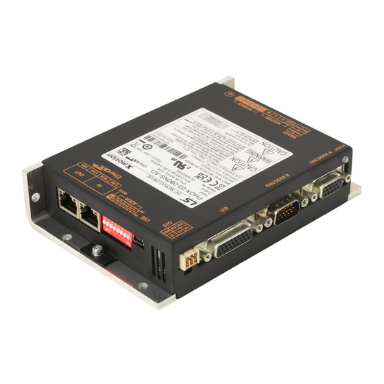
PHOX Series DC Servo Drive
AutomationDirect Foreword
This QuickStart Guide is designed to get a PHOX servo system installed and running quickly.
This AutomationDirect Guide is a supplement to the LS Electric PHOX User Manual. This Guide
does not replace the manufacturer's User Manual. For advanced features or options required
by your application, you may still need to refer to the User Manual. Download and reference
both this QuickStart Guide and the PHOX User Manual when commissioning a PHOX servo
system.
This quickstart guide will get your PHOX drive configured and commissioned using Drive CM.
• For further EtherCAT commissioning help, see AutomationDirect's LS Electric Interactive PLC
Guide available at
A note on Part Numbers: LS Electric servo parts sold by AutomationDirect have part numbers
that end with "-AD". This suffix signifies special packaging and labeling for AutomationDirect.
All the LS servo products with the "-AD" function and behave exactly the same as the standard
LS Electric parts. Please note that when reading the LS electric User Manual or using the Drive
CM software, the "-AD" will NOT appear in any part numbers. For example, AutomationDirect
part PHOX-06-080NS-AD is just PHOX-06-080NS in the LS Electric documentation.
NOTE: EtherCAT® is a registered trademark and patented technology, licensed by Beckhoff
Automation GmbH, Germany.
Quick Start Guide
https://cdn.automationdirect.com/static/helpfiles/ls_plc/Content/Home.htm
1st Edition, July 2nd, 2024
Advertisement
Table of Contents

Related Manuals for AutomationDirect LS Electric PHOX Series


Summary of Contents for AutomationDirect LS Electric PHOX Series
- Page 1 This QuickStart Guide is designed to get a PHOX servo system installed and running quickly. This AutomationDirect Guide is a supplement to the LS Electric PHOX User Manual. This Guide does not replace the manufacturer’s User Manual. For advanced features or options required by your application, you may still need to refer to the User Manual.
-
Page 2: Table Of Contents
AutomationDirect Foreword ........ -
Page 3: Phox Series Servo System Overview
PHOX Series DC Servo Drives Quick Start Guide PHOX Series Servo System Overview Warnings and Cautions WARNING: • Install both the servo drive and the servo motor before performing any wiring. • Before wiring or inspecting, turn off the power, wait 15 minutes, make sure the charge lamp is off, and check the voltage. -
Page 4: Installation
PHOX Series DC Servo Drives Quick Start Guide Installation Ambient Installation Conditions The PHOX Servo and compatible motors should be installed under the environmental conditions detailed below. Exceeding these conditions risks damage to the equipment. Condition Requirement Notes Install a cooling fan on the control panel for Operating Temperature 0–50°C [32–122 °F] ventilation and to maintain the temperature within the... -
Page 5: Quick Start Instructions
PHOX Series DC Servo Drives Quick Start Guide Quick Start Instructions To verify your servo components and motor/drive wiring as quickly as possible, please follow the steps below. These basic instructions will quickly get the motor spinning (verifying that parts and power wiring are correct). - Page 6 PHOX Series DC Servo Drives Quick Start Guide Step 3: Connect the PC to the Drive Substep Task Using a standard USB A to USB mini-B cable (such as SV2-PGM-USB15, MOSAIC-CSU, etc.), connect the PC to the Drive. Start Drive CM software. Select PHOX: LV DC and press the Connect button.
- Page 7 PHOX Series DC Servo Drives Quick Start Guide Step 6: Jog the Motor Substep Task Remove power from the drive. Ensure that there is nothing attached to the motor shaft. Initial motion testing should always be done with the motor uncoupled. Connect the motor power cable and re-apply power to the drive.
-
Page 8: First Time Inspection
Part Number Explanation The two-digit number in the middle of the drive part number determines the current output of the drive. Note that the “-AD” simply represents special packaging for AutomationDirect. These are standard LS Electric parts. For example: • PHOX-03-080NS-AD •... -
Page 9: Apmc Servo Motor
• -8 = 8V/krpm of back EMF and is only applicable to low voltage DC powered servo motors. For example: APMC-FAL01AM8N-8-AD This represents a 48 VDC motor, 40mm square, 1 Amp power, 3000rpm rated speed, 18-bit encoder, smooth shaft with no key way, with no brake, specially packaged for AutomationDirect. FAL/FBL Braking Motors FAL/FBL Motors Encoder... -
Page 10: Basic Inspection
Make sure the external voltage level of the servo drive is correct. The encoder cable should be protected from excessive stress – make sure the cable is not worn or stretched. Contact AutomationDirect if the servo motor vibrates or makes unusual noise during operation. Inspection before Make sure the parameter settings are correct. -
Page 11: System Wiring
(brake cables are only applicable for brake motors). They are available in lengths of 3m, 5m, 10m, and 20m (9.8 ft, 16.4 ft, 32.8 ft, and 65.6 ft). For cable model details and specifications, please see www.automationdirect.com. For assistance in specifying a servo system, go to www.automationdirect.com/selectors... - Page 12 Choose either Terminal Block + CN1 cable or a CN1 cable with labeled flying leads. APCS-PHOX-IOT-AD, APCS-PHOX-IOT01-AD, APCS-PHOX-IOT015-AD, APCS-PHOX-IOT02-AD Drive I/O Cables You can download a printable terminal label (“I/O Breakout Template”) at https://www.automationdirect.com/pn/APCS-PHOX-IOT-AD See terminal assignments table on the following page. APCS-PHOX-IO01A-AD, APCS-PHOX-IO02A-AD, APCS-PHOX-IO03A-AD (see pinout on next page)
-
Page 13: Names And Functions Of Brake Connector
Yellow/Black Stripe (B13) Yellow/Red Stripe White/Black Stripe You can download a printable terminal White/Red Stripe label (“I/O Breakout Template”) at White/Black Stripe https://www.automationdirect.com/pn/ White/Red Stripe APCS-PHOX-IOT01-AD DOCOM Common White/Black Stripe AGND White/Red Stripe Names and Functions of Brake Connector Name... -
Page 14: General Wiring Overview
PHOX Series DC Servo Drives Quick Start Guide General Wiring Overview Example System Configuration Os cillos cope Analog Monitor I/O C able ENC A ENC B S afety Devic e HO ME 1 03 14 1 03 14 1 03 14 Mini US B Motor Motor C able... -
Page 15: Main Power Connection Wiring
PHOX Series DC Servo Drives Quick Start Guide Main Power Connection Wiring The PHOX drive can accept 24-80 VDC input. The PHOX motor/drive combination supplies 300% rated maximum/intermittent motor torque. Speed torque curves are established using nominal 48VDC input power. 24-80 VDC 24-80 VDC AUX+... - Page 16 PHOX Series DC Servo Drives Quick Start Guide Power Connector Signal Names Signal Name Pin # Description Frame ground, for motor power cable. Connect the machine ground point to the ground screw located on the drive frame/heatsink. These are the motor U, V, and W outputs. These are the main power inputs.
-
Page 17: I/O Connection Wiring Diagram With Default Functions
PHOX Series DC Servo Drives Quick Start Guide I/O Connection Wiring Diagram with Default Functions I/O Connection wiring diagram is shown below. For a printable terminal label, go to: https://www.automationdirect.com/pn/APCS-PHOX-IOT01-AD See “Terminal Assignments and Wire Colors” on page 13 for terminal assignments. Note: Use the dedicated brake connector output to control the brake instead of DO1. - Page 18 PHOX Series DC Servo Drives Quick Start Guide Drive Node Address Setting and EtherCAT Basics Addres s (1~ 7), F ac tory purpose (8) The PHOX drive can be used in an EtherCat network. The node address of the drive is determined by the 7 dip switches on the side of the drive.
- Page 19 PHOX Series DC Servo Drives Quick Start Guide Digital Outputs 1) You can set the output to contact A (normally open) or Contact B (normally closed). 2) You can assign each output contact to one of 19 output functions. 3) For more information on signal assignment and change of the output contact, refer to the User Manual, section 5.1 “Setting for Input/Output Signals.”...
- Page 20 At the time of publication, the PHOX servo drive does not have 3rd party certification for Safe Torque Off (STO). Until the PHOX drive STO receives certification, AutomationDirect recommends having the machine’s safety circuit drop the motor power supply (not control power) when E-stop conditions are met. See section 6.2 of the PHOX user manual for details on connecting the STO circuit.
-
Page 21: I/O Wiring And Option Details For The Analog Input
• Torque limit: Can be used in index operation mode and EtherCAT operation mode while the indexing operation is performed. Using an FA-DCDC-1 DC-to-DC converter and the ECX2300-10K potentiometer from AutomationDirect is a good option for providing a +5 to -5 volt supply and control signal. -
Page 22: Status Led Display
PHOX Series DC Servo Drives Quick Start Guide Status LED Display The status LEDs on the front of the drive indicate the states and errors of the drive, as shown in the following figure. The status LED uses two colors (green and red) to indicate a total of 7 states. The green LED shows the servo operation status and the red LED shows hte servo error status. -
Page 23: Drive Cm Software
This USB cable is helpful when dealing with PC to Drive connectivity issues due to EMI) Step 1 Download and install Drive CM Software from the AutomationDirect software download page at https://www.automationdirect.com/support/software-downloads?itemcode=Drive%20CM%20 Configuration. Step 2 Connect the servo drive USB port to the PC USB port using a standard USB-A to USB-mini-B cable. - Page 24 PHOX Series DC Servo Drives Quick Start Guide Step 3 Open Drive CM Software and Connect to the drive. 1) Select the USB connection type and PHOX drive. 2) Then press the Cable icon to connect and establish communications with the drive. Push to connect After connecting, icon will change...
-
Page 25: Using The Drive Cm Software
PHOX Series DC Servo Drives Quick Start Guide Using the Drive CM Software There are two main working areas in Drive CM. The Main Window (larger, left) is mostly used for setup and configuration. The Auxiliary Window (smaller, right) has more dynamic operations available. Both areas can be viewed simultaneously for maximum usefulness. - Page 26 PHOX Series DC Servo Drives Quick Start Guide Toolbar Functions Icon Function Displays In Trace/Trigger Monitor (Scope) Cyclic Monitor (System Data View) Motor Encoder Setup (no configuration needed for auto-identifiable FBL/FCL motors) General Configuration Setup Main Window Fault Configuration Controls Loop (Manual Tuning) NOTE: Some Object Dictionary (Parameters) configuration screens...
-
Page 27: I/O Configuration
PHOX Series DC Servo Drives Quick Start Guide I/O Configuration Digital Inputs Use the following parameters to configure Digital Input functionality or use the Digital Input window in Drive CM directly to make changes. The software provides a very easy way to change the DI functions using the digital input icon (quickest and easiest method for configuration). - Page 28 PHOX Series DC Servo Drives Quick Start Guide Digital Input Codes See sections 2.4.1 and 5.1.1 in the User Manual for more information about DI codes. Drive CM is the easiest way to edit the DI codes - including changing the NO and NC settings. Either enter values directly into Parameters 0x2200–0x2203 (Object Dictionary’s I/O tab) or use the pulldown lists after selecting the Digital Input icon.
-
Page 29: Digital Outputs
PHOX Series DC Servo Drives Quick Start Guide Digital Outputs Use the following parameters to configure Digital Output functionality or use the Digital Output window in Drive CM directly to make changes. All four digital outputs are configurable. The software provides a very easy way to change the DO functions using the digital output icon (the quickest and easiest method of configuration). -
Page 30: I/O Connection - Analog Torque Input
PHOX Series DC Servo Drives Quick Start Guide Digital Output Codes See section 2.5.1 and 5.1.2 in the user manual for more information about DO codes. Drive CM is the easiest way to edit the DO Codes, including changing the NO and NC settings. Either enter values directly into Parameters 0x2210–0x2213 (Object Dictionary’s I/O tab) or use the pulldown lists after selecting the Digital Output icon. -
Page 31: Encoder Configuration Explanation
PHOX Series DC Servo Drives Quick Start Guide Index Position Mode Indexing Position Mode using the Setup Wizard for Simple Motion Commissioning Below is a simple walk through of minimal settings to establish an index application. Other object configuration settings may be required for your specific needs. See the User Manual for details Step 1: Drive Selection Substep Task... - Page 32 PHOX Series DC Servo Drives Quick Start Guide Step 3: Motor Setup Substep Task Input the motor ID attached to the drive. This is located on the motor nameplate or refer to the table below. Phox Motor APMC-FAL01AM8N-8-AD APMC-FAL01AM8N2-8-AD APMC-FBL01AMK-8-AD APMC-FBL01AMK2-8-AD APMC-FBL02AMK-8-AD APMC-FBL02AMK2-8-AD...
- Page 33 PHOX Series DC Servo Drives Quick Start Guide Step 4: Encoder Setup Substep Task If using a standard LS Electric low voltage motor (APMC-xxxxxx-8-AD, choose BiSS, Port A for Encoder Type. This is object 0x2001. If using a 40mm 100W FAL motor (APMC-FAL01AM8Nx-8-AD) choose a Resolution (0x2002) of 262144. This is the 18-bit encoder.
- Page 34 PHOX Series DC Servo Drives Quick Start Guide Step 5: Control Mode Selection Substep Task On the Select Control Mode screen, select Index Position for Control Mode (Object 0x3000). Click Next. PHOX Servo Drives Quick Start Guide – 1st Edition 07/02/2024 Page 34 of 74...
- Page 35 Set Index Buffer Mode (Object 0x3009) allows you to trigger the START signal once or twice. In this example, Single buffer set is selected. [AutomationDirect advises using Single buffer set] Set IOUT Configuration (Object 0x300A). For a full description of each of these bit selections please see object 0x3004 details in the PHOX user manual.
- Page 36 PHOX Series DC Servo Drives Quick Start Guide Step 7: Set Rotation Direction Substep Task Click Next to set the Rotation Direction. This sets which motor direction is considered positive or negative. If this isn’t known, it can be set later in 0x2004 (in the Object Dictionary \ Basic tab). Click Next.
- Page 37 PHOX Series DC Servo Drives Quick Start Guide Step 9: Set Emergency Stop and Dynamic Brake Control Substep Task For initial setup and testing, choose the defaults for these settings on the Emergency Stop Configuration and Dynamic Brake Control Mode screen. More information can be found in the User Manual under Dynamic Brake Control Mode (0x2012) and Emergency Stop Configuration (0x2013).
- Page 38 PHOX Series DC Servo Drives Quick Start Guide Step 11: Set the Torque Limit Function Substep Task Set the Torque Limit Function. Select a method for limiting the torque (0x2110) applied to the load while the motor is trying to attain commanded speed and final position.
- Page 39 PHOX Series DC Servo Drives Quick Start Guide Step 13: Set the I/O Signal Setting Substep Task Configure Inputs 1 through 4 as shown below on the Digital Input screen. Configure additional inputs as needed for your application. The filter column allows for filtering out EMI and false triggering. 1 millisecond is the default and multiple processor cycles can be added to the filter time.
- Page 40 PHOX Series DC Servo Drives Quick Start Guide Step 14: Set the Analog Monitor Mode Substep Task Objects 0x2220–0x2226 are used to configure Ch1 and Ch2 of the analog output monitoring terminals. There are 22 different drive status variables you can monitor using the analog output pins. See section 2.4.4 in the User Manual for more details.
- Page 41 PHOX Series DC Servo Drives Quick Start Guide Step 16: Save Your Configuration Substep Task Select Save to File to save the configuration file to your PC. Select Write to Drive to download the configuration to the drive. The drive MUST NOT be enabled during download.
- Page 42 PHOX Series DC Servo Drives Quick Start Guide Step 17: Open Index Edit and Index Test Windows Substep Task Click the Index Edit button on the Drive CM toolbar. Configure Index 0, Index 1, Index 2, and Index 3 per the image below: After each entry the text will turn red indicating it has not been downloaded to the drive.
-
Page 43: Pulse Input Position Mode
PHOX Series DC Servo Drives Quick Start Guide Pulse Input Position Mode Pulse Input Position Mode Using the Setup Wizard for Simple Motion Commissioning Below is a simple walkthrough of minimal settings to establish a pulse input controlled application. Other object configuration settings may be required for your specific needs. See the User Manual for details Step 1: Drive Selection Substep... - Page 44 PHOX Series DC Servo Drives Quick Start Guide Step 3: Motor Setup Substep Task Input the motor ID attached to the drive. This is located on the motor nameplate or refer to the table below. Phox Motor APMC-FAL01AM8N-8-AD APMC-FAL01AM8N2-8-AD APMC-FBL01AMK-8-AD APMC-FBL01AMK2-8-AD APMC-FBL02AMK-8-AD APMC-FBL02AMK2-8-AD...
- Page 45 PHOX Series DC Servo Drives Quick Start Guide Step 4: Encoder Setup Substep Task If using a standard LS Electric low voltage motor (APMC-xxxxxx-8-AD, choose BiSS, Port A for Encoder Type. This is object 0x2001. If using a 40mm 100W FAL motor (APMC-FAL01AM8Nx-8-AD) choose a Resolution (0x2002) of 262144. This is the 18-bit encoder.
- Page 46 PHOX Series DC Servo Drives Quick Start Guide Step 5: Control Mode Selection Substep Task On the Select Control Mode screen, select Pulse Input Position (1) for Control Mode (Object 0x3000). See section 10.3 for more details on Pulse Input Position Operation. Click Next.
- Page 47 PHOX Series DC Servo Drives Quick Start Guide Step 7: Set Electronic Gear Ratio Substep Task On the Electronic Gear Ratio screen, enter the resolution of the motor’s encoder (18-bit=262144 or 19- bit=524288 ppr)(Object 6091:1). This value should be the same number entered in “Encoder Setup” step (4A).
- Page 48 PHOX Series DC Servo Drives Quick Start Guide Step 8: Set Emergency Stop and Dynamic Brake Control Substep Task For initial setup and testing, choose the defaults for these settings on the Emergency Stop Configuration and Dynamic Brake Control Mode screen. More information can be found in the User Manual under Dynamic Brake Control Mode (0x2012) and Emergency Stop Configuration (0x2013).
- Page 49 PHOX Series DC Servo Drives Quick Start Guide Step 10: Set Torque Limit Function Substep Task Set the Torque Limit Function. Select a method for limiting the torque (0x2110) applied to the load while the motor is trying to attain commanded speed and final position.
- Page 50 PHOX Series DC Servo Drives Quick Start Guide Step 11: Set Signals Related to Position Control Substep Task On the Signals Related to Position Control screen, configure the “In Position” signals if you will use Digital Outputs INPOS1 and INPOS2. Click Next.
- Page 51 PHOX Series DC Servo Drives Quick Start Guide Step 13: Set the Analog Monitor Mode Substep Task Objects 0x2220–0x2226 are used to configure Ch1 and Ch2 of the analog output monitoring terminals. There are 25 different drive status variables you can monitor using the analog output pins. See section 2.4.4 in the User Manual for more details.
- Page 52 PHOX Series DC Servo Drives Quick Start Guide Step 15: Save Your Configuration Substep Task Select Save to File to save the configuration file to your PC. Select Write to Drive to download the configuration to the drive. The drive MUST NOT be enabled during download.
-
Page 53: Velocity Mode
PHOX Series DC Servo Drives Quick Start Guide Velocity Mode Velocity Mode (Speed Command) using the Setup Wizard for Simple Motion Commissioning Below is a simple walk through to establish a speed application with a variable torque limit. Other object configuration settings may be required for your specific needs. See the user manual for details. The example below will allow the application to select between 8 preset speeds (saved in the drive) and/or the analog speed input. - Page 54 PHOX Series DC Servo Drives Quick Start Guide Step 3: Motor Setup Substep Task Input the motor ID attached to the drive. This is located on the motor nameplate or refer to the table below. Phox Motor APMC-FAL01AM8N-8-AD APMC-FAL01AM8N2-8-AD APMC-FBL01AMK-8-AD APMC-FBL01AMK2-8-AD APMC-FBL02AMK-8-AD APMC-FBL02AMK2-8-AD...
- Page 55 PHOX Series DC Servo Drives Quick Start Guide Step 4: Encoder Setup Substep Task If using a standard LS Electric low voltage motor (APMC-xxxxxx-8-AD, choose BiSS, Port A for Encoder Type. This is object 0x2001. If using a 40mm 100W FAL motor (APMC-FAL01AM8Nx-8-AD) choose a Resolution (0x2002) of 262144. This is the 18-bit encoder.
- Page 56 PHOX Series DC Servo Drives Quick Start Guide Step 5: Control Mode Selection Substep Task On the Select Control Mode screen, select Velocity (2) for Control Mode (Object 0x3000). Click Next. On the Velocity Command Switch Select screen, select the desired velocity command. In the example below, Analog Velocity/SPD1, SPD2, SPD3 Input (2) (Object 0x231A) is selected.
- Page 57 PHOX Series DC Servo Drives Quick Start Guide Step 6: Set Analog Velocity Command and Clamp Level Substep Task Set the Analog Velocity Command Scale (Object 0x2229). The analog signal is set for +/-5V = +/- 500rpm (100rpm/V x 5V). For initial testing and setup, leave these settings at default values. If your application needs different scaling, adjust these settings.
- Page 58 PHOX Series DC Servo Drives Quick Start Guide Step 8: Set Electronic Gear Ratio Substep Task Leave the Electronic Gear Ratio settings at default values. They have no affect on Velocity Mode. [This step is performed on the same screen as Electronic Gear Ratio]. Configure the Encoder Output signal if desired.
- Page 59 PHOX Series DC Servo Drives Quick Start Guide Step 10: Set Brake Signal Setting Substep Task For initial setup and testing, choose the defaults for these settings on the Brake Signal Setting screen. More information can be found in the User Manual under Brake Output Speed (0x2407), Brake Output Delay Time (0x2408), and PWM Brake Delay Off Time (0x2011).
- Page 60 PHOX Series DC Servo Drives Quick Start Guide Step 11: Set Torque Limit Function Substep Task Set the Torque Limit Function. Select a method for limiting the torque (0x2110) applied to the load while the motor is trying to attain commanded speed.
- Page 61 PHOX Series DC Servo Drives Quick Start Guide Step 12: Set Signals Related to Speed Control Substep Task On the Signals Related to Speed Control screen, configure the speed output ranges that will trigger the digital outputs ZSPD, TGON, and INSPD. For initial testing and setup, these can be left as default. For more information, see section 11.4.3 Signals Related with Speed Control in the User Manual.
- Page 62 PHOX Series DC Servo Drives Quick Start Guide Step 14: Set the Analog Monitor Mode Substep Task Objects 0x2220–0x2226 are used to configure Ch1 and Ch2 of the analog output monitoring terminals. There are 22 different drive status variables you can monitor using the analog output pins. See section 7.5 in the User Manual for more details.
-
Page 63: Torque Mode
PHOX Series DC Servo Drives Quick Start Guide Torque Mode Torque Mode Using the Setup Wizard for Simple Motion Commissioning Below is a simple walk through of minimal settings to establish a variable torque application with a variable speed limit. Other object configuration settings may be required for your specific needs. See the User Manual for details. - Page 64 PHOX Series DC Servo Drives Quick Start Guide Step 3: Motor Setup Substep Task Input the motor ID attached to the drive. This is located on the motor nameplate or refer to the table below. Phox Motor APMC-FAL01AM8N-8-AD APMC-FAL01AM8N2-8-AD APMC-FBL01AMK-8-AD APMC-FBL01AMK2-8-AD APMC-FBL02AMK-8-AD APMC-FBL02AMK2-8-AD...
- Page 65 PHOX Series DC Servo Drives Quick Start Guide Step 4: Encoder Setup Substep Task If using a standard LS Electric low voltage motor (APMC-xxxxxx-8-AD, choose BiSS, Port A for Encoder Type. This is object 0x2001. If using a 40mm 100W FAL motor (APMC-FAL01AM8Nx-8-AD) choose a Resolution (0x2002) of 262144. This is the 18-bit encoder.
- Page 66 PHOX Series DC Servo Drives Quick Start Guide Step 5: Control Mode Selection Substep Task On the Select Control Mode screen, select Torque (3) for Control Mode (Object 0x3000). Click Next. Set the Analog Torque Command Scale (Object 0x221C). This is how much rated torque you want the motor to output at every volt increment when using the analog input.
- Page 67 PHOX Series DC Servo Drives Quick Start Guide Step 7: Set Electronic Gear Ratio Substep Task Leave the Electronic Gear Ratio settings at default values. They have no affect on Torque Mode. If your application will use the Encoder Output, enter the desired pulses per revolution and Output Mode/Logic.
- Page 68 PHOX Series DC Servo Drives Quick Start Guide Step 9: Set Brake Signal Setting Substep Task For initial setup and testing, choose the defaults for these settings on the Brake Signal Setting screen. More information can be found in the User Manual under Brake Output Speed (0x2407), Brake Output Delay Time (0x2408), and PWM Brake Delay Off Time (0x2011).
- Page 69 PHOX Series DC Servo Drives Quick Start Guide Step 10: Set Torque Limit Function Substep Task Set the Torque Limit Function. Select a method for limiting the torque applied to the load (0x2110). Here the Analog Torque Limit does not apply since the analog input must be used as a command and not a limit. Setting the desired torque limit registers will ensure Analog Torque command does not issue dangerous force on the load in either the FWD or REV direction.
- Page 70 PHOX Series DC Servo Drives Quick Start Guide Step 11: Set Signals Related to Speed Control Substep Task On the Signals Related to Speed Control screen, configure the speed output ranges that will trigger the digital outputs ZSPD, TGON, and INSPD. For initial testing and setup, these can be left as default. For more information, see section 11.4.3 Signals Related with Speed Control in the User Manual.
- Page 71 PHOX Series DC Servo Drives Quick Start Guide Step 13: Save Your Configuration Substep Task Select Save to File to save the configuration file to your PC. Select Write to Drive to download the configuration to the drive. The drive MUST NOT be enabled during download.
- Page 72 PHOX Series DC Servo Drives Quick Start Guide Encoder Configuration Explanation The Drive CM Setup Wizard steps you through the setup of the servo motor and encoder. This section adds more detail of how to manually setup the BiSS encoder configuration (for secondary encoders, non-LS BiSS encoders, etc.).
- Page 73 PHOX Series DC Servo Drives Quick Start Guide 5) Bit 20 (Status bit polarity) [0x02001013]: This will determine if the Error and Warning bits are active high or active low. This drive configuration bit is not part of the data length sum. a) 0= Active high b) 1= Active low 6) Bit 21 (Status bit position) [0x02001013]: This will configure the drive to expect the status bit to...
- Page 74 PHOX Series DC Servo Drives Quick Start Guide PHOX Servo Drives Quick Start Guide – 1st Edition 07/02/2024 Page 74 of 74...
Need help?
Do you have a question about the LS Electric PHOX Series and is the answer not in the manual?
Questions and answers