Table of Contents
Advertisement
Quick Links
Advertisement
Table of Contents

Related Manuals for ZOE PPM3

Summary of Contents for ZOE PPM3
- Page 1 Nightingale Monitoring System PPM3 User's Guide...
- Page 2 (except for brief excerpts in reviews and scientific papers) without the prior written consent of Zoe Medical. Zoe Medical makes no warranty of any kind on this material, including but not limited to, the implied warranties of merchantability and fitness for a particular purpose.
-
Page 3: User Assistance
User Assistance If you have a question or need help operating the Nightingale PPM3, please contact Zoe Medical Technical Support: Email: customersupport@zoemedical.com Phone: (978) 887-4013 For the latest information about answers to frequently asked questions, please consult our web site: www.zoemedical.com... -
Page 5: Table Of Contents
Parts you should have ............. 2-1 2.2. Mounting solutions ..............2-2 2.3. How to Connect the PPM3 to Power and Communications ..2-3 2.3.1. Checklist before Connecting to Patient ......2-11 2.4. How to Connect the PPM3 to the Patient ......2-12 2.5. - Page 6 Non-Invasive Blood Pressure Monitoring........6-1 6.1. Overview of NBP Monitoring ............ 6-1 6.2. Getting Started with NBP on the PPM3 ........6-1 6.3. Checking the NBP Measurement ..........6-2 6.4. Pediatric Considerations ............6-6 6.5. Hypertensive Considerations ........... 6-6 6.6.
- Page 7 Strip Chart Recordings ............17-3 17.4. Trend Recordings ..............17-4 17.5. Recorder Messages............... 17-4 Troubleshooting ................18-1 PPM3 Monitor Settings ..............19-1 Accessories ................. 20-1 Cleaning ..................21-1 Maintenance and Storage ............22-1 22.1. PPM3 Functional Tests ............22-1 22.2.
- Page 8 22.6. Password Control ..............22-1 Disposal ..................23-1 Technical Data ................24-1 viii N i g h t i n g a l e P P M 3 U s e r ' s G u i d e April 2019...
- Page 9 Figure 7. Fully Engaged Power Connector .......... 1-7 Figure 8. PPM3 Front Panel ..............1-8 Figure 9. Sample of PPM3 Main Screen ..........1-10 Figure 10. PPM3 Startup Screen ............2-4 Figure 11. PPM3 Shutdown Screen ............ 2-5 Figure 12.
- Page 10 Figure 66. Wakeup From Standby Mode .......... 15-2 Figure 67. Main Screen With Battery Icon ........16-1 Figure 68. PPM3 Recorder Connection ..........17-1 Figure 69. Replacing Recorder Paper ..........17-1 Figure 70. Setup Recorder Menu ............17-2 N i g h t i n g a l e P P M 3 U s e r ' s G u i d e...
-
Page 11: General Information
Nightingale MPC (Multi-patient Console). For the sake of brevity, the term PPM3 is sometimes used in this document to refer to the Nightingale PPM3. The Nightingale MPC is the central monitoring station for the Nightingale Monitoring System. - Page 12 Indications for Use The Zoe Medical Nightingale Monitoring System is indicated for use in adult & pediatric patient populations. The Zoe Medical Nightingale Monitoring System facilitates the monitoring of: Impedance respiration Non-Invasive blood pressure Invasive blood pressure Body temperature Functional arterial oxygen saturation (SpO End-tidal &...
- Page 13 ECG parameter to determine heart rate may be clinically preferred. • Only use accessories approved by Zoe Medical for use with the Nightingale PPM3. WARNING – FLAMMABLE ANESTHETICS. An explosion hazard exists if the monitor is used in the presence of flammable anesthetics.
- Page 14 • Connected devices should be located outside of the patient vicinity (greater than 1.5 meters) if they do not comply with IEC 60601-1. • The PPM3 should not be connected to devices that are not described in this manual. • The over-all system leakage current should be tested and should comply with IEC 60601-1-1.
- Page 15 CAUTION – Do not operate the Nightingale PPM3 near high frequency emissions (e.g. microwaves). Note – The battery may need to be recharged if the Nightingale PPM3 has been powered off for an extended period of time. See the Battery Operation chapter of this manual for details regarding the battery.
-
Page 17: Overview
PPM3 fits into the Nightingale Monitoring System, and a description of how this User's Guide relates to other Nightingale Monitoring System documents. This chapter also provides a basic overview of the PPM3 user interface and a list of the PPM3's main features. -
Page 18: Scope Of This User's Guide
Overview Note - The PPM3 is also designed to function in a stand-alone mode, independent of the MPC. 1.2. Scope of this User's Guide This User's Guide provides healthcare professionals the information required for the safe and effective use of the Nightingale PPM3. -
Page 19: Ppm3 Diagrams
1.3. PPM3 Diagrams Keypad Control knob Power Figure 2. PPM3 Front View Indicator April 2019 N i g h t i n g a l e P P M 3 U s e r ' s G u i d e... -
Page 20: Figure 3. Ppm3 Rear View
Battery Charging Indicator On/Off Button Slot for Mounting Tab Figure 3. PPM3 Rear View N i g h t i n g a l e P P M 3 U s e r ' s G u i d e April 2019... -
Page 21: Figure 4. Ppm3 Left View
Exhaust Dual Channel Recorder Connector Figure 4. PPM3 Left View (with Oridion Microstream® CO and IBP) April 2019 N i g h t i n g a l e P P M 3 U s e r ' s G u i d e... -
Page 22: Figure 5. Ppm3 Right View
(or MPC Central Station) Serial Interface Connector Ethernet Network Connector Figure 5. PPM3 Right View N i g h t i n g a l e P P M 3 U s e r ' s G u i d e April 2019... -
Page 23: Figure 6. Partially Engaged Power Connector
Overview To engage power connector, align with hole as shown holding connector body at 45° angle to the case and press into monitor. Figure 6. Partially Engaged Power Connector When fully engaged rotate the connector body so that that it is parallel to the case. Figure 7. -
Page 24: Ppm3 User Interface
Overview 1.4. PPM3 User Interface The PPM3 user interface makes use of a control knob and a set of keys on the front panel keypad (for input) and a display screen and speaker (for output). The front panel looks like the following diagram:... - Page 25 You can use the MAIN SCREEN key to return to the normal Main Screen display. You can use the control knob to navigate the PPM3 menus. Turn the knob to the left to navigate to the left or up. Turn the knob to the right to navigate right or down.
-
Page 26: Figure 9. Sample Of Ppm3 Main Screen
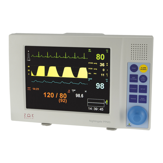
Area Figure 9. Sample of PPM3 Main Screen The Main Screen of the PPM3 has four areas ‒ one each for displaying waveforms, parameters, the patient information, and messages. The Waveform Area has five channels. Menu selections allow you to choose which waveform to display in which channel. -
Page 27: Main Features Of The Ppm3
The patient’s physiological signals and parameters are shown as waveforms and numbers on the PPM3 display. The PPM3 can be set up to generate an alarm when a physiological parameter goes beyond a preset limit. The PPM3 can also connect to a Nightingale MPC central monitoring station and send the waveform and parameter information to the MPC. -
Page 29: Getting Started
Chapter, to make sure that you know what all the part names mean. The first step in using the PPM3 is to make sure that you have all the parts you are going to need. Use the following list as a checklist: 1. -
Page 30: Mounting Solutions
Getting Started 2.2. Mounting solutions The PPM3 can be mounted to a roll stand or wall bracket using a custom adapter bracket that is described in the accessories chapter. The maximum height of a roll stand mount is 100 cm. -
Page 31: How To Connect The Ppm3 To Power And Communications
Communications CAUTION – Before making any connections, you need to figure out a good place to put the PPM3 in relation to the patient. This is important in order to avoid creating a situation where cables are hanging in places where they could get tangled up or trip someone. -
Page 32: Figure 10. Ppm3 Startup Screen
Getting Started Figure 10. PPM3 Startup Screen N i g h t i n g a l e P P M 3 U s e r ' s G u i d e April 2019... -
Page 33: Figure 11. Ppm3 Shutdown Screen
Getting Started To power-down the PPM3, press the On/Off Button until the following screen appears. The rest of the power-down process will be completed automatically. The power supply should remain connected for the battery to be recharged. Figure 11. PPM3 Shutdown Screen... - Page 34 Getting Started Connecting to an Electronic Medical Record (EMR) System Connection to an EMR system requires a custom Network Cable from Zoe Medical (Part Number 421-0052) or an equivalent cable configured as shown below. One end of the cable has a DB-9 connector that interfaces to a standard PC serial port.
- Page 35 Getting Started RJ45 Pin Signal DB9 Pin RX to monitor TX from monitor Ground April 2019 N i g h t i n g a l e P P M 3 U s e r ' s G u i d e...
- Page 36 1. Connect the Network Cable to the connector labeled on the right side of the PPM3. Then plug the other end of the Network Cable into PC that is hosting the EMR software. Note: For complete details of the communications protocol the PPM3 uses for interfacing with EMR systems, please refer to the document “PPM3 Data Transfer...
-
Page 37: Figure 12. New Patient Screen With Previous Patient
See the Working With Menus chapter for details on how to use the control knob to select the Yes/No menu items. Note – If you are using the Nightingale MPC for centralized monitoring, the PPM3 will not establish a connection until the New Patient question is answered. -
Page 38: Figure 13. Main Screen With No Patient Admitted
MPC. The waveforms and parameter values will not be displayed until you connect the PPM3 to the patient. 2-10 N i g h t i n g a l e P P M 3 U s e r ' s G u i d e... -
Page 39: Checklist Before Connecting To Patient
Checklist before Connecting to Patient Before connecting the PPM3 to a patient: 1. If connecting the PPM3 to a new patient, clean the unit according to the instructions in the Cleaning chapter. 2. Power up the unit, confirm that the startup tones sound (two tones followed by two higher-pitched beeps). -
Page 40: How To Connect The Ppm3 To The Patient
MPC, you should verify that the patient name is displayed in the name area of the PPM3 Main Screen. If the patient's name is too long to fit in this area, you should verify that the patient's initials are displayed. -
Page 41: Ecg And Heart Rate Monitoring
ECG Monitoring works through the sensing the electrical signals generated by the electrical activity of the heart as it beats. These signals are acquired from chest electrodes, and the PPM3 amplifies the signals so they can be displayed on the screen. The patient’s heart rate (HR) is calculated and continuously updated based on running average of the R to R intervals between each QRS complex. -
Page 42: Checking The Ecg Signal
When you have connected the patient following the steps listed above, you should be able to see a clean ECG signal similar to the figure below on the PPM3 display. If the ECG contains artifact or noise, review the steps for proper electrode site preparation and placement. - Page 43 ECG waveform and HR parameter return. The ECG and Heart Rate Monitoring settings and specifications for the Nightingale PPM3 may be found in the PPM3 Monitor Settings and Technical Data chapters. Procedures for changing configuration settings, such as sourcing...
- Page 44 – Note If an ECG waveform is not displaying on the PPM3, follow the instructions in the chapter Working With Menus to select one or more ECG waveforms for display. Note – Visually inspect the ECG cables on a daily basis and follow the instructions in the Cleaning and Maintenance chapters as needed.
-
Page 45: Standard Electrode Placement (Aha)
ECG and Heart Rate Monitoring 3.4. Standard Electrode Placement (AHA) For ECG cable lead sets with AHA (USA) lead designations, position the electrodes as shown in the following diagram: Note – If using a three-wire ECG cable lead set, you only need to apply the RA, LA, and LL electrodes, and only Lead II will be available. -
Page 46: Standard Electrode Placement (Iec)
ECG and Heart Rate Monitoring 3.5. Standard Electrode Placement (IEC) For ECG cable lead sets with IEC (Europe) lead designations, position the electrodes as shown in the following diagram: Note – If using a three-wire ECG cable lead set, you only need to apply the R, L and F electrodes, and only Lead II will be available. -
Page 47: Electrode Placement For Paced Patients (Aha)
ECG and Heart Rate Monitoring 3.6. Electrode Placement for Paced Patients (AHA) For ECG cable lead sets with AHA (USA) lead designations, the optimal electrode placement for patients with pacemakers may be as illustrated in the following diagram: Note – If using a three-wire ECG cable lead set, you only need to apply the RA, LA, and LL electrodes, and only Lead II will be available. -
Page 48: Electrode Placement For Paced Patients (Iec)
ECG and Heart Rate Monitoring 3.7. Electrode Placement for Paced Patients (IEC) For ECG cable lead sets with IEC (Europe) lead designations, the optimal electrode placement for patients with pacemakers may be as illustrated in the following diagram: Note – If using a three-wire ECG cable lead set, you only need to apply the R, L, and F electrodes, and only Lead II will be available. -
Page 49: Verifying Proper Pacemaker Handling
For paced patients, proper electrode placement results in pacer tick marks along the top of each ECG waveform channel on the Nightingale PPM3 and the MPC. These tick marks occur at the point where the PPM3 detects a pacer pulse. -
Page 50: Ecg And Heart Rate Monitoring Messages
ECG and Heart Rate Monitoring 3.9. ECG and Heart Rate Monitoring Messages Note – Factory default HR alarm and limit settings may be found in the PPM3 Monitor Settings chapter. Parameter Message Possible Cause Suggested Action Value The patient's heart rate... - Page 51 Loose lead wire Check to make sure the lead wires are Faulty lead wire HR lead off [blank] securely connected to the PPM3. Dried out electrode Check to make sure there are no Inoperable ECG circuit broken lead wires. Intentional removal by...
-
Page 53: Respiration Monitoring
When you have connected the patient to the monitor, you should be able to see a clean, slowly oscillating Respiration signal on the PPM3 display. This may take up to 30 seconds after the patient has been connected. The PPM3 should also display the patient's respiration rate (RR) and alarm limit settings. -
Page 54: Figure 19. Rr Waveform And Value
Respiration rates derived from CO parameter is not subject to such movement artifacts. Note – If the Respiration waveform is not currently selected for display on the PPM3, follow the instructions in the chapter on Working With Menus to select this waveform for display. -
Page 55: Pediatric Considerations
Respiration Monitoring 4.4. Pediatric Considerations Cardiogenic artifact (heart rate pulsations that appear as "breaths" in the respiration signal) can be quite pronounced in pediatric patients. This can cause the respiration rate to be artificially high (approaching the heart rate). To reduce cardiogenic artifact, move the White RA electrode (AHA lead designation) or the Red R electrode (IEC lead designation) from the right clavicle down to the right mid-clavical line, 4... -
Page 56: Respiration Monitoring Messages
Respiration Monitoring 4.5. Respiration Monitoring Messages Note – Factory default RR alarm and limit settings may be found in the PPM3 Monitor Settings chapter. Parameter Message Possible Cause Suggested Action Value The patient's respiration Check the patient and provide any rate has fallen below the necessary clinical care. -
Page 57: Pulse Oximetry Monitoring
60 second period to report the SpO value. The pulse oximetry monitoring capabilities of the Nightingale PPM3 include: • Measuring the functional oxygen saturation of the patient's arterial hemoglobin (SpO • Calculating the patient's pulse rate (PR) •... -
Page 58: Checking The Pulse Oximetry Signal
5.3. Checking the Pulse Oximetry Signal When you have connected the patient following the steps listed above, you should be able to see a clean pulse oximetry waveform on the PPM3 display as shown below. The PPM3 label for this waveform is SpO . - Page 59 Note – If the SpO waveform is not currently selected for display on the PPM3, follow the instructions in the chapter on Working With Menus to select this waveform for display. April 2019...
-
Page 60: Pediatric Considerations
The accuracy of a pulse oximeter probe or a pulse oximeter monitor cannot be assessed with a functional tester. The accuracy of the SpO parameter in the Nightingale PPM3 has been validated with a co-oximeter per ISO 80601-2-61. 5.4. Pediatric Considerations It is important to select a SpO sensor that is appropriate for the weight of the patient. -
Page 61: Pulse Oximetry Monitoring Messages
Pulse Oximetry Monitoring 5.5. Pulse Oximetry Monitoring Messages Note – Factory default SpO alarm and limit settings may be found in the PPM3 Monitor Settings chapter. Parameter Message Possible Cause Suggested Action Value The patient's oxygen Check the patient and provide any... - Page 62 Bad SpO sensor Replace the SpO sensor. replace sensor Incorrect set-up within Contact Zoe technical support. the PPM3. Check to make sure the SpO sensor sensor not is securely connected to the SpO unplugged [blank] connected to SpO...
-
Page 63: Non-Invasive Blood Pressure Monitoring
1. Attach the NBP cuff to the patient. Please refer to the Accessories chapter for a list of Zoe Medical approved NBP cuffs for use with the Nightingale PPM3. In order to get good quality NBP measurements, you need to use a cuff that is the appropriate size for the patient. -
Page 64: Checking The Nbp Measurement
Instruct the patient to remain quiet and still during the measurement. 2. Connect the NBP cuff to the NBP hose, and connect the hose to the PPM3. Try to allow 5 min elapse before taking the first measurement in Step 3. - Page 65 Verify that the alarm is no longer active. The NBP Monitoring settings and specifications for the Nightingale PPM3 may be found in the PPM3 Monitor Settings and Technical Data chapters. Procedures for changing configuration settings, such as enabling alarms, adjusting alarm limits, or setting up an automatic measurement interval, may be found in the Working With Menus chapter.
- Page 66 NBP Monitoring notifications. Use this feature with extreme caution. Patients must be closely observed if NBP limit alarms are disabled. WARNING – Be sure that the NBP hose is not kinked during a measurement. Kinks in the hose could lead to sustained pressure in the blood pressure cuff, which could cause limb damage to the patient.
- Page 67 Note – The Auto Mode setting is remembered between power cycles. However, the PPM3 does not start Auto Mode NBP measurements after power up until the NBP Start/Stop key is pressed. This tells the PPM3 that the cuff has been applied to the patient and that NBP monitoring should commence.
-
Page 68: Pediatric Considerations
PPM will use the previous systolic pressure value to select the inflation cuff pressure. The PPM3 automatically senses when an infant cuff is attached and limits the maximum cuff pressure to 180 mmHg, as opposed to 270 mmHg for larger cuffs. -
Page 69: Nbp Monitoring Messages
NBP Monitoring 6.6. NBP Monitoring Messages Note – Factory default NBP alarm and limit settings may be found in the PPM3 Monitor Settings chapter. Parameter Message Possible Cause Suggested Action Value The patient's systolic Check the patient and provide any pressure has fallen necessary clinical care. - Page 70 Monitor has detected a NBP problem detected Turn the monitor off, then on. hardware problem If message persists, contact Zoe technical support. Initial inflation pressure may not have been high Repeat the measurement (monitor will enough (if patient’s...
-
Page 71: Oridion Co Monitoring
(indicated by the presence of impedance respiration box with blue labels underneath the green HR parameter box), press the SETUP key on the PPM3, scroll the control knob to Parameters, press the knob, press on the highlighted "ETCO Enabled,"... -
Page 72: Integrated Pulmonary Index
When you have connected the patient following the steps listed above, you should be able to see a CO waveform on the PPM3 display as shown below. The PPM3 should also display values for the patient's end-tidal carbon dioxide (ETCO... -
Page 73: Figure 22. Oridion Co Waveform And Values
Also, since IPI is based on physiological parameters that can change with age, the Nightingale PPM3 will prompt you to pick from one of three pediatric age changes (1-3 years, 3-6 years, and 6-12 years) when using IPI with a pediatric patient type selected. -
Page 74: Figure 23. Integrated Pulmonary Index
According to Oridion Medical, the following table presents a guide for clinical intervention based on IPI numeric values. Contact Oridion Medical for further details on IPI clinical intervention. The Nightingale PPM3 supports an IPI low alarm limit such that an alarm is annunciated when the IPI value drops below a configured low alarm limit setting. - Page 75 "Occluded Line" will appear in the message area. Replace the sampling line once the "Occluded Line" message appears. CAUTION – The Nightingale PPM3 does not produce a CO alarms until a valid CO signal is obtained. This is intended to reduce nuisance alarms during initial patient connection.
- Page 76 Oridion CO Monitoring CAUTION – Before use, carefully read the Microstream® ETCO sampling lines Directions for Use. CAUTION – Only use Microstream® ETCO sampling lines to ensure the monitor functions properly. Note – When the caution message "Occluded Line" appears on the screen, indicating that the sampling line which is attached to the monitor is blocked, the monitor’s CO pump will stop pumping the patient’s breath into the monitor for testing.
-
Page 77: Oridion Co Monitoring Messages
Oridion CO Monitoring 7.5. Oridion CO Monitoring Messages Note – Factory default CO alarm and limit settings may be found in the PPM3 Monitor Settings chapter. Parameter Message Possible Cause Suggested Action Value The patient’s ETCO Check the patient and provide any necessary clinical care. - Page 78 Connect the CO sampling line to the PPM3. sampling line is not Unplugged Disable CO monitoring in the PPM3 connected. Parameters menu if these parameters are no longer clinically required. sampling line cannot Replace the sampling line. If connected be cleared due to...
-
Page 79: Figure 25. Masimo Irma Module With Airway Adapter
Two different Masimo capnography modules – the ISA and the – are available for use with the Nightingale PPM3. The Masimo ISA IRMA utilizes a non-invasive approach known as sidestream capnography, whereby a portion of a patient’s inhaled and exhaled gases are diverted into a disposable... -
Page 80: Masimo Co Monitoring
(indicated by the presence of impedance respiration box with blue labels underneath the green HR parameter box), press the SETUP key on the PPM3, scroll the control knob to Parameters, press the knob, press on the highlighted "ETCO Enabled,"... -
Page 81: Monitoring
Perform a tightness check of the breathing circuit. 5. With either the ISA or IRMA module the CO waveform and numeric parameter values should appear on the PPM3 main screen within a few seconds. Verify parameter values and waveforms for correctness. April 2019... -
Page 82: Checking The Co
First, either connect the patient to the Nightingale PPM3 using the above procedure or continue as follows with a patient who is already being monitored. Then, enable the alarms ETCO... -
Page 83: Masimo Led Indicator
The LEGI Status Indicator on the ISA module and the Status LED on the IRMA module may be interpreted according to the table presented below. Also consult any result messages the PPM3 may present as found in Section 8.6 – Masimo CO Monitoring Messages. - Page 84 WARNING (ISA) – Carefully route the sampling line to reduce the risk of patient entanglement or strangulation. WARNING (ISA) – Do not lift the ISA or the PPM3 monitor by the sampling line as it could disconnect from the ISA or PPM3, causing the ISA or PPM3 to fall on the patient.
- Page 85 WARNING (ISA) – Replace the sampling line if the sampling line input Occluded Line” message connector starts flashing red, or a "CO appears on the PPM3. WARNING (ISA) – No modification of this equipment is allowed without authorization of the manufacturer. If this equipment is modified, appropriate inspection and testing must be conducted to ensure continued safe operation.
- Page 86 Masimo CO Monitoring WARNING (ISA) – Exhaust gases should be returned to the patient circuit or to a scavenging system. WARNING (ISA) – Due to the risk of patient cross-infection, always use a bacteria filter on the exhaust port side if sampled gas is intended to be re-breathed.
- Page 87 Masimo CO Monitoring WARNINGS (IRMA) – Do not use the IRMA infant airway adapter with adults as this may cause excessive flow resistance. WARNINGS (IRMA) – Measurements can be affected by mobile and RF communications equipment. It should be assumed that the IRMA probe is used in the electromagnetic environment specified in this manual.
- Page 88 Masimo CO Monitoring CAUTION (ISA) – Do not operate the ISA sidestream gas analyzer outside the specified operating environment. CAUTION (ISA) – (U.S. only) Federal law restricts this device to sale by or on the order of a licensed healthcare practitioner. CAUTION (IRMA) –...
-
Page 89: Masimo Co Monitoring Messages
Masimo CO Monitoring 8.6. Masimo CO Monitoring Messages Note – Factory default CO alarm and limit settings may be found in the PPM3 Monitor Settings chapter. Parameter Message Possible Cause Suggested Action Value The patient’s ETCO Check the patient and provide any necessary clinical care. - Page 90 Follow the zeroing procedure provided in Needs Zeroing be removed. this chapter. Disconnect the module or adapter from ISA module or IRMA the PPM3 and then reconnect. Contact Check Sensor sensor have reported an technical support if the problem internal error. continues.
-
Page 91: Invasive Blood Pressure Monitoring
• Displaying P1and P2 values with a choice of P1 and P2 (default) or ART, PA, and CVP labels • Displaying P1 and P2 waveforms continuously To connect pressure transducers made by various manufacturers to the PPM3, Zoe provides a connector adapter kit (Part Number 350-0280). April 2019... - Page 92 P2 parameter boxes and waveform areas below SpO ), press the Setup key on the PPM3, scroll the control knob to Parameters and press, scroll to "IBP Channels," press the knob, and scroll from "None" to "1" or "2" pressing the knob to select your choice. Press the Main Screen key to apply the changes.
-
Page 93: Checking The Ibp Signal(S)
When you have connected the patient following the steps listed above, you should be able to see IBP waveform(s) on the PPM3 display as shown below. The PPM3 should also display values for the patient's P1 and P2 pressures (with correct formats and labels) as well as the alarm limit settings (shown as disabled for systolic, mean, and diastolic below). - Page 94 IBP Monitoring WARNING – Operating the Nightingale PPM3 with P1 and/or P2 alarm limits disabled means that no low or high P1 and/or P2 alarm conditions will product alarm notifications. Use this feature with extreme caution. Patients must be closely observed if P1 and/or P2 limit alarms are disabled.
-
Page 95: Ibp Monitoring Messages
IBP Monitoring 9.3. IBP Monitoring Messages Note – Factory default IBP alarm and limit settings may be found in the PPM3 Monitor Settings chapter. Note – Substitute P2 for P1 as required in the following table. Parameter Message Possible Cause... -
Page 97: Temperature Monitoring
1. Fully insert the probe into a probe cover. 2. Apply the probe to the patient Please refer to the Accessories chapter for a list of Zoe Medical approved temperature probes for use with the Nightingale PPM3. For oral application: Insert the probe as indicated in the Zoe Medical "Oral Temperature Probe Instructions,"... - Page 98 The Temperature Monitoring settings and specifications for the Nightingale PPM3 may be found in the PPM3 Monitor Settings and Technical Data chapters. Procedures for changing the units or adjusting alarm limits may be found in the Working With Menus chapter.
-
Page 99: Temperature Monitoring Messages
Temperature Monitoring 10.2. Temperature Monitoring Messages Note – Factory default Temperature alarm and limit settings may be found in the Menu Settings table in the PPM3 Monitor Settings chapter. Parameter Message Possible Cause Suggested Action Value Check the patient and provide any The patient's necessary clinical care. -
Page 101: Working With Menus
This chapter instructs you in how to use these parameter setup menus as well as the menus behind keys on the PPM3 front panel. Note – The complete list of factory default settings for the Nightingale PPM3 may be found in the PPM3 Monitor Settings chapter. -
Page 102: Parameter Menus
Working With Menus 11.1. Parameter Menus 11.1.1. ECG and Heart Rate Figure 31. Setup HR Menu Setting Description Lower Limit HR/PR alarm lower limit Upper Limit HR/PR alarm upper limit Auto-adjust lower limit to 80% of current value and upper limit to Auto 125% of current value. -
Page 103: Figure 32. Hr/Pr Values Sourced From Spo2 Or Art
Working With Menus Calculate HR/PR from ECG (default ‒ green), SpO (cyan), or ART- HR Source labeled IBP (red). See Figure 28 for HR/PR parameter box appearance when HR Source is SpO or ART. Enables audible tones for each detected beat. When source is Pulse Tone Source , the tone pitch varies (higher SpO % = higher pitch). -
Page 104: Respiration
Working With Menus 11.1.2. Respiration Figure 33. Setup RR Menu Setting Description Lower Limit RR alarm lower limit Upper Limit RR alarm upper limit Auto-adjust lower limit to 80% of current value and upper limit to Auto 125% of current value. Alarms On Enables (Yes) or disables (No) alarms Print on Alarm... -
Page 105: Pulse Oximetry
Working With Menus 11.1.3. Pulse Oximetry Figure 34. Setup SpO Menu Setting Description Lower Limit alarm lower limit Upper Limit alarm lower limit Auto-adjust SpO lower limit to 95% of current value and set Auto upper limit to 100%. Alarms On Enables (Yes) or disables (No) alarms Print on Alarm Print a strip chart summary upon alarm condition... - Page 106 Working With Menus , the tone pitch varies (higher SpO2 % = higher pitch) SpO2 Alarm Clears SpO alarms until a patient is once again detected at the Acknowledge sensor 11-6 N i g h t i n g a l e P P M 3 U s e r ' s G u i d e April 2019...
-
Page 107: Non-Invasive Blood Pressure
Working With Menus 11.1.4. Non-Invasive Blood Pressure Figure 35. Setup NBP Menu Setting Description Lower Limit NBP systolic/mean/ diastolic alarm lower limits Upper Limit NBP systolic/mean/ diastolic alarm upper limits Auto-adjust NBP lower limits to 80% of current values and upper Auto limits to 125% of current values. - Page 108 NBP Interval measurements after power up until the NBP Start/Stop key is pressed. This tells the PPM3 that the cuff has been applied to the patient and that NBP monitoring should commence. The NBP cuff is inflated to this pressure if a systolic pressure from Initial Inflation previous measurement is not displayed.
-
Page 109: Oridion Co / Capnography
Working With Menus 11.1.5. Oridion CO / Capnography Figure 36. Setup CO Menu With Oridion Capnography Setting Description Lower Limit ETCO , RRc, & IPI alarm lower limits Upper Limit ETCO , RRc, & FICO alarm upper limits Auto-adjust lower limits to 80% of current values and upper limits to Auto 125% of current values. -
Page 110: Masimo Co / Capnography
Working With Menus 11.1.6. Masimo CO / Capnography Figure 37. Setup CO Menu With Masimo Capnography Setting Description Lower Limit ETCO & RRc alarm lower limits Upper Limit ETCO , RRc, & FICO alarm upper limits Auto-adjust lower limits to 80% of current values and upper Auto limits to 125% of current values. - Page 111 Working With Menus Monitoring chapter) CO2 Alarm Clears CO alarms and parameter values until a patient is once Acknowledge again detected at the CO sensor 11-11 April 2019 N i g h t i n g a l e P P M 3 U s e r ' s G u i d e...
-
Page 112: Invasive Blood Pressure
Working With Menus 11.1.7. Invasive Blood Pressure Figure 38. Setup IBP Menu Setting Description Lower Limit P1 systolic/mean/diastolic alarm lower limits Upper Limit P1 systolic/mean/diastolic alarm upper limits Auto-adjust lower limits to 80% of current values and upper limits to Auto 125% of current values. -
Page 113: Temperature
Working With Menus 11.1.8. Temperature Figure 39. Setup TEMP Menu Setting Description Lower Limit TEMP alarm lower limit Upper Limit TEMP alarm upper limit Auto-adjust lower limit to 95% of current value and upper limit to Auto 105% of current value. Alarms On Enables (Yes) or disables (No) alarms Print on Alarm... -
Page 114: Front Panel Keypad Menus
11.2. Front Panel Keypad Menus 11.2.1. SETUP Key and Submenus When you press the SETUP key on the PPM3 front panel, the top-level Setup Menu appears. Figure 40. SETUP Key Menu This menu gives you access to a variety of functions and sub-menus. -
Page 115: Figure 41. Main Screen With Alarms Paused Message & Timer
Working With Menus If you select the "Alarm Pause" item, the PPM3 will temporarily disable all alarm monitoring. Selecting "Alarm Resume" from the same spot on the Setup Menu will resume alarm monitoring. An "Alarms Paused" condition is indicated in the message area with a timer indicating when alarm monitoring will resume. -
Page 116: Figure 42. Setup Parameters Menu
The Setup Parameters menu allows you to enable ETCO / Capnography) and IBP (Invasive Blood Pressure) Monitoring, if these components are present in your Nightingale PPM3 monitor, but have not been turned on from a software standpoint. 11-16 N i g h t i n g a l e P P M 3 U s e r ' s G u i d e... -
Page 117: Figure 43. Numbers Only Main Screen
Working With Menus If you change "Numbers Only" to "Yes," the Main Screen will display all the monitored physiological parameters with large numbers instead of sharing some of the space with waveforms. Figure 43. Numbers Only Main Screen 11-17 April 2019 N i g h t i n g a l e P P M 3 U s e r ' s G u i d e... -
Page 118: Figure 44. Setup Waveforms Menu
(five with two IBP channels enabled). The range of possible choices for the waveform display channels may be found in the Waveform Settings table in the PPM3 Monitor Settings chapter. For ECG and CO waveforms, you can also choose what size (amplitude) setting to use. For the CO... -
Page 119: Figure 45. Setup Waveform Menu With Ibps
MPC. In the case where the sweep speed is set to 50 mm/sec at the MPC, the PPM3 will use a 25 mm/sec sweep speed instead. This is the highest sweep speed that is supported by the PPM3. -
Page 120: Figure 46. Setup Audio Menu
Working With Menus If you select the "Audio" item, the Setup Audio Menu appears. Figure 46. Setup Audio Menu The Speaker Volume allows you to change the volume for alarm tones. The HR/PR Tone Volume allows you to change the volume for pulse tones. You can also enable the HR/PR Tone and select the source from this menu, just as you can from the Setup HR and Setup SpO menus. - Page 121 The factory default values and ranges of possible values for all alarm limits may be found in the Parameter Settings table of the PPM3 Monitor Settings chapter. When you select the "Auto" feature for a parameter’s alarms, the PPM3 automatically adjusts the upper and lower limits based on the current value of the parameter.
- Page 122 Working With Menus Parameter Lower limit adjustment Upper limit adjustment HR/PR, RR, Changed to 80% of the Changed to 125% of the ETCO , RRc current parameter value (or current parameter value (or NBPs/m/d, the nearest allowable value the nearest allowable value P1s/m/d, given alarm limit rules) given alarm limit rules)
- Page 123 Working With Menus Figure 48. Setup Alarms Menu – Screen 2 11-23 April 2019 N i g h t i n g a l e P P M 3 U s e r ' s G u i d e...
- Page 124 Working With Menus Figure 49. Setup Alarms Menu – Screen 3 11-24 N i g h t i n g a l e P P M 3 U s e r ' s G u i d e April 2019...
-
Page 125: Figure 50. Patient Information Menu
Nightingale MPC, entries made here when admitting a patient will be transmitted to the MPC. Also, if a patient is admitted at the MPC and assigned to a particular PPM3, the information will be transmitted to this menu. The Patient Information Menu is also the place to change the patient type from Adult to Pediatric. -
Page 126: Figure 52. Restore Department Defaults Menu
Department Default values. Or, if no Department Defaults have previously been created, the settings will be restored to the Factory Default values found in the PPM3 Monitor Settings chapter. Department Defaults can only be saved from within the password protected Setup System Menu. -
Page 127: Figure 53. Setup Administration Menu
Working With Menus If you select the "Administration" item, the Setup Administration Menu appears. Figure 53. Setup Administration Menu Each of the selections on this menu leads to further submenus. 11-27 April 2019 N i g h t i n g a l e P P M 3 U s e r ' s G u i d e... -
Page 128: Figure 54. Setup Configuration Menu
Figure 54. Setup Configuration Menu The Setup Configuration menu provides a way of seeing what hardware and software versions are currently installed on the Nightingale PPM3. 11-28 N i g h t i n g a l e P P M 3 U s e r ' s G u i d e... -
Page 129: Password Protected Menus
Password Protected Menus If you select "Alarms," "System," "Service," or "Factory" on the Setup Administration Menu, the PPM3 brings up the Enter Password Menu. Figure 55. Enter Password Menu This menu allows you to enter a password to proceed to the Setup Alarms or Setup System menu. -
Page 130: Figure 56. Setup Alarms Menu
Working With Menus The Setup Alarms Menu allows changes to certain aspects of alarm handling. Figure 56. Setup Alarms Menu 11-30 N i g h t i n g a l e P P M 3 U s e r ' s G u i d e April 2019... - Page 131 Working With Menus The settings that can be changed via the Setup Alarms menu include: Setting Description Time that alarm will be silenced after you press the Alarm Silence Time ALARM SILENCE key (unless a new alarm comes in) Time that alarms will be suspended after you select the Alarm Suspend Time Alarm Suspend item in the top level Setup menu This setting controls if the clinician is able to suspend all...
-
Page 132: Figure 57. Setup System Menu
Working With Menus The Setup System Menu allows changes to a few items that are rarely changed. Figure 57. Setup System Menu The settings that can be changed via the Setup System menu include: Setting Description Temp Units Allows you to choose °F or °C Height Units Allows you to choose inches (in) or centimeters (cm) Weight Units... -
Page 133: Figure 58. Set Date And Time Menu
Working With Menus If you select the "Select Date and Time" item, the Set Date and Time Menu appears. Figure 58. Set Date and Time Menu 11-33 April 2019 N i g h t i n g a l e P P M 3 U s e r ' s G u i d e... -
Page 134: Figure 59. Save Department Defaults Menu
Menu appears. Figure 59. Save Department Defaults Menu The Save Department Defaults menu allows you to configure the PPM3 for your particular application. Once the patient monitoring settings have been configured as desired, selecting this choice will allow you to save the current settings as the baseline for all new patients. -
Page 135: Nbp Interval Key
Working With Menus 11.2.3. NBP INTERVAL Key If you press the NBP INTERVAL key, the PPM3 brings up the menu that allows you to change the automatic NBP Interval Mode settings. Figure 60. Setup NBP Interval Menu To select an automatic NIBP interval: 1. - Page 136 Mode measurements after a Standby or a power cycle until the NBP START/STOP key is pressed. This tells the PPM3 that the cuff has been applied to the patient and that NBP monitoring should commence. Once the key has been pressed, the interval will display in the message area and the measurements will proceed thereafter based on the o’clock as per the system time.
-
Page 137: Standby Key
If you press the MAIN SCREEN key, the Nightingale PPM3 goes back to the Main Screen. Note – If a menu is on display when you press the MAIN SCREEN key, the PPM3 interprets this as if you had first selected the OK button on the menu. Any settings changes that would have been effected with the OK button are applied. -
Page 139: Managing Alarms
When the PPM3 and MPC are connected, they use the same alarm monitoring settings. If a setting is changed at either the PPM3 or the MPC, then the setting is updated at both the PPM3 and the MPC. This is also true for alarm silencing. For example, if you silence an alarm at the PPM3 by pressing the ALARM SILENCE key on the front panel keypad, it is also silenced at the MPC. -
Page 140: Alarm Presentation Basics
Managing Alarms 12.1. Alarm Presentation Basics There are three "grades" of alarms on the PPM3 – high, medium, and low – and they all present in different ways as described in the following two tables. 12.1.1. Audible Alarm Tones If you hear a…... -
Page 141: How To Silence Alarms
Since several parameters could be alarming at the same time, the alarm tone and color will reflect the highest grade alarm condition that is currently active on the PPM3. Refer to the tables in Section 11.2 Alarm Conditions to see how different alarm conditions are categorized by grade. -
Page 142: Alarm Messages
Managing Alarms If the alarm condition is still true when the "alarm silence time" expires (as configured in the Setup Alarms menu), then the backgrounds of the parameter box and message area will automatically resume flashing and the alarm tone resume as well. -
Page 143: How To Enable Or Disable Alarms
Managing Alarms 12.1.5. How to Enable or Disable Alarms Alarm conditions are not annunciated unless alarms are enabled for a given parameter. The enabling or disabling of alarms is done via the "Alarms On" selection item in the Setup Alarms menu or in the individual parameter setup menus. -
Page 144: Alarm Validation
12.1.7. Alarm Handling at Start-up When the PPM3 is initially powered-up or brought out of standby, alarms will not be annunciated for a given parameter until the lead set or probe has been applied to the patient. This prevents nuisance alarms for parameters that are not being monitored on a given patient. -
Page 145: Audible Alarm Tones While Connected To The Mpc
PPM3. The reports will remain in the PPM3 memory even if power is turned off. When the PPM3 is reconnected to the MPC, the reports are transferred to the MPC. Manually-generated reports (via the PPM3’s print key) are also stored while in Transport Mode, and are counted as... -
Page 146: Second Speaker Alarm Tones
Managing Alarms 12.1.10. Second Speaker Alarm Tones The second speaker feature of the Nightingale PPM3 enhances the alarm tone functionality by providing a completely independent backup to the monitor's main speaker. The way the second speaker works is very simple. Whenever the monitor starts sounding an audible tone for an alarm condition, it starts a timer. -
Page 147: Alarm Conditions
Managing Alarms 12.2. Alarm Conditions The tables in this section contain lists of all the conditions the PPM3 can detect for each parameter, along with alarm characteristics of the condition. The first row in each table contains the "normal condition" for the parameter, and the other rows contain the "alarm conditions"... - Page 148 Managing Alarms PPM3 Battery Conditions: Display Alarm Annunciation Condition Message Value Grade Type Battery okay None None Persistent Battery low Battery low One time HR Conditions: Display Alarm Annunciation Condition Message Value Grade Type HR within limits <Number> None None Persistent HR <...
- Page 149 Managing Alarms Conditions: Display Alarm Annunciation Condition Message Value Grade Type within limits <NUM> None None None < LL <NUM> Medium < LL Persistent > UL <NUM> Medium > UL Persistent Bad Probe replace sensor One Time Cannot regulate LED <Blank>...
- Page 150 Managing Alarms NBP Conditions: Display Alarm Annunciation Condition Message Value Grade Type NBPs within limits <NUM> None None None NBPs < LL <NUM> Medium NBPs < LL One Time NBPs > UL <NUM> Medium NBPs > UL One Time NBPm within limits <NUM>...
- Page 151 Managing Alarms FICO out of range (high) <Number > Medium out of range (high) Persistent CO2 Unplugged (after start- <Blank> None None Persistent up/standby) CO2 Unplugged (after line <Blank> unplugged One Time connected) Power up (10 to 30 seconds) <Blank> None warming up Persistent...
- Page 152 Managing Alarms Pressure signal out of range <Number > Medium P1 out of range (low) Persistent (low) No pulse rate due to static HR weak signal Persistent pressure Unplugged (after start- <Blank> None None Persistent up/standby) Unplugged (after line connected) <Blank>...
-
Page 153: What To Do When You Hear An Alarm Tone
12.3. What To Do When You Hear An Alarm Tone When you hear an alarm tone, you should look at the message area of the PPM3 display screen to see why the tone is sounding. The action you should take... -
Page 154: Manual Self-Test Of The Alarm System
"SpO unplugged." • If the PPM3 is being monitored at the MPC, then disconnect the PPM3 from the communications wall outlet. After 30 seconds, the PPM3 should sound a low grade alarm tone and display the message "MPC connection lost."... -
Page 155: Centralized Monitoring
In either case, you should see the patient name in the patient name area of the PPM3 main display screen. For new patients, it is a good idea to admit the patient at the MPC first, since you can then verify that the connection has been made correctly while you are at the patient's bedside. -
Page 156: Remote Control Settings
• NBP initial inflation pressure and auto-mode setting • Pulse tone source If a setting is changed at either the PPM3 or the MPC, the new setting is used at both the PPM3 and MPC. If a patient is already admitted at the PPM3 when a connection is initially made between the PPM3 and MPC, the PPM3 and MPC alarm settings are merged such that the more conservative settings are used. -
Page 157: Viewing Trends
If PR is being sourced from an ART-labeled IBP, there will be a PR column labeled in red. Up to 72 hours of trends data may be stored on the PPM3. All trend samples can be manually deleted via the trends menu. They are also deleted when a patient is discharged at the MPC. -
Page 158: Figure 62. Trends Menu
Strip Chart Recorder is configured with your PPM3 (see the Strip Chart Recorder Option chapter). If your PPM3 is connected to the MPC, this report will print out immediately on the printer configured with the MPC. Otherwise, the data will be stored internally, and will upload and print automatically the next time the PPM3 is connected to the MPC. -
Page 159: Figure 63. Clear Trends Menu
Viewing Trends The "Clear" menu item will cause all the trends data to be deleted. Before this happens, you will be prompted with the following confirmation. Figure 63. Clear Trends Menu 14-3 April 2019 N i g h t i n g a l e P P M 3 U s e r ' s G u i d e... -
Page 161: Entering Standby Mode
Entering Standby Mode 15. Entering Standby Mode If you press the "Standby" key while a patient is admitted to the PPM3, the PPM3 will present you with the various Standby Mode options. Figure 64. Standby Menu Select the "Enter Standby Mode" menu item if you wish to temporarily suspend all monitoring for this patient (say, when the patient is being bathed). -
Page 162: Figure 65. Standby Mode
Entering Standby Mode Figure 65. Standby Mode When a key is pressed the previous patient must be confirmed. If you select "No," that patient will be discharged and a new patient will be admitted. Navigate to the Setup Patient Information Menu to enter information for the new patient. Figure 66. - Page 163 Select the "Discharge Patient" menu item if you are finished monitoring this patient. This will de-assign the patient from both the PPM3 and MPC (although the patient’s trend data will still be archived at the MPC). In addition, the PPM3 will restore the monitor’s parameter and waveform settings to the Department Defaults (last saved setup), and suspend monitoring (as described above).
-
Page 165: Battery Operation
When the PPM3 is operating on battery power, a battery icon appears on the PPM3 screen to the right of the time. The battery icon is designed to give an approximate sense of how much battery life is remaining. - Page 166 PPM3 Main Screen (shown above). The toggle switch on the back of the PPM3 allows you to turn the PPM3 on and off. See the Maintenance chapter for details on how to have the battery replaced.
-
Page 167: Strip Chart Recorder Option
17.1. Basic Operation PPM3 monitors may be configured with an optional 50mm strip chart recorder available from Zoe Medical. To start a recording, press the Print key. When a recording is in progress, you can press the Print key to stop it. -
Page 168: Recorder Settings
Strip Chart Recorder Option 17.2. Recorder Settings If after pressing the SETUP key, you select the "Recorder" item, the Setup Recorder menu will appear. Figure 70. Setup Recorder Menu The Waveform 1 setting controls which waveform is shown in the top channel of the strip chart recordings. -
Page 169: Strip Chart Recordings
Strip Chart Recorder Option 17.3. Strip Chart Recordings Strip chart recordings contain a waveform area that includes a 40 mm-wide grid with descriptive text above and below the grid. The waveform grid has major divisions at 5 mm intervals and minor divisions at 1 mm intervals, in both the x and y direction. -
Page 170: Trend Recordings
Strip Chart Recorder Option 17.4. Trend Recordings When the recorder option is installed, the recorder can print out a Trend Report. This report contains the same information that is presented in the trends display, with the following additions: • A header that includes a Trend Report title and the date/time of the trend report. -
Page 171: Troubleshooting
18. Troubleshooting The following table is meant to help you solve problems that you may encounter while operating the PPM3. If you are still experiencing a problem and none of these steps seem to help, please contact Zoe Technical Support: WARNING –... - Page 172 Operating system failure PPM3, contact Zoe Medical Technical Support to request a repair or replacement The PPM3’s disk is too full and needs The PPM3 displays a message Stop using the PPM3, contact Zoe stating that the disk is too full.
-
Page 173: Ppm3 Monitor Settings
19. PPM3 Monitor Settings The following tables show the factory default settings (Patient Data, Parameter, Waveform, and Device) for the Nightingale PPM3 monitor. Note the differences in certain parameter settings for Adult and Pediatric patient types. You may adjust the parameter and waveform settings for your particular application, and then save this configuration as a department default for all new patients. - Page 174 PPM3 Monitor Settings Parameter Settings Setting name Default value Possible values Adult / Pediatric ETCO Enabled Yes, No IBP Channels None None, 1, 2 Numbers Only Yes, No HR Lower Alarm Limit 50 bpm 15 to 299 bpm, Off HR Upper Alarm Limit...
- Page 175 PPM3 Monitor Settings Parameter Settings Setting name Default value Possible values Adult / Pediatric O Compensation (Masimo) 0 to 30 0 to 30, 31 to 70 IPI Enabled (Oridion) Yes, No IPI Lower Limit 1 to 9, Off IPI Alarms On...
- Page 176 PPM3 Monitor Settings Parameter Settings Setting name Default value Possible values Adult / Pediatric P2m Alarms On Yes, No P2m Print on Alarm Yes, No P2d Lower Alarm Limit 55 mmHg -10 to 209 mmHg, Off P2d Upper Alarm Limit...
- Page 177 PPM3 Monitor Settings Waveform Settings Setting name Default Possible values value Channel 1 Waveform I, II, III, V, aVL, aVR, aVF Channel 2 Waveform RESP I, II, III, V, aVL, aVR, aVF, RESP, CO2 Channel 3 Waveform SpO2 I, II, III, V, aVL, aVR, aVF, SpO...
- Page 178 PPM3 Monitor Settings Device Settings Speaker Volume 1 to10 Pulse Tone Volume 1 to 10 Alarm Silence Time 1 minute 1, 2, or 3 minutes Alarm Pause Time 1 minute 1, 2, or 3 minutes Can Pause All Alarms Yes, No...
-
Page 179: Accessories
Accessories 20. Accessories The following table shows the accessories approved by Zoe Medical for use with the Nightingale PPM3. WARNING – Use only approved accessories with the PPM3. Using non-approved accessories may result in damage to the monitoring equipment, measurement error, or harm to the patient, and may void warranty coverage. - Page 180 TABLE STAND FOR PPM2 & PPM3 w-Recorder 180-8016 Pole Mount (C Clamp Mount) 180-8017 Roll Stand Kit 180-8014 Wall Mount Channel and Arm Kit. Requires PPM3 Pole Mount Power Supply 725-0037 PPM3 Power Supply 180-6001 Power Cord US (10 ft)
-
Page 181: Cleaning
Cleaning 21. Cleaning This table provides cleaning instructions for the PPM3, which should be cleaned monthly or as warranted. Accessories should be cleaned before application to a patient. Before cleaning, refer to the cautions listed after the table. Part Recommended cleaning method Materials •... - Page 182 Wipe off with cloth. Allow analyzer to dry before placing it on a patient. CAUTION – Always disconnect the PPM3 from AC mains before cleaning. CAUTION – Do not use harsh chemicals for cleaning – in particular, do not use disinfectants that contain phenol as they can spot plastics. Do not steam autoclave, gas sterilize, irradiate, subject to intense vacuum, or immerse in water or cleaning solution.
- Page 183 Cleaning warm air for 2 hours, then check to make sure all monitoring functions are still working properly. CAUTION – Take particular care when cleaning the NBP cuff, NBP hose, and NBP connector on the PPM to prevent fluid from entering the connectors.
-
Page 185: Maintenance And Storage
MAIN SCREEN key: verify that the Main Screen is displayed Power LED Verify that the green power LED is illuminated on the front of the PPM3. Battery Charging LED Verify that the green charging LED is illuminated on the back of the PPM3... - Page 186 Maintenance and Storage PPM3 Function Procedure when plugged into mains power. Speaker Power-cycle the PPM3 and verify that the power-up speaker test tones are generated. Second Speaker Power-cycle the PPM3 and verify that the power-up second speaker test tones are generated.
- Page 187 Procedure Oridion Microstream® CO NOTE: Use only certified calibration gas apparatus that has not reached its expiration date. This cal gas can be applied to the PPM3 patient monitor in pulses that simulate patient breaths. 1. Connect the supplied CO calibration FilterLine between the PPM3 and the cal gas canister.
- Page 188 ECG cable should be cleaned according to the instruction in the Cleaning chapter of this manual. To place the PPM3 back in service after maintenance has been performed, connect the PPM3 to a wall outlet, insuring that cables do not present a tripping hazard. 22-4...
-
Page 189: Ppm3 Calibration Procedures
CO module should be calibrated after 1200 hours of use. The number of hours until calibration is due may be found in the PPM3 event log, which is accessed by pressing the PPM3 SETUP Key, then selecting "Administration," then "System,” and then "Show Event Log."... - Page 190 Technical Support. If there is a failure in one of the above procedures, please contact Zoe Medical Technical Support. If a PPM3 unit needs to be returned to the factory for repair, Technical Support will provide a return authorization number.
-
Page 191: Battery Replacement
Maintenance and Storage 22.3. Battery Replacement The internal Lithium-Ion battery does not require any special maintenance. If the battery is no longer holding a charge, it may need to be replaced. Under normal conditions of use, the battery lifetime is around three years. The procedure for replacing the battery is as follows: 1. -
Page 192: Warranty
(30) days on expendable parts. This warranty shall become null and void if product has been repaired other than by Zoe Medical, Inc. (Zoe), or if the product has been subject to misuse, accident, negligence or abuse. - Page 193 Maintenance and Storage customer is responsible for shipping charges to send the monitor to Zoe Medical and for the return shipping back to the customer. If an estimate is required and the estimate of repairs is declined after the monitor has been evaluated at Zoe Medical, the customer is responsible for the evaluation fee ** plus the shipping back to the customer.
- Page 195 Maintenance and Storage 22.6. Password Control To access the Setup Alarms or Setup System menu, perform the following steps when presented with the Password menu: • Set Dial 1 to 49 • Set Dial 2 to 48 • Set Dial 3 to 46 •...
- Page 197 & calibration gases should be carried out according to the manufacturer’s recommendations. At the end of its useful life, the Nightingale PPM3 should be properly disposed of as well. In particular, the PPM3 contains a lithium coin battery, a lithium ion battery, and electronic circuit boards which should not be incinerated or exposed to extreme heat.
- Page 199 Technical Data 24. Technical Data General 11.3”W x 7.2”H x 2.4”D (288 mm x 182 mm x 60 mm) Dimensions Weight 4.5 lb (2.0 g), 5.0 lb w/ Oridion Microstream® CO (2.3 kg) Finish PC/ABS 100 – 240 VAC, 1.2 A max Power Requirements 50 –...
- Page 200 IPX1 dripping water; specifically, it indicates DRIP PROOF, a higher than ordinary level of protection from drips, leaks, and spills. External AC/DC power supply; only use Zoe Medical P/N 725- 0037-X Local Area Network interface Interface for Nightingale MPC central station Interface for Other Medical Devices –...
- Page 201 Technical Data Pulse Oximetry connector Non-Invasive Blood Pressure connector P1/P2 Invasive Blood Pressure (dual) connector for P1 and P2 TEMP Temperature connector Microstream® ETCO Oridion CO input connector Oridion CO exhaust connector ETCO Masimo CO module connector Battery Type Lithium-Ion Rechargeable Discharging Time 4 hours (minimum) Charging Time...
- Page 202 Technical Data Sweep Speed 6.25, 12.5, 25 mm/s Display Mode Eraser Bar Accessories 3-lead cable, 5-lead cable Input Connector 7-pin connector 3-lead cable: I, II, III, AVL, AVR, AVF Displayable Leads 5-lead cable: I, II, III, AVL, AVR, AVF, V HR Resolution 1 bpm (beats per minute) Measurement Range...
- Page 203 Technical Data Active Noise Suppression RL drive (< 5 µA) Pulse Tone Respiration Method Impedance Pneumography Input Connector Same as ECG Sensing Lead RR Resolution 1 bpm (breaths per minute) Measurement Range 0 to 120 bpm Measurement Accuracy ±3 bpm Measurement Sensitivity 0.25 ohms (minimum) Report Interval...
- Page 204 Technical Data Cuff Infant, Child, Small Adult, Adult, Large Adult Derived Parameters Systolic, Mean, Diastolic Resolution 1 mmHg Systolic: 30 to 250 mmHg Measurement Range Mean: 20 to 230 mmHg Diastolic: 10 to 210 mmHg Measurement Accuracy Complies with AAMI SP10 Transducer Accuracy ±...
- Page 205 Technical Data ETCO & FICO : 0 to 38 mmHg: ± 2 mmHg > 38 to 150 mmHg: ± (5% of reading + 0.08% for every 1 mmHg above 38 mmHg) Accuracy applies for breath rates of up to 80 bpm. For breath rates above 80 bpm, accuracy is 4 mmHg or ±12 % of reading Measurement Accuracy whichever is greater, for ETCO...
- Page 206 Technical Data Measurement Accuracy for Gas Meets ISO 21647 Clause 51.101.3 (Tables 101 and 103): Mixture ± (volume fraction of 0.43% + 8% of gas level) Measurement Accuracy in the Meets ISO 21647 Clause 101.1 (Tables 101 and 105): Presence of Interfering Gases ±...
- Page 207 Technical Data Units mmHg Parameters ETCO , FICO , RRc Measurement Range ETCO & FICO : 0 to 150 mmHg Dry single gases at 22 ± 5°C and 1013 ± 40 hPa 0 to 15 vol%: ±(0.2 vol% + 2% of reading) Measurement Accuracy 15 to 25 vol%: unspecified All conditions...
- Page 208 Technical Data IBP Resolution 1 mmHg Pulse Rate Measurement Range 30 - 250 bpm Pulse Rate Accuracy ± 2 bpm or ±2 %, whichever greater Numeric Update Rate Every 3 seconds Temperature Compatibility YSI 400-series probes Measurement Mode Direct (as defined in ISO 80601-2-56) Input Connector 2-pin connector Display Units...
- Page 209 Nightingale PPM3. Guidance and manufacturer’s declaration: electromagnetic emissions The Nightingale PPM3 is intended for use in the electromagnetic environment specified below. The user of the Nightingale PPM3 should assure that it is used in such an environment. Emissions test Compliance...
- Page 210 Technical Data Guidance and manufacturer’s declaration: electromagnetic immunity The Nightingale PPM3 is intended for use in the electromagnetic environment specified below. The user of the Nightingale PPM3 should assure that it is used in such an environment. Immunity test IEC 60601...
- Page 211 Technical Data for 25 cycles <5 % U (>95 % dip in <5 % U (>95 % dip in for 5 s for 5 s Power 3 A/m 3 A/m Power frequency magnetic fields should frequency be at levels characteristic of a typical (50/60 Hz) location in a typical commercial or magnetic field...
- Page 212 Technical Data Guidance and manufacturer’s declaration: electromagnetic immunity The Nightingale PPM3 is intended for use in the electromagnetic environment specified below. The user of the Nightingale PPM3 should assure that it is used in such an environment. Immunity test IEC 60601...
- Page 213 RF transmitters, an electromagnetic site survey should be considered. If the measured field strength in the location in which the Nightingale PPM3 is used exceeds the applicable RF compliance level above, the Nightingale PPM3 should be observed to verify normal operation. If abnormal performance is observed, additional measures may be necessary, such as re-orienting or relocating the PPM3 monitor.
- Page 214 Recommended separation distances between portable and mobile RF communications equipment and the Nightingale PPM3 The Nightingale PPM3 is intended for use in an electromagnetic environment in which radiated RF disturbances are controlled. The user of the Nightingale PPM3 can help prevent...
Need help?
Do you have a question about the PPM3 and is the answer not in the manual?
Questions and answers