Siemens 7KT Manual
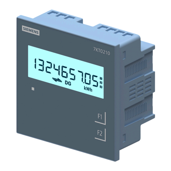
Discrete panel meter, 3 phase energy meter
Hide thumbs
Also See for 7KT:
- Manual (22 pages) ,
- Operating instructions manual (12 pages) ,
- Assembly instruction (5 pages)

Related Manuals for Siemens 7KT


Summary of Contents for Siemens 7KT
- Page 1 SMART 7KT0210 Manual MANUAL SMART 7KT Discrete Panel Meter 7KT0210 (3 phase energy meter) SMART 7KT power monitoring devices...
- Page 2 SMART 7KT0210 Manual Index SMART 7KT Introduction Discrete Panel Meter Safety precautions 7KT0210 (3 phase energy meter) Technical specification Installation Connection Configuration Manual Communication Maintenance 05/2023 SME7KT021000...
-
Page 3: Purpose Of This Document
SMART 7KT0210 Manual Introduction 1.1 Purpose of this document This present manual describes the SMART 7KT multifunction meter. It is intended for the use of: • Planners • Plant operators • Commissioning engineers • Service and maintenance personnel 1.2 Required basic knowledge A general knowledge of the field of electrical engineering is required to understand this manual. Knowledge of the relevant safety regulations and standards is required for installing and connecting the device. 1.3 Components of the product... -
Page 4: Safety Precautions
1. Read complete instructions prior to installation and operation of the unit. 2. Risk of electric shock. 3. The equipment in its installed state must not come in close proximity to any heating sources, oils, steam, caustic vapors or other unwanted process by products. Security information In order to protect plants, systems, machines, and network against cyber threats it is necessary to implement and continuously maintain a holistic state of the art industrial security concept. Siemens product and solutions constitute one element of such concept. For more information about industrial security please visit https:/www.siemens.com/industrial security... -
Page 5: Technical Specification
SMART 7KT0210 Manual Technical specification 7KT0210(3 Phase Energy Class 1) Power Monitoring Device Panel instrument for std electrical values Protocol: Modbus RTU, Single line LCD Display Vaux: 95V to 240V AC x/1 or 5 A, Class 1 Measurements measuring procedure • for voltage measurement True RMS • for current measurement True RMS type of measured value detection complete voltage curve Sinusoidal or distorted measurable line frequency • initial value 45 Hz • full-scale value 65 Hz operating mode for measured value detection automatic line frequency detection Supply voltage design of the power supply SMPS power supply type of voltage of the supply voltage Degree of protection class... - Page 6 • maximum 55 °C ambient temperature during storage • minimum -20 °C • maximum 75 °C relative humidity at 25 °C without condensation during operation maximum installation altitude at height above sea level maximum 2 000 m degree of pollution IEC Standards Certifications SMART 7KT multifunction meter conforms to IEC Description Standard Accuracy IEC 61557-12; standards, IPC electronics assembly standard and RoHS IEC 62053-21 | Active Energy EMC requirements IEC 61326-1 Degree of protection test (IP) IEC 60529 Safety requirements IEC 61010-1 and IEC 61010-2-030...
-
Page 7: Installation
SMART 7KT0210 Manual Assembly Installation For installing the meter Prepare the panel cutout with proper dimensions as shown below. OUTLINE PANEL CUTOUT FRONT PANEL DESCRIPTION Dimensions (in mm) Dimensions (in mm) -
Page 8: Wiring Guidelines
SMART 7KT0210 Manual Installation Guidelines 1. This equipment, being built-in-type, normally becomes a part of main control panel and in such case the terminals do not remain accessible to the end user after installation and internal wiring. 2. Conductors must not come in contact with the internal circuitry of the equipment or else it may lead to a safety hazard that may in turn endanger life or cause electrical shock to the operator. 3. Circuit breaker or mains switch must be installed between power source and supply terminals to facilitate power ‘ON’ or ‘OFF’ function. However this switch or breaker must be installed in a convenient position normally accessible to the operator. 4. Before disconnecting the secondary of the external current transformer from the equipment, make sure that the current transformer is short circuited to avoid risk of electrical shock and injury. 5. The equipment shall not be installed in environmental conditions other than those mentioned in this manual. 6. The equipment does not have a built-in-type fuse. Installation of external fuse of 0.5 A, Class Gg type for electrical circuitry is highly recommended. 7. Remove the scratch-guard from the meter display during commissioning of the panel. -
Page 9: Typical Wiring Diagram
SMART 7KT0210 Manual Connection Typical Wiring Diagram 3 Phase - 4 Wire 2 Phase - 3 Wire 3 Ø - 4 Wire, 3 CT’s and 3 PT’s 2 Ø - 3 Wire, 2 CT’s and 2 PT’s Network selection: 3P4W Network selection: 3P4W 3 Phase - 4 Wire (commonly used) 3 Phase - 3 Wire 3 Ø - 4 Wire, 3 CT’s 3 Ø - 3 Wire, 2 CT’s and 2 PT’s Network selection: 3P4W Network selection: 3P3W... -
Page 10: Terminal Connections
SMART 7KT0210 Manual Typical Wiring Diagram (Continued) 1 Phase - 2 Wire 1 Ø - 2 Wire, 1 CT Network selection: 1P2W Note: 1. # All fuse type: 0.5A, Class gG. 2. Grounding of current transformer is optional*. Terminal Connections RS485 24V DC * The transformers must always be connected and therefore always grounded the secondary side according to the applicable regulations. - Page 11 SMART 7KT0210 Manual Configuration There are two dedicated keys “F1” and “F2”. Keys have multiple assignments. Function assignments and key labelling change according to the context of operator input. For reading serial number Touch F1 key for 3 sec. to display 8-digit serial number only for 5 sec. Eg.: For serial number 11220002, the display will be: 11220002 Automatic / manual mode Auto / Manual mode can be set in configuration setting. By default, unit operates in automatic mode. In automatic mode online pages scroll automatically at the rate of 5 seconds per page. In automatic mode when any key is pressed, unit temporarily switches to manual mode and the appropriate page is displayed. If any key is not pressed for 5 sec, unit resumes automatic mode. In manual mode, unit shows the last set page after power on. Password to start configuration When the meter is set to configuration mode by touching keys F1 + F2, the password page will display which shows the password 0000.
- Page 12 SMART 7KT0210 Manual Parameterization with function keys Factory Sequence Function Range or Selection Setting Password 0000 to 9998 1000 Change password No / Yes New password 0000 to 9998 1000 Network selection 3P4W / 3P3W / 1P2W-R/ 1P2W-Y/ 1P2W-B 3P4W CT secondary 1 OR 5 CT primary 5 to 10000 , If CT SEC is 5A 1 to 10000, If CT SEC is 1A PT secondary 100 to 500 PT primary 100 to 500K Slave ID 1 to 255 Baud Rate 300, 600, 1200, 2400, 4800, 9600, 19200 9600...
- Page 13 SMART 7KT0210 Manual Reading of parameters Reading of parameters_1st source (Main source) Online Page Online Page Online Page Touch Key Touch Key Touch Key Description Description Description 3P4W 3P3W 1P2W-2nd After Power – Displays 1st After Power – Displays 1st- After Power –...
- Page 14 SMART 7KT0210 Manual Reading of parameters (Continued) Online Page Online Page Online Page Touch Key Touch Key Touch Key Description Description Description 3P4W 3P3W 1P2W-2nd Touch F2 Displays Touch F1 – Displays total 3rd time average of all Key 9th time Apparent 3 phase power energy of factor three phase...
- Page 15 SMART 7KT0210 Manual Reading of parameters (Continued) Online Page Online Page Online Page Touch Key Touch Key Touch Key Description Description Description 3P4W 3P3W 1P2W-2nd Touch F2 Displays EXP 4th time active energy of 2nd phase Touch F2 Displays EXP 5th time active energy of 3rd phase Touch F2 Displays total...
- Page 16 SMART 7KT0210 Manual Reading of parameters (Continued) Reading of parameters_2nd source (e.g. DG) Online Page Online Page Online Page Touch Key Touch Key Touch Key Description Description Description 3P4W (DG) 3P3W (DG) 1P2W-1st (DG) After Power – Displays 1st After Power –...
- Page 17 SMART 7KT0210 Manual Reading of parameters (Continued) Online Page Online Page Online Page Touch Key Touch Key Touch Key Description Description Description 3P4W (DG) 3P3W (DG) 1P2W-1st (DG) Touch F2 Displays 3rd Touch F2 Displays total 2nd time phase power 1st time active energy factor...
- Page 18 SMART 7KT0210 Manual Reading of parameters (Continued) Online Page Online Page Online Page Touch Key Touch Key Touch Key Description Description Description 3P4W (DG) 3P3W (DG) 1P2W-1st (DG) Touch F2 Displays total 1st time reactive energy (IMP & EXP) DG Touch F1 –...
- Page 19 SMART 7KT0210 Manual Communication Protocol and interface Connection diagram for communication Protocol: Modbus RTU Interface: Integrated RS485 interface Communication parameters Communication address 1 to 255 Transmission mode Half duplex Data types Float and Integer Transmission distance 500m maximum Transmission Speed 300, 600, 1200, 2400, 4800, 9600, 19200 (in bps) Parity None, Odd, Even Stop bits 1 or 2 Response Time 100ms Max & Independent, at Baud rate...
- Page 20 SMART 7KT0210 Manual Modbus register addresses list (Continued) Address HEX Address Parameter Address HEX Address Parameter 30072 0x48 Apparent power max demand 30148 0x94 Total Net kVArh(DG) 30082 0x50 On hour 30150 0x96 Total Net kWh(MAIN +DG) 30144 0x90 Total Net kWh(DG) 30152 0x98 Total Net kVAh(MAINs +DG) 30146 0x92 Total Net kVAh(DG)
-
Page 21: Maintenance
Maintenance Guidelines • The equipment should be cleaned regularly to avoid blockage of ventilating parts. • Clean the equipment with a clean dry or damp cloth. Do not use any cleaning agent other than water. Disposal and recycling Dispose of or recycle the module in accordance with the applicable laws and regulations in your country. - Page 22 These instructions do not purport to cover all details or variations in Siemens. Any statements contained herein do not create new warranties equipment, or to provide for every possible contingency in connection or modify the existing warranty. with installation, operation, or maintenance. Should additional Trademarks - Unless otherwise noted, all names identified by ® are information be desired, please contact the local Siemens sales office. The registered trademarks of Siemens AG or Siemens Industry, Inc. The contents of this instruction manual shall not become part of or modify remaining trademarks in this publication may be trademarks whose use any prior or existing agreement, commitment, or relationship. The...
Need help?
Do you have a question about the 7KT and is the answer not in the manual?
Questions and answers