
Related Manuals for Siemens 7KG85 Series


Summary of Contents for Siemens 7KG85 Series
- Page 1 Multifunktionsmessgerät und Power Quality-Schreiber SICAM P850/P855 7KG85xx Produktinformation E50417-B1050-C482-A3...
- Page 2 Verwendung innerhalb bestimmter Spannungsgrenzen (Nie- derspannungsrichtlinie 2006/95/EG). Diese Konformität ist das Ergebnis einer Prüfung, die durch die Siemens AG gemäß den Richtlinien in Übereinstimmung mit den Fachgrundnormen EN 61000-6-2 und EN 61000-6-4 für die EMV-Richtlinie und der Norm EN 61010-1 für die Nie- derspannungsrichtlinie durchgeführt worden ist.
-
Page 3: Table Of Contents
Inhaltsverzeichnis Vorwort Allgemeine Hinweise Hinweise zu Ihrer Sicherheit Verwendete Symbole Open Source Software Bestellinformationen Anwendung Aufbau Display und Softkeys 10 Montage und Inbetriebnahme 11 Anschlussarten 12 Messgrößen und Aufzeichnung 13 Schnittstellen 14 Abgleich 15 Batterieaustausch 16 LED-Meldungen 17 Fehlersuche, Instandsetzung, Reinigung 18 Lagerung und Transport 19 Technische Daten (Auswahl) SICAM P850/P855, Produktinformation... -
Page 4: Vorwort
Geschäftsbeziehung noch ändern sie diese ab. Alle Verpflichtungen der Siemens AG gehen aus den entsprechenden vertraglichen Vereinbarungen hervor. Die Siemens AG behält sich das Recht vor, dieses Dokument von Zeit zu Zeit zu ändern. Copyright Copyright © Siemens AG 2013. Alle Rechte vorbehal- ten. -
Page 5: Allgemeine Hinweise
Eingetragene Marken ® SICAM ist eine eingetragene Marke der Siemens AG. Jede nicht autorisierte Verwendung ist unzulässig. Alle anderen Beschreibungen in diesem Dokument bzw. in diesen Informationen können Marken enthal- ten, deren Verwendung durch Dritte für ihre eigenen Zwecke die Rechte des Eigentümers möglicherweise verletzen. -
Page 6: Hinweise Zu Ihrer Sicherheit
Unser Energy Customer Support Center unterstützt Sie rund um die Uhr. Tel.: +49 (1805) 24-8437 Fax: +49 (1805) 24-2471 Internet: http://www.powerquality.de E-Mail: support.ic@siemens.com Hinweise zu Ihrer Sicherheit Diese Produktinformation stellt kein vollständiges Ver- zeichnis aller für einen Betrieb des Betriebsmittels (Baugruppe, Gerät) erforderlichen Sicherheitsmaßnah- men dar, weil besondere Betriebsbedingungen weitere Maßnahmen erforderlich machen können. - Page 7 GEFAHR GEFAHR bedeutet, dass Tod oder schwere Verletzun- gen eintreten werden, wenn die angegebenen Maß- nahmen nicht getroffen werden. Beachten Sie alle Hinweise, um Tod oder schwere Verletzungen zu vermeiden. WARNUNG WARNUNG bedeutet, dass Tod oder schwere Verlet- zungen eintreten können, wenn die angegebenen Maßnahmen nicht getroffen werden.
- Page 8 Das Betriebsmittel (Gerät, Baugruppe) darf nur für die im Katalog und der technischen Beschreibung vorge- sehenen Einsatzfälle und nur in Verbindung mit von Siemens empfohlenen bzw. zugelassenen Fremdge- räten und -komponenten verwendet werden. Wird das Gerät nicht gemäß dieser Produktinformation benutzt, ist der vorgesehene Schutz beeinträchtigt.
-
Page 9: Verwendete Symbole
Auch nach Abtrennen der Versorgungsspannung können gefährliche Spannungen im Betriebsmittel vorhanden sein (Kondensatorspeicher). Betriebsmittel mit Stromwandlerkreisen dürfen nicht offen betrieben werden. Die in der Produktinformation und in den Handbü- chern genannten Grenzwerte dürfen nicht über- schritten werden; dies ist auch bei Prüfung und Inbetriebnahme zu beachten. -
Page 10: Open Source Software
Source Software gemäß den jeweiligen Open-Source- Software-Lizenzbedingungen zu nutzen. Bei Wider- sprüchen zwischen den Open-Source-Software- Lizenzbedingungen und den für das Produkt geltenden Siemens Lizenzbedingungen gelten in Bezug auf die Open Source Software die Open-Source-Software- Lizenzbedingungen vorrangig. Die Open Source Software wird unentgeltlich überlas- sen. -
Page 11: Bestellinformationen
Bestellinformationen Bestellschlüssel: Beschreibung Bestellnr. / MLFB Multifunktionsmessgerät und Power Quality-Schreiber 1 2 3 10 11 12 13 14 15 16 SICAM P850/P855 UL-zertifiziert Gerätetyp Abmessungen 96 mm x 96 mm x 100 mm 4 Eingänge für Wechselspannungsmessungen 3 Eingänge für Wechselstrommessungen 2 Binärausgänge Galvanisch isolierte Spannungsmesseingänge Web-Server für Parametrierung , Visualisierung und... -
Page 12: Anwendung
Anwendung SICAM P850/P855-Geräte erfassen in allen Span- nungsebenen der Energienetze Messgrößen gemäß der Norm IEC 61000-4-30. Die Messgrößen können über die Kommunikationsschnittstellen zu einem PC und zur Leittechnik ausgegeben oder auf einem optio- nalen Display angezeigt werden. Außerdem werden beim SICAM P855 Betriebs- und Power Quality-Mess- werte in parametrierbaren Zeitintervallen mit diversen Schreibern (z.B. -
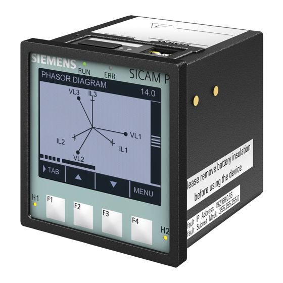
Page 13: Aufbau
Aufbau Die elektrischen Baugruppen des Gerätes sind in einem Kunststoffgehäuse mit den Maßen 96 mm x 96 mm x 100 mm (B x H x T) untergebracht. Typenschild 4 LEDs RJ45 mit 2 LEDs Batteriefach- deckel Display Softkeys F1 bis F4 LED H1 LEDs RUN und ERROR... - Page 14 identisch zu den LEDs auf der Displayseite. Am Batte- riefachdeckel befinden sich ein Beschriftungsfeld für die parametrierbaren LEDs H1, H2 und ERROR sowie ein Batteriesymbol mit der Darstellung der Batteriepo- larität. Ebenso ist auf der Oberseite das Typenschild aufgeklebt, das u. a. die wichtigsten Nenndaten des Gerätes enthält.
-
Page 15: Display Und Softkeys
Display und Softkeys Display Der Aufbau des Displays ist in Bild 9-1 dargestellt. Titel Spannung L-N MAX 230.00 V Datum/Zeit Anzeigebereich 231.00 V Datum/Zeit 229.00 V Datum/Zeit Softkey- 2.00 V Datum/Zeit Funktionen MENÜ Softkeys F1 - F4 Bild 9-1 Display und Softkeys In der oberen Zeile (Titel) ist die aktuelle Darstellung im Anzeigebereich benannt. -
Page 16: Montage Und Inbetriebnahme
Montage und Inbetriebnahme 10.1 Allgemeine Hinweise GEFAHR Gefahr durch hohe Berührungsspannungen Nichtbeachtung hat Tod oder schwere Körperver- letzung zur Folge. Beachten Sie im Folgenden alle Bedien- und Warn- hinweise. Vor Beginn der Montage des Gerätes ist die mitgelie- ferte Lithium-Batterie gemäß Kapitel 10.4 einzu- bauen. - Page 17 10.2 Einbau/Montage HINWEIS Ausreichender Schutz gegen hohe Berührungsspan- nungen ist nur bei korrekter Montage gewährleistet. Einbau des Gerätes in eine Schalttafel Schwenken Sie das mitgelieferte Befestigungsele- ment um den hinteren Kegel ein. Montageplatte Befestigungselement ≥ 1 mm, Stahl Bild 10-1 Schalttafeleinbau Stellen Sie das Befestigungselement waagerecht und schrauben Sie es mit einem Schraubendreher (0,6 mm x 4,5 mm) fest, bis die Rutschkupplung wirk-...
- Page 18 Hutschienenmontage gemäß EN 60750 Führung des Hutschienen- Clips Hutschienen-Clip Entriegelung Hutschiene Zugrichtung Bild 10-2 Hutschienenmontage 1. Ziehen Sie die Entriegelung am Hutschienen-Clip nach unten und halten Sie die Entriegelung in dieser Position fest. 2. Schieben Sie das Gerät mit der Führung des Hut- schienen-Clips auf eine Seite der Hutschiene.
- Page 19 10.3 Elektrischer Anschluss GEFAHR Gefahr durch hohe Berührungsspannungen Nichtbeachtung hat Tod oder schwere Körperver- letzungen zur Folge. Die Arbeiten dürfen nur von elektrotechnisch qualifi- ziertem Personal (siehe Vorwort) vorgenommen wer- den, das mit den Sicherheitsbestimmungen und Vorsichtsmaßnahmen vertraut ist und diese befolgt. Die Arbeiten dürfen Sie niemals beim Vorhandensein gefährlicher Spannungen durchführen.
- Page 20 Die Polarität und die Phasenzuordnung an den Messwandlern sind durch Sie zu überprüfen. Siemens empfiehlt, das Gerät mindestens 2 Stunden im Betriebsraum liegen zu lassen, bevor Sie es in Betrieb nehmen, um einen Temperaturausgleich zu schaffen und um Feuchtigkeit sowie Kondensation zu vermeiden.
- Page 21 1. Hebeln Sie mit einem geeigneten Werkzeug (z.B. Feinmechaniker-Schraubendreher 2,0 mm) den Batteriefachdeckel aus der Fassung. Batteriefach- deckel Polaritäts- angabe der Batterie Typenschild Bild 10-3 Geräteoberseite 2. Entnehmen Sie aus der Batteriefassung die ver- packte Batterie. 3. Entfernen Sie die Kunststofffolie von der Batterie. 4.
-
Page 22: Anschlussarten
10.5 Parametrierung HINWEIS Die Parametrierung ist im Gerätehandbuch, Bestell- nummer E50417-H1000-C482, beschrieben. Anschlussarten Die folgenden Eingangsbeschaltungen sind Beispiele. SICAM P850/P855 kann bis zu den maximal zulässi- gen Strom- und Spannungswerten (siehe Kapitel 19.1) auch ohne zwischengeschaltete Strom- oder Span- nungswandler angeschlossen werden. Erforderliche Spannungswandler können in Stern- oder Dreieckschaltung betrieben werden. - Page 23 11.1 Beispiel: Einphasennetz 10 A 11.2 Beispiel: 3-Leiternetz, gleiche Belastung 10 A 10 A 10 A ACHTUNG Die Sekundärspannung am Klemmenblock F (Voltage) darf AC 480 V (AC 347 V bei UL-Bedingungen) nicht über- schreiten. Es können Sachschäden entstehen. Achten Sie darauf, dass die maximal zulässige Span- nung Leiter - Erde (PE) nicht überschritten wird.
- Page 24 HINWEIS Die Verbindung PE-N nicht zwingend erforderlich. 11.3 Beispiel: 3-Leiternetz, beliebige Belastung 10 A 10 A 10 A ACHTUNG Die Sekundärspannung am Klemmenblock F (Voltage) darf AC 480 V (AC 347 V bei UL-Bedingungen) nicht über- schreiten. Es können Sachschäden entstehen. Achten Sie darauf, dass die maximal zulässige Span- nung Leiter - Erde (PE) nicht überschritten wird.
- Page 25 11.4 Beispiel: 4-Leiternetz, gleiche Belastung 10 A 11.5 Beispiel: 4-Leiternetz, beliebige Belastung für Niederspannungsnetze je 10 A SICAM P850/P855, Produktinformation E50417-B1050-C482-A3, Ausgabestand 03.2013...
- Page 26 11.6 Beispiel: 4-Leiternetz, beliebige Belastung für Hochspannungsnetze je 10 A HINWEIS Außer den in dieser Betriebsanleitung enthaltenen Schaltungsbeispielen sind im Gerätehandbuch SICAM P850/P855, Bestellnummer E50417-H1000- C482, weitere Anschlussbeispiele aufgeführt. SICAM P850/P855, Produktinformation E50417-B1050-C482-A3, Ausgabestand 03.2013...
-
Page 27: Messgrößen Und Aufzeichnung
Messgrößen und Aufzeichnung Angaben gemäß der Produktnormen IEC 62586-1, Klasse S und IEC 61557-12 sowie der Normen IEC 61000-4-30, Ed. 2, IEC 61000-4-7, IEC 61000-4-15 Messgrößen Messpfad Toleranz- grenzen Spannung U L1-N, L2-N, ±0,2 % L3-N Spannung U L1-L2, L2- ±0,2 % L3, L3-L1, Σ... - Page 28 Messgrößen Messpfad Toleranz- grenzen L1, L2, L3, Σ ±0,5 % Wirkenergie WP Bezug Wirkenergie WP Lieferung L1, L2, L3, Σ ±0,5 % Blindenergie WQ induktiv L1, L2, L3, Σ ±0,5 % Blindenergie WQ kapazitiv L1, L2, L3, Σ ±0,5 % L1, L2, L3, Σ...
-
Page 29: Schnittstellen
Schnittstellen Bild 13-1 Anschlüsse an der Klemmenseite Klemmen für Versorgungsspannung (H), Eingänge für Strommessung (E) und für Spannungsmessung (F) und Binärausgänge (G) auf der Klemmenseite: Leiterquerschnitt 2,5 mm² Leiterquerschnitt mit Aderendhülse 1,5 mm² mit Aderendhülse (Klemme F) 2,5 mm² Anzugsmoment 0,4 Nm bis 0,5 Nm RS485-Schnittstelle (J) auf der Klemmenseite: RS485-Kabel mit Steckverbinder (D-Sub) - Page 30 Anschlussbelegung Tabelle 13-1 Anschlussbelegung SICAM P850/P855 Anschluss Funktion Beschreibung Leiter 1, Eingang, => E: I Strommessung Leiter 1, Ausgang, <= E: I Strommessung Leiter 2, Eingang, => E: I Strommessung Leiter 2, Ausgang, <= E: I Strommessung Leiter 3, Eingang, =>...
-
Page 31: Abgleich
Anschluss Funktion Beschreibung Nullleiter der Netzspannung/ H: N / - negativeVersorgungsspg. Phase der Netzspannung/ H: L / + positive Versorgungsspannung RS485 Serielle Schnittstelle (wenn in Geräteversion vorhanden) Ethernet- Ethernet-Anschluss; auf der Schnittstelle Oberseite des Gehäuses Abgleich WARNUNG Warnung vor Unfällen bei Benutzung von ungeeig- netem Werkzeug Nichtbeachtung kann Tod oder schwere Körperver- letzung zur Folge haben. -
Page 32: Batterieaustausch
Batterieaustausch Wenn die Batterieladung zu gering ist, ist ein Batterie- austausch erforderlich (vollständige Entladung vermei- den). In diesem Fall wird die Betriebsmeldung „Batteriefehler“ erzeugt. Diese Meldung können Sie auch auf eine der 3 LEDs H1/H2/ERROR parametrie- ren oder auf einen Binärausgang rangieren (siehe Gerätehandbuch, Bestellnummer E50417-H1000- C482). - Page 33 Bei Ausgabe der Meldung „Batteriefehler“ wechseln Sie die Batterie wie folgt aus: 1. Hebeln Sie mit einem geeigneten Werkzeug (z.B. Feinmechaniker-Schraubendreher 2,0 mm) den Batteriefachdeckel aus der Fassung. Batteriefach- deckel Bild 15-1 Entfernen des Batteriefachdeckels 2. Ziehen Sie mit einem geeigneten nichtleitenden Werkzeug (z.B.
-
Page 34: Led-Meldungen
der neben dem Batteriefachdeckel aufgedruckten Polarität in die Batteriefassung ein. 6. Drücken Sie den Batteriefachdeckel in richtiger Ein- baulage wieder in das Gehäuse. HINWEISE zur Batterie-Entsorgung Die im Gerät befindliche Batterie enthält Lithium und darf nur durch Fachpersonal ausgewechselt und durch entsprechende Recyclingbetriebe entsorgt werden. - Page 35 Bedeutung der LEDs LED (grün, rot, gelb): ein LED (grün, rot, gelb): blinkt LEDs H1/H2/ERROR: gemäß Parametrierung LED: aus LED Speed (gelb): aus/ein: 10/100 MBit/s) LED Link/Activity (grün) leuchtet: Ethernet Link vorhanden blinkt: Ethernet Link vorhanden, Datentransfer aus: keine Ethernet-Partner angeschlossen LEDs Bedeutung Gerät ausgeschaltet...
- Page 36 LEDs Bedeutung Das Boot-Programm ist gestartet, nachdem ERROR die Softkey F4 während des Einschaltens gedrückt wurde (Reset Default-IP-Adresse). ERROR DHCP aktiv (H1 schaltet aus nach Empfang der IP-Adresse über DHCP) ERROR Default-IP-Adresse wurde mittels Drücken der Softkey F4 übernommen. Boot-Programm gestartet; es existiert keine ERROR Prozessapplikation.
- Page 37 LEDs Bedeutung Boot-Programm gestartet, ERROR Prozessapplikation wird geladen. Doppelte IP-Adresse wurde erkannt. ERROR Prozessapplikation Normaler Betrieb ERROR Nutzung der parametrierten IP-Adresse oder IP-Adresse über DHCP bezogen. DHCP (LED RUN (grün) leuchtet, nachdem ERROR ERROR IP-Adresse von DHCP-Server empfangen). Default-IP-Adresse wurde mittels Drücken ERROR der Softkey F4 übernommen.
-
Page 38: Fehlersuche, Instandsetzung, Reinigung
-40 °C bis +70 °C. Die relative Luft- feuchte darf weder zur Kondenswasser- noch zur Eis- bildung führen. Siemens empfiehlt Ihnen, bei der Lagerung einen ein- geschränkten Temperaturbereich zwischen +10 °C und +35 °C einzuhalten, um einer vorzeitigen Alterung der eingesetzten Elektrolytkondensatoren vorzubeugen. -
Page 39: Technische Daten (Auswahl)
Die Lithium-Batterien unserer Geräte erfüllen die inter- nationalen Voraussetzungen der Gefahrgutvorschriften für die verschiedenen Verkehrsträger (Sonderbestim- mung 188 aus den UN-Empfehlungen für den Trans- port gefährlicher Güter, Sonderbestimmung A45 der IATA-Gefahrgutvorschrift und den technischen Anlei- tungen der ICAO). Dies gilt nur für die Originalbatterie oder Original-Ersatzbatterien. - Page 40 Eingangswiderstände L1, L2, L3 zu N 6,0 MΩ L1 - L2, L2 - L3, L3 - L1 6,0 MΩ Leistungsaufnahme pro Eingang 38 mW bei U = 400 V nenn Maximale Eingangsspannung 1,2 x Nennein- gangsspannung Eingänge für Wechselstrommessungen Nenneingangsstrombereiche Max.
- Page 41 19.3 Isolationsprüfung nach IEC 61010-1 und IEC 61010-2-030 Ein-/ Isolierung Nenn- ISO-Prüf- Kate- Ausgänge spannung spannung gorie Strom- verstärkt 150 V AC 2,3 kV Kat. III messeingänge Spannungs- verstärkt 480 V Stoßspan- Kat. III messeingänge nung 9,76 kV Versorgungs- verstärkt 300 V DC 3,125 kV Kat.
- Page 42 19.5 Ethernet Busprotokoll IEC 61850 Server Modbus TCP Übertragungsrate 100 MBit/s Kommunikationsprotokoll IEEE 802.3 Anschluss 100Base-T (RJ45) 100 Ω bis 150 Ω STP, CAT5 Kabel für 100Base-T Max. Kabellänge 100Base-T100 m Spannungsfestigkeit DC 700 V 19.6 Seriell, RS485-Schnittstelle (optional) Verbindung 9-poliger D-SUB-Steckverbinder Busprotokoll Modbus RTU (optional) Baud-Rate...
- Page 43 19.8 Batterie Typen PANASONIC CR2032 VARTA 6032 101 501 Spannung Kapazität 230 mAh Typische Lebensdauer bei ständig angelegter Versorgungsspannung 10 Jahre bei sporadisch unterbrochener Versorgungsspannung summiert 2 Monate in bis zu 10 Jahren 19.9 Umgebungsbedingungen Betriebstemperatur (kontinuierl.) -25 °C bis +55 °C Geräte mit Display: Das Display ist bei Temperaturen <...
- Page 44 19.12 Masse und Maße Masse - Gerät ohne Display ca. 0,49 kg - Gerät mit Display, ohne Display ca. 0,52 kg - Gerät mit Display und Tür ca. 0,6 kg Abmessungen (B x H x T) 96 mm x 96 mm x 100 mm 102,9 95,5...
- Page 45 Power Monitoring Device and Power Quality Recorder SICAM P850/P855 7KG85xx Product Information E50417-B1050-C482-A3...
- Page 46 Directive 2006/95/EC). This conformity has been established by means of tests con- ducted by Siemens AG in accordance of the Council Direc- tive in agreement with the generic standards EN 61000-6-2 and EN 61000-6-4 for the EMC directives, and with the stan- dard EN 61010-1 for the low-voltage directive.
- Page 47 Contents Preface General Information Information for Your Safety Used Symbols Open Source Software Ordering Information Application Design Display and Softkeys 10 Mounting and Commissioning 11 Connection Types 12 Measurands and Recording 13 Interfaces 14 Calibration 15 Replacing the Battery 16 LED Indications 17 Troubleshooting, Repair, Cleaning 18 Storage and Transport 19 Technical Data (Selection)
-
Page 48: Preface
Although Siemens AG has made best efforts to keep the document as precise and up-to-date as possible, Siemens AG shall not assume any liability for defects and damage which result through use of the information contained herein. -
Page 49: General Information
Registered Trademarks ® SICAM is a registered trademark of Siemens AG. An unauthorized use is illegal. All other designations in this document can be trademarks whose use by third parties for their own purposes can infringe the rights of the owner. -
Page 50: Information For Your Safety
Chapter 1. If you have any questions about the device, please con- tact our Siemens sales partner responsible in your region. Our Energy Customer Support Center is available to you twenty-four hours a day. - Page 51 DANGER DANGER means that death or severe injury will occur if the appropriate safety measures are not taken. Follow all advice instructions to prevent death or severe injury. WARNING WARNING means that death or severe injury can occur if the appropriate safety measures are not taken. Follow all advice instructions to prevent death or severe injury.
- Page 52 Technical Description. If it is used together with third-party devices and components, these must be recommended or approved by Siemens. If the device is not used in accordance with this product information, the scheduled protection is impaired.
-
Page 53: Used Symbols
be operated openly. The limiting values indicated in the product informa- tion and the manuals must not be exceeded; this also refers to testing and commissioning. Used Symbols Table 4-1 Used Symbols Symbol Description Direct current IEC 60417-5031 Alternating current IEC 60417-5032 Direct and alternating current IEC 60417-5033... -
Page 54: Open Source Software
License Conditions provide for it you can order the source code of the Open Source Software from your Siemens sales contact - against payment of the ship- ping and handling charges - for a period of at least 3 years since purchase of the Product. We are liable for... -
Page 55: Ordering Information
Ordering Information Ordering code: Description Order No. / MLFB Power Monitoring Device and Power Quality Recorder 1 2 3 10 11 12 13 14 15 16 SICAM P850/P855 UL Certification Device type Dimensions 96 mm x 96 mm x 100 mm 4 Inputs for AC voltage measurements 3 Inputs for AC current measurements 2 Binary outputs... -
Page 56: Application
Application SICAM P850/P855 devices acquire measurands at all voltage levels of power systems according to the IEC 61000-4-30 standard. The communication inter- faces enable the measurands to be forwarded to a PC and to the control center or to be displayed on an optional display. -
Page 57: Design
Design The electrical modules of the device are installed in an insulated housing with the dimensions 96 mm x 96 mm x 100 mm (W x H x D). Type plate 4 LEDs Cover of RJ45 with battery 2 LEDs compartment Display Softkeys... - Page 58 identical to the LEDs on the display side. At the cover of the battery compartment there is a labelling strip for the configurable LEDs H1, H2 and ERROR and a bat- tery symbol that indicates the polarity. The type plate is also located on the top side and provides among other information the most important rated data of the device.
-
Page 59: Display And Softkeys
Display and Softkeys Display The structure of the display is shown in Figure 9-1. Title Voltage ph-n MAX 230.00 V Date/Time 231.00 V Date/Time Display area 229.00 V Date/Time Softkey 2.00 V Date/Time functions MENU Softkeys Figure 9-1 Display and Softkeys The top line (title) shows the name of the current dis- play in the display area. -
Page 60: Mounting And Commissioning
Mounting and Commissioning 10.1 General Information DANGER Danger due to high voltages Non-observance will lead to death or serious injury. Please read and observe all instructions and warn- ings contained in this document. Before installing the device, insert the supplied Lithium battery as described in Chapter 10.4. - Page 61 10.2 Flush-mounting/Assembly NOTE To provide sufficient protection against high contact voltages, install the device correctly. Flash-mounting of the device into a panel Swing the mounting element (provided with the device) over the rear cone. Mounting plate Mounting element ≥ 1 mm, steel Figure 10-1 Panel Flush Mounting Move the mounting element to the position.
- Page 62 DIN-rail assembly according to EN 60750 Guiding of the snap-on clip Snap-on clip DIN rail Release device Pulling direction Figure 10-2 DIN-Rail Assembly 1. Pull down the release device at the snap-on clip and hold it in this position. 2. Slide the device with the guiding of the snap-on clip on to one side of the DIN rail.
- Page 63 UL-certification conditions Field Wires of Control Circuits shall be separated from other circuits with respect to the end use requirements! 10.3 Electrical Connection DANGER Danger due to high voltages Non-observance will lead to death or serious injury. Work may only be carried out by trained personnel (see Preface) who are familiar with and observe the safety requirements and precautions.
- Page 64 connections are made properly. Connect the protective conductor terminal H the protective conductor of the switch panel or of the control cabinet. The secondary connections of interconnected current transformers must be short-circuited at these before you disconnect the power supply leads to the device. Voltage measuring inputs: In the case of a direct connection and transformer connection, the device has to be safeguarded with a listed 10 A backup fuse...
- Page 65 1. Lever the cover of the battery compartment out of the socket with a suitable tool (e.g. precision engineer screwdriver 2.0 mm). Cover of battery compartment Polarity of the battery Type plate Figure 10-3 Device Top Side 2. Remove the battery. 3.
-
Page 66: Connection Types
10.5 Setting the Parameters NOTE The parameterization is described in the device manual, order number E50417-H1040-C482. Connection Types The following input wiring diagrams are examples. Up to the maximum allowable current and voltage values (see Chapter 19.1) SICAM P850/P855 can also be connected without interconnected current and voltage transformers. - Page 67 11.1 Example: 1-phase System 10 A 11.2 Example: 3-wire System, Balanced 10 A 10 A 10 A NOTICE The secondary voltage on terminal block F (voltage) must not exceed AC 480 V (AC 347 V for UL condi- tions). This could cause material damage. Please make sure that the maximum permissible voltage on conductor - ground (PE) is not exceeded.
- Page 68 NOTE The electrical connection PE-N is not mandatory. 11.3 Example: 3-wire System, Unbalanced 10 A 10 A 10 A NOTICE The secondary voltage on terminal block F (voltage) must not exceed AC 480 V (AC 347 V for UL condi- tions This could cause material damage.
- Page 69 11.4 Example: 4-wire System, Balanced 10 A 11.5 Example: 4-wire System, Unbalanced for low-voltage power systems resp. 10 A SICAM P850/P855 7KG85xx, Product Information E50417-B1050-C482-A3, Edition 03.2013...
- Page 70 11.6 Example: 4-wire System, Unbalanced for high-voltage power systems resp. 10 A NOTE The SICAM P850/P855 device manual, order number E50417-H1040-C482, provides more circuit examples in addition to the ones shown in these operating instructions. SICAM P850/P855 7KG85xx, Product Information E50417-B1050-C482-A3, Edition 03.2013...
-
Page 71: Measurands And Recording
Measurands and Recording Specifications acc. to product standards IEC 62586-1, Class S and IEC 61557-12, and according to standards IEC 61000-4-30, Ed. 2, IEC 61000-4-7, IEC 61000-4-15 Measurands Circuit Tolerance limits Voltage V a-N, b-N, c-N ±0.2 % ph-N Voltage V a-b, b-c, ±0.2 % ph-ph... - Page 72 Measurands Circuit Tolerance limits a, b, c, Σ Active energy WP supply ±0.5 % a, b, c, Σ Reactive energy WQ ind. ±0.5 % a, b, c, Σ Reactive energy WQ cap. ±0.5 % a, b, c, Σ Apparent energy WS ±0.5 % THD voltage THD V a-N, b-N, c-N ±0.5 %...
-
Page 73: Interfaces
Interfaces Figure 13-1 Terminals on the Terminal Side Terminals for supply voltage (H), inputs for current measurement (E), inputs for voltage measurement (F), binary outputs (G) on the terminal side: Conductor cross-section 2.5 mm² (AWG 14) with bootlace ferrule 1.5 mm² (AWG 16) with bootlace ferrule (term. - Page 74 Terminal assignment Table 13-1 Terminal assignment SICAM P850/P855 Connection Function Description Conductor a, input, => E: I current measurement Conductor a, output, <= E: I current measurement Conductor b, input, => E: I current measurement Conductor b, output, <= E: I current measurement Conductor c, input, =>...
-
Page 75: Calibration
Connection Function Description Neutral of the mains voltage/ H: N / - negative supply voltage ph/+ Phase of the mains voltage/ H: L / + Positive supply voltage RS485 Serial interface (if available in the device version) Ethernet Ethernet connection; on the top interface side of the housing Calibration... -
Page 76: Replacing The Battery
Replacing the Battery Replace the batteries if the battery charge is too low (avoid full discharge). In this case the "Battery Failure" operation indication is generated. This message can also be parameterized on one of the 3 LEDs H1/H2/ ERROR or switched to one of the binary outputs (see Device Manual SICAM P850/P855, order number E50417-H1040-C482). - Page 77 When the "Battery Failure" indication is displayed, replace the battery as follows: 1. Lever the cover of the battery compartment out of the socket with a suitable tool (e.g. precision engi- neer screwdriver 2.0 mm). Cover of battery compartment Figure 15-1 Removing the Cover of the Battery Compartment 2.
-
Page 78: Led Indications
battery compartment. 6. Press the cover of the battery compartment back into the housing and make sure it is in the correct position. NOTES on battery disposal The battery used in this device contains lithium. It may only be replaced by qualified personnel and disposed of by authorized recycling companies. - Page 79 Meaning of the LEDs LED (green, red, yellow): on LED (green, red, yellow): flashes LEDs H1/H2/ERROR: acc. to parameter- ization LED: off LED Speed (yellow): off/on: 10/100 Mbit/s) LED Link/Activity (green) lit: Ethernet link is up flashes: Ethernet link is up, data transfer off: no Ethernet partners connected LEDs Meaning...
- Page 80 LEDs Meaning The Boot program was started after ERROR pressing softkey F4 during startup of the device (reset of default IP address). ERROR DHCP active (H1 switches off after reception of the IP address via DHCP) ERROR The default IP address was applied by pressing softkey F4.
- Page 81 LEDs Meaning Boot loader started, process application is ERROR being loaded. Double IP address detected. ERROR Process Application Normal operation ERROR IP address as configured or obtained by DHCP. DHCP (LED RUN (green) is lit after the IP ERROR ERROR address was received by the DHCP server).
-
Page 82: Troubleshooting, Repair, Cleaning
Furthermore, hazardous voltages can lead to lethal injuries when the work is performed improperly. If you suspect that the device has a defect, Siemens recommends to send the entire device back to the manufacturer. If possible, use the original transport packaging or an equivalent packaging. -
Page 83: Technical Data (Selection)
The Lithium-batteries in our equipment are subject to Special Provision 188 of the UN Recommendations on the Transport of Dangerous Goods Model Regulations and Special Provision A45 of the IATA Dangerous Goods Regulation and the ICAO Technical Instructions. This is only valid for the original battery or original spare batteries. - Page 84 Input impedances a, b, c to N 6.0 MΩ a - b, b - c, c - a 6.0 MΩ Power consumption per input 38 mW at V = 400 V rated Maximum input voltage 1.2 x rated input voltage Inputs for alternating current measurements Rated input current ranges Maximum input voltage...
- Page 85 19.3 Insulation test according to IEC 61010-1 and IEC 61010-2-030 Inputs/outputs Insulation Rated Insulation Category voltage test voltage Current Reinforced 150 V AC 2.3 kV Cat. III measuring inputs Voltage Reinforced 480 V Surge voltage Cat. III measuring inputs 9.76 kV Supply voltage Reinforced 300 V...
- Page 86 19.5 Ethernet Bus protocol IEC 61850 server Modbus TCP Transmission rate 100 Mbit/s Communication protocol IEEE 802.3 Connection 100Base-T (RJ45) 100 Ω to 150 Ω STP, CAT5 Cable for 100Base-T Max. cable length 100Base-T 100 m Voltage strength DC 700 V 19.6 Serial, RS485 Interface (optional) Connection...
- Page 87 19.8 Battery Types PANASONIC CR2032 VARTA 6032 101 501 Voltage Capacity 230 mAh Typical life time at permanently available 10 years power supply at not permanently available in sum 2 months in up to power supply 10 years 19.9 Environmental Conditiones Operating temperature (cont.) -25 °C to +55 °C -13 °F to +131 °F...
- Page 88 19.12 Mass and Dimensions Mass - Device without display about 0.49 kg - Device with display, without door about 0.52 kg - Device with display and door about 0.6 kg Dimensions (W x H x D) 96 mm x 96 mm x 100 mm 3.78 inches x 3.78 inches x 3.94 inches 102.9 (4.05)
Need help?
Do you have a question about the 7KG85 Series and is the answer not in the manual?
Questions and answers