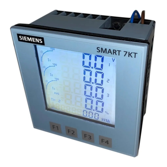
Siemens SMART 7KT Manual
Multifunction meter
Hide thumbs
Also See for SMART 7KT:
- Manual (23 pages) ,
- Operating instructions manual (12 pages) ,
- Assembly instruction (5 pages)


Need help?
Do you have a question about the SMART 7KT and is the answer not in the manual?
Questions and answers