Siemens SMART 7KT Operating Instructions Manual
Hide thumbs
Also See for SMART 7KT:
- Manual (22 pages) ,
- Assembly instruction (5 pages) ,
- Manual (18 pages)
Table of Contents
Advertisement
Quick Links
s
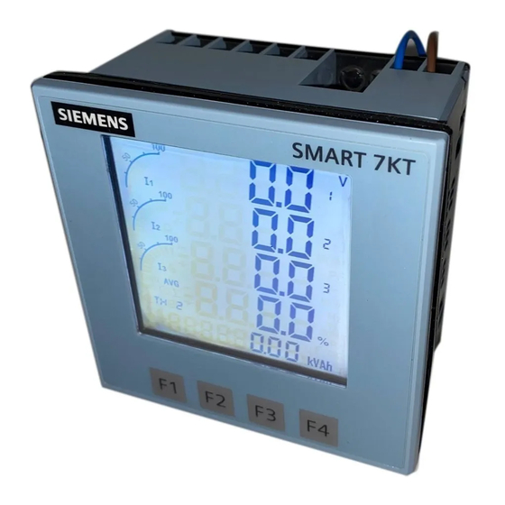
Multi-function Meter
SMART 7KT
7KT0310
Technical Specifi cation
DISPLAY
Large backlit Liquid Crystal display
4 Lines with 4 digits each to show measured values
5th Line with 8 digits to show energy values
Bar graph for current indication
LCD INDICATIONS
I
- Integration of energy
PRG
- Unit is in confi guration menu
- Communication in progress
MAX DMD - Maximum and Minimum Demand Power
WIRING INPUT
3 Ø - 4 wire, 3 Ø - 3 wire,
RATED INPUT VOLTAGE
11 to 300V AC (L-N); 19 to 519V AC (L-L);
Installation Category III (600V)
FREQUENCY RANGE: 45-65 Hz
RATED INPUT CURRENT
Nominal 1A / 5A AC (Min-11mA , Max-6A for 5A)
BURDEN: 0.5 VA@5A per phase
CURRENT TRANSFORMER TYPE: Measurement C.T, FS 10
CT PRIMARY
1A / 5A to 10,000A (Programmable for any Value)
• 1A to 10,000A when CT secondary is 1
• 5A to 10,000A when CT secondary is 5
CT SECONDARY: 1A or 5A (Programmable)
PT PRIMARY: 100V to 500kV (Programmable for any value)
PT SECONDARY
100V to 500V AC (L-L)(Programmable for any value)
DISPLAY UPDATE TIME
1 sec. for all parameters
Operating Instructions
Please read and understand these instructions before installing,
operating, or maintaining the equipment.
DANGER
Hazardous voltage. Will cause death or serious
injury. Turn off and lock out all power supply to
this device before working on this device.
Replace all covers before power supplying this
device is turned on.
DISPLAY SCROLLING
Automatic or Manual (Programmable)
POWER CONSUMPTION
Less than 8VA
ENVIRONMENTAL CONDITIONS
- Indoor use
- Altitude of up to 2000 meters
- Pollution degree II
Temperature : Operating : -10°C to 55°C
Storage
Humidity
: Up to 85% non-condensing
PROTECTION CLASS: II
IP 65 (Front Panel Door); IP 20 (Rear Side)
OVERVOLTAGE CATEGORY : III
MOUNTING: Panel mounting
WEIGHT:
360gms
ORDER CODE INFORMATION
Product
7KT0310
95V to 240V AC, ±10%, 50/60Hz (±5%)
SERIAL COMMUNICATION
Interface standard and protocol
Communication address
Transmission mode
Data types
Transmission distance
Transmission Speed
Parity
Stop bits
Response Time
: -20°C to 75°C
Supply
RS485 and MODBUS RTU
1 to 255
Half duplex
Float and Integer
500m maximum
300, 600, 1200, 2400, 4800, 9600,
19200 (in bps)
None, Odd, Even
1 or 2
100ms Max & Independent, at Baud
rate
Advertisement
Table of Contents

Related Manuals for Siemens SMART 7KT


Summary of Contents for Siemens SMART 7KT
- Page 1 Operating Instructions Multi-function Meter SMART 7KT 7KT0310 Please read and understand these instructions before installing, operating, or maintaining the equipment. DANGER Hazardous voltage. Will cause death or serious injury. Turn off and lock out all power supply to this device before working on this device.
-
Page 2: Required Tools
Technical Specifi cation (Continued) ACCURACY, as per IEC 62053-21 Measurement Accuracy Measurement Accuracy Voltage V ± 0.5% of Full scale (300V AC) MAX / MIN Active Voltage V ± Full scale 0.5% MAX / MIN Reactive Current ± 0.5% of Full scale (6A) Frequency ±... -
Page 3: Mounting Distance
For demounting the meter Pull the arm of the sliding clamps in outward Dis-assemble the snap fi tted base clamps from Push the meter from back side out of the panel direction (opposite to meter) and drag the the meter using a screw-driver window and remove the gasket from the meter sliding clamps away from the panel. -
Page 4: Wiring Guidelines
Wiring Guidelines 1. To prevent the risk of electric shock, power supply to 5. Layout of connecting cables shall be away from any the equipment must be kept OFF while doing the wiring internal EMI source. arrangement. 6. Cable used for connection to power source, must have a 2. - Page 5 Confi guration There are 4 dedicated keys labelled as F1, F2, F3, F4. Use ONLINE PAGE DESCRIPTION these 4 keys to read meter parameters. Simply press these PRESS keys to read the parameters. Press The fi rst screen: Displays import active energy of fi rst phase. “F4”...
- Page 6 Confi guration (Continued) There are 4 dedicated keys F1, F2, F3, F4. use these 4 keys to Confi g. Factory Function Range or Selection enter into confi guration menu / change setting. page Setting Note: The settings should be done by a professional, after 16.14 Page sequence 14 1 to 22...
- Page 7 MODBUS REGISTER ADDRESSES LIST Readable Parameters: [Length (Register): 2; Data Structure: Float] Address Hex Address Parameter Address Hex Address Parameter 30000 0x00 Voltage V1N 30684 0x2AC Serial no. (Data Structure: Hex) 30002 0x02 Voltage V2N 30692 0x2B4 MAX I1 Demand 30004 0x04 Voltage V3N...
- Page 8 MODBUS REGISTER ADDRESSES LIST (Continued) Readable / writable parameters: [Data Structure: Integer] Length Address Parameter Range Address (Register) 40000 0x00 Password Min value: 0 Max value: 9998 40001 0x01 N/W Selection Value: 0 Meaning: 3P4W Value: 1 Meaning: 3P3W Value: 2 Meaning: 1P2W-P1 Value: 3 Meaning: 1P2W-P2...
-
Page 9: Circuit Diagram
3 Phase 4-Wire (commonly used) 3 Ø - 4 Wire, 3 CT’S and 3 PT’S 3 Ø - 4 Wire, 3 CT’S RS485 RS485 SMART 7KT SMART 7KT V1 V2 Voltage upto 500V without PT Voltage 100V-500kV with PT LINE... - Page 10 Notes...
- Page 11 Notes...
- Page 12 Should additional Trademarks - Unless otherwise noted, all names identifi ed by ® are information be desired, please contact the local Siemens sales offi ce. registered trademarks of Siemens AG or Siemens Industry, Inc. The...