Table of Contents
Advertisement
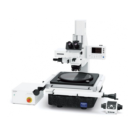
INSTRUCTIONS
STM7
Measuring microscope
This instruction manual is for the Olympus measuring microscope.
To ensure the safety, obtain optimum performance and to familiarize yourself fully with the use
of this microscope, we recommend that you study this manual thoroughly before operating
the microscope.
Retain this instruction manual in an easily accessible place near the work desk for future
reference.
For details of products included in the configuration of this system, see page 13 and 14 of this
Optical Microscope and Accessory
instruction manual.
Advertisement
Table of Contents

Related Manuals for Olympus STM7


Summary of Contents for Olympus STM7
- Page 1 STM7 Measuring microscope This instruction manual is for the Olympus measuring microscope. To ensure the safety, obtain optimum performance and to familiarize yourself fully with the use of this microscope, we recommend that you study this manual thoroughly before operating the microscope.
- Page 2 Refer to your local Olympus distributor in EU for return and/or collection systems available in your country. NOTE: This product has been tested and found to comply with the limits for a Class A digital device, pursuant to Part 15 of the FCC Rules.
-
Page 3: Table Of Contents
Contents Introduction ...............................1 Releasing the transport lock ............................1 Safety precautions ..........................2 1 Nomenclature of module ......................2 Nomenclature of operating portions ................3 Operation procedures ........................ 3-1 Turning Power ON ..............................22 Functioning of Modules ..................................22 X/Y/Z display ......................................23 3-2 Focusing unit (Manual frame only) ......................24 Focusing operation ....................................24 Adjusting the coarse focusing knob tension .........................24 3-3 Hand switch (Manual frame only) .......................25... - Page 4 Erect image monocular observation tube (MM6-EMO) .......................34 3-6 Reflected light illuminator ..........................35 Switching the light path of brightfield/darkfield reflected light illuminator (MM6C-RLAS) ..35 Using the filters (MM6C-KMAS,MM6C-RLAS) .........................35 3-7 Stage ....................................36 Moving the specimen ..................................36 Clamping the option and jig tool ..............................37 Adjusting the parallelism of specimen ..........................37 Replacing the stage glass ................................37 3-8 Focus navigator unit ...............................38...
- Page 5 4-3 Reflected Light Simplified Polarized Light Observation ............48 Observation procedure..................................48 5 MEASUREMENT ..........................5-1 Preparation (setting DIP switch and rotary switch) ..............49 5-2 Measurement of right-angle coordinates ....................54 5-3 Measurement of height (motorized frame only) ................54 5-4 Measurement of cylinders, round rods and screws ..............55 6 ASSEMBLY .............................
-
Page 7: Introduction
This microscope can be combined with the Z-axis motorized type frame or the manual type frame. In this instruction manual, the Z-axis manual type frames (STM7-SF/STM7-MF/STM7-LF) are called "Manual frame" and the Z-axis motorized type frames (STM7-SFA/STM7-MFA/STM7-LFA) are called "Motorized frame". -
Page 8: Safety Precautions
If the STM7 is not installed on a levelled surface, the stage may move spontaneously. Basically, install the STM7 on a table with a thick top board. (Recommended top board thickness: 25 mm or more) Do not put a mat, etc. under the microscope for safety. - Page 9 STM7 CAUTION - Protection for electric shock - Do not insert any tools or metal fragments in the air vents of the device. Doing so could cause electric shock or failure of the product. Do not bend, pull or tie the power cord/cables in a bundle.
- Page 10 Focusing unit the focusing unit opening Focusing unit opening or the stopper. opening Stopper Stopper STM7-SFA/STM7-MFA STM7-LFA When caution labels are dirty or peeled off, contact Olympus for replacement or inquiries.
- Page 11 1. Each module is very heavy. Be sure to carry it by the following number of transport persons. } Number of transport persons per module: 1 or more persons (STM7-CS50, STM7-CS100); 2 or more persons (STM7-SF, STM7-SFA, STM7-MF, STM7-MFA, STM7-CS200); 4 or more persons (STM7-LF, STM7-LFA, STM7-CS300) 2.
- Page 12 } Weight of each unit: 51.8 kg (STM7-SF), 53.8 kg (STM7-SFA), 77.1 kg (STM7-MF), 78.6 kg (STM7-MFA) } Weight applied on one transport stick: Front transport stick Back transport stick of the frame of the frame STM7-SF Approx. 1 kg Approx.
- Page 13 15. The basic software (STM7-BSW) can also be used with the measuring microscope STM6 (with some restrictions). 16. The hardware of STM6 is not compatible with the hardware of STM7. If modules other than modules described in this instruction manual are connected to the microscope, the system may be damaged.
- Page 14 180 mm or more. Stage 100mm 1. The Y-axis knob of the 50x50 mm stage STM7-CS50 or the 100x100 mm stage STM7-CS100 comes out below the stage-mounting surface. When placing the stage on the table, etc., avoid the Y-axis knob 180mm from contacting the table surface.
- Page 15 3. Microsoft Windows has been installed on the controller of this system. Backup and keep the system data in a safe place (Olympus does not provide support for backing up your system data). For more information about the controller and Microsoft Windows , refer to their corresponding manuals.
- Page 16 3. Focusing is possible on specimens with reflectance of glass to mirror. However, it is difficult for the reticle to be able to be seen with the specimens with very irregular surface (surface of a plastic mold, etc.) 4. The brightness of the reticles both top and bottom might be varied. However, there is not a problem in case of use.
- Page 17 5. Relocating the microscope overseas by you without notifying Olympus in advance will not allow you to enjoy the service in the country where the microscope was relocated. 6. If you relocate the microscope overseas, note the following matters: •...
- Page 18 Maintenance and storage 1. Do not leave stains or fingerprints on the lenses. If they get dirty, blow away dust with a commercially available blower and gently wipe the lens or filter with a piece of cleaning paper (or clean gauze).
-
Page 19: Nomenclature Of Module
} The modules shown below are only the basic modules. As there are other modules which can be combined with the microscope but are not shown below, please also refer to the latest Olympus brochures or your dealer. For information on the modules marked with “*", refer to their instruction manuals. - Page 20 · STM7-CS100 (for small motorized frame) · STM7-CS200 (for middle motorized frame) · STM7-CS300 (for large motorized frame) } Either the focus navigator unit STM7-FN or the autofocus unit STM7-AF can be combined with the motorized frame. Option • Foot switch STM7-FS •...
-
Page 21: Nomenclature Of Operating Portions
Interpupillary distance adjustment seats X-RESET button Y-RESET button Z-RESET button Diopter adjustment ring Built into the eyepiece. DATA button Indicator Focusing unit Stage glass Frame · STM7-SF (small manual frame) · STM7-MF (middle manual frame) · STM7-LF (large manual frame) - Page 22 X/Y/Z display Interpupillary distance adjustment seats X-RESET button Y-RESET button Z-RESET button Diopter adjustment ring Built into the eyepiece. DATA button Indicator Stage glass Frame · STM7-SFA (small motorized frame) · STM7-MFA (middle manual frame) · STM7-LFA (large manual frame)
- Page 23 X-axis clutch lever Control box STM7-CB/STM7-CBA } The names of operating portions of the control box for motorized STM7-CBA are illustrated below. The names of the operating portions of the control box for manual STM7-CB are same. Indicator Pilot lamp ON: The main switch is ON.
- Page 24 Focus controller STM7-MCZ * This does not work unless the autofocus unit STM7-AF is connected. Y-RESET button X-RESET button DATA/HALF button AF START/STOP button* SEL button Coarse focusing knob Reflected light illumination/ Transmitted light illumination/ Focus navigator unit Illumination ON/OFF button...
- Page 25 STM7 Brightfield reflected light illuminator MM6C-KMAS Observation tube mount Fiber cable mount Filter insertion slot Analyzer insertion slot Polarizer insertion slot Illuminator mount Revolving nosepiece mount dovetail Brightfield/Darkfield reflected light illuminator MM6C-RLAS Fiber cable mount Observation tube mount Filter insertion slot...
- Page 26 Turn clockwise to increase the light intensity. Main switch : Transmitted light illumination “ ”: ON. “ ”:OFF. Focus navigator unit : Reflected light illumination Focus navigator unit Focus navigator unit STM7-FN LED unit installation block Connector LED light emitter block Green LED unit Cross-frame...
- Page 27 STM7 Autofocus unit STM7-AF Objective magnification indicator LEDs FINE ADJUST knob Used in fine adjustment FOCUS LED of focusing position. Lights when focusing Dummy slider is obtained. Aberration correction seal LASER LED Lights when AF is operated. CBA connector Cross-frame (x 2)
-
Page 28: Operation Procedures
If the emergency stop switch is ON, refer to page 7 and restore it. Set the main switch b on the rear of the control box STM7-CB/STM7- CBA to " " (ON). (Only when using the control box.) Set the main switches of the modules you are using to " " (ON). -
Page 29: X/Y/Z Display
: Transfers the counter data of X-, Y- and Z-axis to Microsoft Office Excel . l Maker setting mode : Sets the microscope. (Ask Olympus to set the microscope.) m Setting : Sets the Excel transfer tool. } For details, refer to Help of Excel transfer tool. -
Page 30: Focusing Unit (Manual Frame Only)
3-2 Focusing unit (Manual frame only) Focusing operation The focusing unit is designed to be lowered (approaching the objective with the specimen) when the coarse focusing knob a or fine focusing knob b is turned in the direction of the arrow. Adjusting the coarse focusing knob tension The tension of the coarse focusing knob is adjustable. -
Page 31: Hand Switch (Manual Frame Only)
(Reflected light illumination/transmitted light illumination/focus navigator unit) } The illumination selected can be confirmed with the indicator g of the control box for manual STM7-CB or the display X h of the digital indicator STM7-DI or the LED k . Reflected light... -
Page 32: Resetting Counter Data Of X-, Y- And Z-Axis
Memorizing light intensity value Keep pressing the SET button d until the buzzer beeps and memorize the current light intensity value of each illumination to the microscope. (Reflected light illumination/transmitted light illumination/ focus navigator unit) } When using the manual revolving nosepiece, the light intensity values of one set (reflected light illumination/transmitted light illumination/focus navigator unit) can be memorized. -
Page 33: Outputting Counter Data Of X-, Y- And Z-Axis
} The ON/OFF of the count-in-half function can be confirmed with the indicator b of the control box for manual STM7-CB or the display X c of the digital indicator STM7-DI or the COUNT d . Count-in-half function: ON Count-in-half function: OFF... -
Page 34: Focus Controller (Motorized Frame Only)
F SENS button d is pressed. The movement distance can be confirmed by the indicator e of the control box for motorized STM7-CBA or the FOCUS f of the digital indicator STM7-DI. Movement distance: Small Movement distance: Large... -
Page 35: Controlling Illumination
(Reflected light illumination/transmitted light illumination/focus navigator unit) } The illumination selected can be confirmed by the indicator b of the control box for motorized STM7-CBA or the display X c of the digital indicator STM7-DI or the LED j . Reflected light... - Page 36 Memorizing light intensity value Keep pressing the SET button h until the buzzer beeps and memorize the current light intensity value of each illumination to the microscope. (Reflected light illumination/transmitted light illumination/ focus navigator unit) } When using the manual revolving nosepiece, the light intensity values of one set (reflected light illumination/transmitted light illumination/focus navigator unit) can be memorized.
-
Page 37: Resetting Counter Data Of X-, Y- And Z-Axis
} The ON/OFF of the count-in-half function can be confirmed by the indicator e of the control box for motorized STM7-CBA or the display X f of the digital indicator STM7-DI or the COUNT g . Count-in-half function: ON Count-in-half function: OFF... -
Page 38: Setting Lower Software Limit
} The status whether the lower software limit is set or cancelled can be confirmed with the Z LIMIT e of the digital indicator STM7-DI. Lower software limit: set Lower software limit: cancelled COUNT... -
Page 39: Observation Tube
STM7-MCZ to bring the specimen on the stage into focus. For details of the focus controller STM7-MCZ, see "3-4 Focus controller (Motorized frame only)" (page 28). Look into the left eyepiece sleeve with the left eye and bring the specimen in focus by rotating only the diopter adjustment ring e on the upper part of the eyepiece. -
Page 40: Replacing The Eyepiece Cross
Replacing the eyepiece cross The cross on each eyepiece sleeve can be replaced except with the MM6-OCC10X. The size other than the cross should be diameter of 24 mm and thickness of 1.5 mm. To attach a new cross, remove the cross-frame b and drop in the cross a so that the side with indications faces downwards. -
Page 41: Reflected Light Illuminator
STM7 3-6 Reflected light illuminator Switching the light path of brightfield/darkfield reflected light illuminator (MM6C-RLAS) Set the brightfield/darkfield switch knob a for the desired observation method. Slide the brightfield/darkfield switch knob correctly into a stopper position. Using the filters (MM6C-KMAS,MM6C-RLAS) Through the filter insertion slot b , insert and engage the filter slider set for the desired observation purpose in the light path. -
Page 42: Stage
. Hold the knob c to move the stage. In case of STM7-CS50, the Y-axis knob is on the left side of the stage. · Do not hold the right side area where a caution label d is CAUTION attached. -
Page 43: Clamping The Option And Jig Tool
Replacing the stage glass When the stage glass is dimmed, scratched or cracked after long hours of use, the stage glass should be replaced. · Ask Olympus to replace the stage glass. CAUTION · The stage glass has been adjusted to ensure flatness. -
Page 44: Focus Navigator Unit
3-8 Focus navigator unit Method of focus Set the main switch a on the rear of the control box STM7-CB/STM7- CBA to " " (ON). (Only when using the control box.) Set the main switches of the modules you are using to " " (ON). -
Page 45: Autofocus Unit (Motorized Frame Only)
Press the AF MODE button d on the focus controller STM7-MCZ. (LASER LED e on the front of the autofocus unit is turned ON and SHOT of the digital indicator STM7-DI blinks to be in the AF standby status.) Press the AF OB button f on the focus controller. - Page 46 Press the AF MODE button d on the focus controller. (The [AF TRACK] indicator c on the front of the control box for motorized is turned ON and TRACK of the digital indicator blinks to be in the TRACK mode.) Press the AF START/STOP button h on the focus controller.
-
Page 47: Measurement By Manual Readout In One Shot Mode
Press the AF MODE button a on the focus controller STM7-MCZ. (LASER LED b on the front of the autofocus unit is turned ON and SHOT of the digital indicator STM7-DI blinks to be in the AF standby status.) Turn ON the objective magnification display LED d on the front of the autofocus unit you want to use by using the AF OB button c of the focus controller. -
Page 48: Measurement By Auto Readout In One Shot Mode
Press the AF MODE button a on the focus controller STM7-MCZ. (LASER LED b on the front of the autofocus unit is turned ON and SHOT of the digital indicator STM7-DI blinks to be in the AF standby status.) Turn ON the objective magnification display LED d on the front of the autofocus unit you want to use by using the AF OB button c of the focus controller. -
Page 49: Measurement In Track Mode
Press the AF MODE button a on the focus controller STM7-MCZ. (LASER LED b on the front of the autofocus unit is turned ON and SHOT of the digital indicator STM7-DI blinks to be in the AF standby status.) Turn ON the objective magnification display LED d on the front of the autofocus unit you want to use by using the AF OB button c of the focus controller. - Page 50 When the unit tracks at the focusing position of a specimen with steep or big level differences, the unit sometimes misses the focusing position and becomes no longer capable of tracking. (FOCUS LED g on the front of the autofocus unit blinks.) Should this be the case, press the AF START/STOP button f on the focusing controller twice to resume the search operation.
-
Page 51: Foot Switch
3-11 Basic software } With the basic software STM7-BSW, various measurements can be performed and measurement results can be saved. For details, refer to the instruction manuals provided with Basic software / MIA,EFI option software. -
Page 52: Observations (Using Mm6C-Kmas Or Mm6C-Rlas)
Otherwise, the U-AN may get stuck in the back and be incapable of being removed. } When using the autofocus unit STM7-AF, insert the analyzer to the analyzer insertion slot d of the autofocus unit. Mount the polarizer U-PO3 b by inserting it into the light path of the reflected light arm MM6C-KMAS or MM6C-RLAS so that the surface with indications faces right. -
Page 53: Setting The Dic Slider
} When using the autofocus unit STM7-AF, the focusing may not be available within the adjustment range (where the interference color is near orange.) of certain DIC prisms. -
Page 54: Reflected Light Simplified Polarized Light Observation
} Place the specimen on the stage, and rotate the fine/coarse focusing knob a of the focusing unit or the fine/coarse focusing knob b of the focus controller STM7-MCZ to bring the specimen on the stage into focus. Now the microscope is ready for simplified polarized light observation. -
Page 55: Measurement
STM7 MEASUREMENT 5-1 Preparation (setting DIP switch and rotary switch) } Following settings are available by the DIP switch of the control box STM7-CB/STM7-CBA. 1) Unit (μm/mm/inch/mil) 2) Minimum digit 3) Buzzer 4) Restoration of light intensity value at startup... - Page 56 Restoration of light intensity value and objective magnification at startup Set whether or not to load the last light intensity value memorized to the microscope with the hand switch STM7-HS or the focus controller STM7-MCZ when you start the microscope.
- Page 57 Output of counter data when LASER LED of the autofocus unit is turned ON When using the autofocus unit STM7-AF and the LASER LED is turned ON, set functions when the DATA/HALF button of the focus controller STM7-MCZ is pressed.
- Page 58 Time to display the information of the microscope When operating each button of the hand switch STM7-HS or the focus controller STM7-MCZ, set the display time of the current microscope setting information on the digital indicator STM7-DI. Setting items DIP switch...
- Page 59 Bring the specimen in focus by moving the reflected light arm up and down with the coarse focusing knob on the focusing unit of the microscope or the FOCUS buttons on the focus controller STM7-MCZ. Adjust focusing more precisely using the fine focusing knob on the focusing unit of the microscope or using the fine/coarse focusing knob on the focus controller.
-
Page 60: Measurement Of Right-Angle Coordinates
5-2 Measurement of right-angle coordinates } The operability can be improved by using the rotatable stage STM7- RS100/STM7-RS200/STM7-RS300. Place the specimen on the center of the stage glass. Determine the origin, X-axis and Y-axis of the specimen, and align the direction of stage travel with the axes. -
Page 61: Measurement Of Cylinders, Round Rods And Screws
STM7 5-4 Measurement of cylinders, round rods and screws To measure a cylinder, round rod or screw, place the item to be measured directly on the stage glass or use an optional V-shaped support. Measuring a Cylinder or Round Rod For measurement, align the axis of the measured item with either direction of the table travel (normally, X-axis). -
Page 62: Assembly
The numbers indicate the order of assembly. The modules shown in the following diagram are merely the basic ones. For the modules which are not shown in the diagram, please consult your Olympus representative or the latest brochures. · The assembly and adjustments are performed by the Olympus dealer. As other tools than those provided CAUTION with instrument are necessary, the dealer should prepare them. -
Page 63: Detailed Assembly Procedures
STM7 6-2 Detailed assembly procedures · Before assembling the microscope, set the main switch of the control box STM7-CB/STM7-CBA to " " (OFF) CAUTION and unplug the power cord. · The frame and the stage are very heavy. Pay a careful attention when carrying them. For the number of transport persons, refer to page 5. - Page 64 Fit the screw holes a (2 pcs.) on the right of the column with the screw holes b of the digital indicator STM7-DI, and secure the clamping screws b (2 pcs.) provided with the digital indicator by using the Allen screwdriver provided with the frame.
- Page 65 } When using the motorized frame, refer to "15 Connecting cable and cords" (page 69) and connect cables and cords. Then, set the main switch b of the control box for motorized STM7-CBA to " "(ON) and rotate the coarse focusing knob c of the focusing controller STM7- MCZ to raise the focusing unit as much as possible.
- Page 66 In case of STM7-CS200 or STM7-CS300, take out the inner box f from the packaging box. Take out the protecting sheet g from the packaging box. In case of STM7-CS200 or STM7-CS300, take out the stage by holding the transport sticks h (4 positions).
- Page 67 Allen wrench provided with the frame, and remove the locks. } In case of STM7-CS50 or STM7-CS100, the stage transport locks are attached to the lower front area and the right side of the stage. } In case of STM7-CS200 or STM7-CS300, the stage transport locks are attached to the rear side and the right side of the stage.
- Page 68 Leveling the stage Place the level provided by the sales office on the stage glass g . Adjust the legs h (2 each on front and back) of the frame to level front/back/right/left by using the spanner. When the X-axis or Y-axis clutch is released with the stage position as a center position, make sure that the stage does not move spontaneously in either X or Y direction.
- Page 69 STM7 Mounting the reflected light illuminator (MM6C-KMAS, MM6C-RLAS) Fully loosen the clamp f (stud) of the reflected light arm e using the Allen screwdriver provided with the frame. Fit the reflected light arm e into the mount dovetail on the frame all the way until it is stopped.
- Page 70 Mounting the objective (MM6C-VL) } When using the reflected light arm MM6C-VL, only one objective can be attached because the reflected light arm does not use a revolving nosepiece. MM6-OB series objective Mount the desired MM6-OB series objective k into the objective mount j by screwing in firmly.
- Page 71 Allen screwdriver provided with the frame. Insert the dovetails of the adapter to mount measuring objectives STM7-MMOBAD h into the objective attaching area of the reflected light illuminator arm from the front. And push it until it touches the end.
- Page 72 Fully loosen the tube clamping screw g using the Allen screwdriver provided with the microscope frame. } When using the autofocus unit STM7-AF, fully loosen the tube clamping screw of the autofocus unit using the Allen screwdriver provided with the microscope frame.
- Page 73 STM7 Mounting the eyepiece · The MM6-OCC10X eyepiece with cross hairs should always CAUTION be attached to the right microscope sleeve (in case of a binocular tube). · Use the MM6-OCC10X eyepiece for the erect image monocular observation tube MM6-EMO.
- Page 74 Insert the white LED unit (MM6-ILW) a into the port on the reflected light unit and clamp with the clamping knob b . Insert the green LED unit (MM6-ILG) into the frame. STM7-SF/STM7-SFA/STM7-MF/STM7-MFA STM7-SF/STM7-SFA/STM7-MF/STM7-MFA Insert the green LED unit (MM6-ILG) c into the lower part on the rear of the frame, and clamp with the clamping knob d .
- Page 75 STM7-FS (motorized frame only) Power cord 70 mm To HS of control box (manual frame only) Connector of STM7-MCZ Focus controller } Attach the ferrite core a provided with STM7-MCZ to the interface Hand switch STM7-MCZ STM7-HS cable (optional accessory).
- Page 76 } For connections of positions with * Control box STM7-CB/STM7-CBA mark, contact Olympus for details. Power cord Coded quintuple revolving nosepiece · When connecting DISPLAY of the control box with the digital indicator, check the pin positions of the CAUTION connector of the cable for digital indicator.
- Page 77 Allen screwdriver provided with the microscope frame. (In case of STM7-CS50 or STM7-CS100, the connection destination of the functional ground cable is at the rear of the stage.)
- Page 78 Front view of microscope (when combined with STM7-CU) } Explanations other than the camera connector position are same as the case when combined with DP22/DP27.
- Page 79 } When all assemblies are completed, make sure the counting status of X-, Y - and Z-axis, unit of the counter display, operations of X- and Y-axis knobs, Z-axis driving, operations of the hand switch STM7-HS or the focus controller STM7-MCZ, etc.
-
Page 80: Inputting Setting Values (Maker Setting Mode)
} When the microscope is assembled, input the setting values. If the setting values are not inputted, an error sound beeps (three short beeps) when the main switch of the control box STM7-CB/STM7-CBA is set to " "(ON). (If you are using the control box for motorized STM7-CBA and also the origin search setting is ON, the error sound beeps when the origin search is finished.) - Page 81 STM7 While pressing the X-, Y- and Z-RESET buttons a of the digital indicator at the same time, set the main switch b of the control box STM7-CB/ STM7-CBA to " " (ON). Keep pressing the X-, Y- and Z-RESET buttons, and wait for approx. 3 seconds.
- Page 82 Inputting the measured value of X-axis Press the X-RESET button c to show ”3” in the display X. Press the DATA button f to change the digit you want to edit in the display Y. Press the Y-RESET button d or the Z-RESET button e to set the COUNT FOCUS Z LIMIT...
- Page 83 STM7 Setting the Z-axis counting direction Press the X-RESET button c to show ”7” in the display X. Press the Y-RESET button d or the Z-RESET button e to set the Z-axis counting direction in the display Y. } For setting values, see "2 Setting Function List" (page 79).
- Page 84 Closing the maker setting mode Press the X-RESET button c to show ”12” in the display X. Press the Y-RESET button d or the Z-RESET button e to show "1" in the display Y. Press the DATA button f . COUNT FOCUS Z LIMIT...
- Page 85 STM7 Maker setting mode Setting values in the maker setting mode must be inputted by Olympus. Do not change the setting values by yourselves. The work to solve the problems caused by changing the setting values are for compensation. Setting Function List...
-
Page 86: Mounting And Operating A Video System
For details, refer to the instructions of the video system to be used. } Use the trinocular observation tube (MM6-ETR) in combination with a video system. } For the digital camera STM7-CU, attach the camera adapter to the microscope so that the connector comes to the right side. -
Page 87: Adjusting The Tilt Of The Camera
STM7 7-1 Adjusting the tilt of the camera When the microscope digital camera is attached to the camera adapter, the tilt must be adjusted. } For adjustment, use the measurement objects (metal scales or screwdriver, etc.) which can cover the stage movable range (X -axis) in line. - Page 88 Move the X-axis to right and left ends. Repeat from until the edge of the measurement object always comes to the center of the cross line. Rotate the eyepiece sleeve along the edge of the objective. Tighten the clamping knob with the tool provided with the frame to fix the eyepiece with cross hairs.
-
Page 89: Specifications
*2 The height of the specimen which can be placed at the position more than ±180 mm farther from the center of measurement (light axis) in the X- or Y-axis direction is 100 mm or less. *3 If you want to load those other than the standard combinations, contact Olympus. - Page 90 Stage Specifications Item STM7-CS50 STM7-CS100 STM7-CS200 STM7-CS300 Stage top size Ø140 mm 210x210 mm 360x360 mm 510x510 mm Stage glass size Ø100 mm 144x144 mm 249x249 mm 349x349 mm Measuring range X50mm, Y50 mm X100 mm, Y100 mm X200 mm, Y200 mm...
- Page 91 · Measurement objectives · Measurement objectives in combination with adapter (used in combination with (used in combination with BD-M-AD) adapter to mount measuring adapter to mount measuring objectives STM7-MMOBAD) objectives STM7-MMOBAD) Dimensions 119(W)x148(D)x95(H) mm 241(W)x148(D)x128.5(H) mm 261(W)x158(D)x128.5(H) mm Weight Approx. 2.6 kg Approx.
- Page 92 SHOT ON: The autofocusing is being operated in ONE SHOT mode. FOCUS COARSE ON: The movement distance of the fine/coarse focusing knob of the focus controller STM7- MCZ is large. FINE ON: The movement distance of the fine/coarse focusing knob of the focus controller STM7- MCZ is small.
- Page 93 Reset counter data of X-, Y - and Z-axis Output counter data of X-, Y - and Z-axis Lower software limit setting Autofocus unit STM7-AF control Memorize/load light intensity value and objective magnification Sensitivity of fine/coarse focusing knob Counting of counter data in-half...
- Page 94 Average life Approx. 30000 hours (Ambient temperature 20°C, light intensity level 50%) Control box STM7-CB/STM7-CBA Refer to the instruction manual provided with the control box STM7-CB/STM7-CBA. Autofocus unit STM7-AF Refer to the instruction manual provided with the autofocus unit STM7-AF.
- Page 95 STM7 Power supply unit MM6-ILPS-2 Refer to the instruction manual provided with the power supply unit MM6-ILPS-2. Operating environment Ambient temperature/ Accuracy guarantee Temperature: 20 °C±1 °C Humidity: 65%±20% humidity Operation guarantee Temperature: 10 °C to 35 °C Humidity: 30% to 85% Standby condition Temperature: 0 °C to 40 °C...
-
Page 96: Troubleshooting Guide
Under certain conditions, performance of the microscope may be adversely affected by factors other than defects. If problems occur, please review the following list and take remedial action as needed. If you cannot solve the problem after checking the entire list, please contact Olympus for assistance. Problem... - Page 97 (clockwise), and then rotate the fine/coarse focusing knob of the focus controller STM7-MCZ to move the focusing unit to the safe position. Then, set the main switch of the control box for motorized to " " (OFF), and set the main switch of the control box for motorized to "...
- Page 98 Display shows "013F0500". The setting value is not inputted. Input the setting value. g) Display shows "013F1503". The hand switch STM7-HS is not Connect the cable. connected to the control box for manual STM7-CB. h) Display shows "013F1504".
- Page 99 Perform the measurement again. If you cannot solve the problem, contact Olympus for assistance. m) Display shows "013F1521". The Y scale cable is disconnected or the Connect the Y-scale cable properly abnormality is detected in the scale.
-
Page 100: Proper Selection Of The Power Supply Cord
If no power supply cord is provided, please select the proper power supply cord for the equipment by referring to “Specifications” and “Certified Cord” below: Caution : In case you use a non-approved power supply cord for Olympus products, Olympus can no longer warrant the electrical safety of the equipment. - Page 101 STM7 Table 2 HAR flexible cord Approval organizations and cordage harmonization marking methods Alternative marking utilizing Printed or embossed black-red-yellow thread (Length harmonization marking (May be of color section in mm) Approval organization located on jacket or insulation of internal wiring)
- Page 102 Memo...
- Page 104 Manufactured by Shinjuku Monolith, 2-3-1 Nishi-Shinjuku, Shinjuku-ku, Tokyo 163-0914, Japan Distributed by AX8428 11 Issued in January, 2020...
Need help?
Do you have a question about the STM7 and is the answer not in the manual?
Questions and answers